About External Layer-3 Connectivity for VXLAN BGP EVPN Fabrics
A VXLAN BGP EVPN fabric can be extended by using per-VRF IP routing to achieve external connectivity. The approach that is used for the Layer-3 extensions is commonly referred to as VRF Lite, while the functionality itself is more accurately defined as Inter-AS Option A or back-to-back VRF connectivity.
VXLAN BGP EVPN - VRF-lite brief
Some pointers are given below:
-
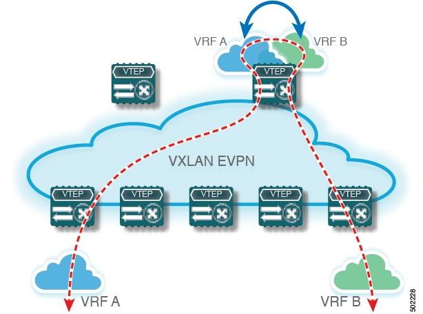
The VXLAN BGP EVPN fabrics is depicted on the left in the following figure.
-
Routes within the fabric are exchanged between all Edge-Devices (VTEPs) as well as Route-Reflectors; the control-plane used is MP-BGP with EVPN address-family.
-
The Edge-Devices (VTEPs) acting as border nodes are configured to pass on prefixes to the external router (ER). This is achieved by exporting prefixes from MP-BGP EVPN to IPv4/IPv6 per-VRF peerings.
-
Various routing protocols can be used for the per-VRF peering. While eBGP is the protocol of choice, IGPs like OSPF, IS-IS or EIGRP can be leveraged but require redistribution

Guidelines and Limitations for External VRF Connectivity and Route Leaking
The following guidelines and limitations apply to external Layer 3 connectivity for VXLAN BGP EVPN fabrics:
-
Support is added for Cisco Nexus 9504 and 9508 platform switches with Cisco Nexus 96136YC-R and 9636C-RX line cards.
-
A physical Layer 3 interface (parent interface) can be used for external Layer 3 connectivity (that is, VRF default).
-
The parent interface to multiple subinterfaces cannot be used for external Layer 3 connectivity (that is, Ethernet1/1 for a VRF default). You can use a subinterface instead.
-
Beginning with Cisco NX-OS Release 9.3(5), VTEPs support VXLAN-encapsulated traffic over parent interfaces if subinterfaces are configured.
-
VTEPs do not support VXLAN-encapsulated traffic over subinterfaces, regardless of VRF participation or IEEE 802.1Q encapsulation.
-
Mixing subinterfaces for VXLAN and non-VXLAN VLANs is not supported.
-
The import map command applied under address-family ipv4 unicast does not control what gets imported into the EVPN table L3VNI counterpart.
-
If TRM is configured, SVIs must not be used to interconnect to the external router.
Configuring VXLAN BGP EVPN with eBGP for VRF-lite
Configuring VRF for VXLAN Routing and External Connectivity using BGP
Configure the VRF on the border node.
SUMMARY STEPS
- configure terminal
- vrf context vrf-name
- vni number
- rd {auto | rd}
- address-family {ipv4 | ipv6} unicast
- route-target both {auto | rt}
- route-target both {auto | rt} evpn
- Repeat Step 1 through Step 7 for every L3VNI.
DETAILED STEPS
| Command or Action | Purpose | |
|---|---|---|
|
Step 1 |
configure terminal |
Enter global configuration mode. |
|
Step 2 |
vrf context vrf-name |
Configure the VRF. |
|
Step 3 |
vni number |
Specify the VNI. The VNI associated with the VRF is often referred to as a Layer 3 VNI, L3VNI, or L3VPN. The L3VNI is configured as the common identifier across the participating VTEPs. |
|
Step 4 |
rd {auto | rd} |
Specify the VRF's route distinguisher (RD). The RD uniquely identifies a VTEP within an L3VNI. If you enter an RD, the following formats are supported: ASN2:NN, ASN4:NN, or IPV4:NN. |
|
Step 5 |
address-family {ipv4 | ipv6} unicast |
Configure the IPv4 or IPv6 unicast address family. |
|
Step 6 |
route-target both {auto | rt} |
Configure the route target (RT) for import and export of IPv4 prefixes. The RT is used for a per-VRF prefix import/export policy. If you enter an RT, the following formats are supported: ASN2:NN, ASN4:NN, or IPV4:NN. Manually configured RTs are required to support asymmetric VNIs. |
|
Step 7 |
route-target both {auto | rt} evpn |
Configure the route target (RT) for import and export of IPv4 prefixes. The RT is used for a per-VRF prefix import/export policy. If you enter an RT, the following formats are supported: ASN2:NN, ASN4:NN, or IPV4:NN. Manually configured RTs are required to support asymmetric VNIs. |
|
Step 8 |
Repeat Step 1 through Step 7 for every L3VNI. |
Configuring the L3VNI's Fabric Facing VLAN and SVI on the Border Node
SUMMARY STEPS
- configure terminal
- vlan number
- vn-segment number
- interface vlan-number
- mtu value
- vrf member vrf-name
- ip forward
- no ip redirects
- ipv6 ip-address
- no ipv6 redirects
- Repeat Step 2 through Step 10 for every L3VNI.
DETAILED STEPS
| Command or Action | Purpose | |
|---|---|---|
|
Step 1 |
configure terminal |
Enter configuration mode. |
|
Step 2 |
vlan number |
Specify the VLAN id that is used for the L3VNI. |
|
Step 3 |
vn-segment number |
Map the L3VNI to the VLAN for VXLAN EVPN routing. |
|
Step 4 |
interface vlan-number |
Specify the SVI (Switch Virtual Interface) for VXLAN EVPN routing. |
|
Step 5 |
mtu value |
Specify the MTU for the L3VNI. |
|
Step 6 |
vrf member vrf-name |
Map the SVI to the matching VRF context. |
|
Step 7 |
ip forward |
Enable IPv4 forwarding for the L3VNI. |
|
Step 8 |
no ip redirects |
Disable ICMP redirects |
|
Step 9 |
ipv6 ip-address |
Enable IPv6 forwarding for the L3VNI. |
|
Step 10 |
no ipv6 redirects |
Disable ICMPv6 redirects. |
|
Step 11 |
Repeat Step 2 through Step 10 for every L3VNI. |
Configuring the VTEP on the Border Node
SUMMARY STEPS
- configure terminal
- interface nve1
- member vni vni associate-vrf
DETAILED STEPS
| Command or Action | Purpose | |
|---|---|---|
|
Step 1 |
configure terminal |
Enter global configuration mode. |
|
Step 2 |
interface nve1 |
Configure the NVE interface. |
|
Step 3 |
member vni vni associate-vrf |
Add Layer-3 VNIs, one per tenant VRF, to the overlay. |
|
Step 4 |
|
Repeat Step 3 for every L3VNI. |
Configuring the BGP VRF Instance on the Border Node for IPv4 per-VRF Peering
SUMMARY STEPS
- configure terminal
- router bgp autonomous-system-number
- vrf vrf-name
- address-family ipv4 unicast
- advertise l2vpn evpn
- maximum-paths ibgp number
- maximum-paths number
- neighbor address remote-as number
- update-source type/id
- address-family ipv4 unicast
- Repeat Step 3 through Step 10 for every L3VNI that requires external connectivity for IPv4.
DETAILED STEPS
| Command or Action | Purpose | |
|---|---|---|
|
Step 1 |
configure terminal |
Enter global configuration mode. |
|
Step 2 |
router bgp autonomous-system-number |
Configure BGP. The range of the autonomous-system-number is from 1 to 4294967295. |
|
Step 3 |
vrf vrf-name |
Specify the VRF. |
|
Step 4 |
address-family ipv4 unicast |
Configure address family for IPv4. |
|
Step 5 |
advertise l2vpn evpn |
Enable the advertisement of EVPN routes within IPv4 address-family. |
|
Step 6 |
maximum-paths ibgp number |
Enabling equal cost multipathing (ECMP) for iBGP prefixes. The range for number if 1 to 64. The default is 1. |
|
Step 7 |
maximum-paths number |
Enabling equal cost multipathing (ECMP) for eBGP prefixes. |
|
Step 8 |
neighbor address remote-as number |
Define eBGP neighbor IPv4 address and remote Autonomous-System (AS) number. |
|
Step 9 |
update-source type/id |
Define interface for eBGP peering. |
|
Step 10 |
address-family ipv4 unicast |
Activate the IPv4 address family for IPv4 prefix exchange. |
|
Step 11 |
Repeat Step 3 through Step 10 for every L3VNI that requires external connectivity for IPv4. |
Configuring the BGP VRF Instance on the Border Node for IPv6 per-VRF Peering
SUMMARY STEPS
- configure terminal
- router bgp autonomous-system-number
- vrf vrf-name
- address-family ipv6 unicast
- advertise l2vpn evpn
- maximum-paths ibgp number
- maximum-paths number
- neighbor address remote-as number
- update-source type/id
- address-family ipv6 unicast
- Repeat Step 3 Through Step 10 for every L3VNI that requires external connectivity for IPv6.
DETAILED STEPS
| Command or Action | Purpose | |
|---|---|---|
|
Step 1 |
configure terminal |
Enter global configuration mode. |
|
Step 2 |
router bgp autonomous-system-number |
Configure BGP. |
|
Step 3 |
vrf vrf-name |
Specify the VRF. |
|
Step 4 |
address-family ipv6 unicast |
Configure address family for IPv4. |
|
Step 5 |
advertise l2vpn evpn |
Enable the advertisement of EVPN routes within IPv6 address-family. |
|
Step 6 |
maximum-paths ibgp number |
Enabling equal cost multipathing (ECMP) for iBGP prefixes. |
|
Step 7 |
maximum-paths number |
Enabling equal cost multipathing (ECMP) for eBGP prefixes. |
|
Step 8 |
neighbor address remote-as number |
Define eBGP neighbor IPv6 address and remote Autonomous-System (AS) number. |
|
Step 9 |
update-source type/id |
Define interface for eBGP peering. |
|
Step 10 |
address-family ipv6 unicast |
Configure address family for IPv6. |
|
Step 11 |
Repeat Step 3 Through Step 10 for every L3VNI that requires external connectivity for IPv6. |
Configuring the Sub-Interface Instance on the Border Node for Per-VRF Peering - Version 1
SUMMARY STEPS
- configure terminal
- interface type/id
- no switchport
- no shutdown
- exit
- interface type/id
- encapsulation dot1q number
- vrf member vrf-name
- ip address address
- no shutdown
- Repeat Step 5 through Step 9 for every per-VRF peering.
DETAILED STEPS
| Command or Action | Purpose | |
|---|---|---|
|
Step 1 |
configure terminal |
Enters global configuration mode. |
|
Step 2 |
interface type/id |
Configure parent interface. |
|
Step 3 |
no switchport |
Disable Layer-2 switching mode on interface. |
|
Step 4 |
no shutdown |
Bring up parent interface. |
|
Step 5 |
exit |
Exit interface configuration mode. |
|
Step 6 |
interface type/id |
Define the Sub-Interface instance. |
|
Step 7 |
encapsulation dot1q number |
Configure the VLAN ID for the sub-interface. The number argument can have a value from 1 to 3967. |
|
Step 8 |
vrf member vrf-name |
Map the Sub-Interface to the matching VRF context. |
|
Step 9 |
ip address address |
Configure the Sub-Interfaces IP address. |
|
Step 10 |
no shutdown |
Bring up Sub-Interface. |
|
Step 11 |
Repeat Step 5 through Step 9 for every per-VRF peering. |
VXLAN BGP EVPN - Default-Route, Route Filtering on External Connectivity
About Configuring Default Routing for External Connectivity
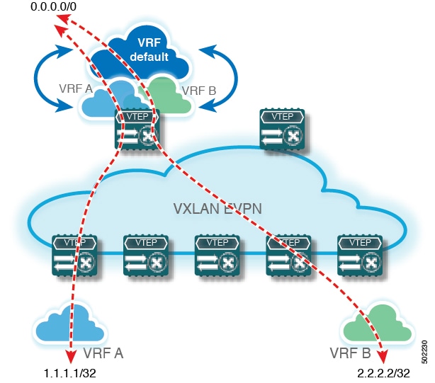
For default-route advertisement into a VXLAN BGP EVPN fabric, we have to ensure that the default-route advertised into the fabric is at the same time not advertised outside of the fabric. For this case, it is necessary to have route filtering in place that prevents this eventuality.
Configuring the Default Route in the Border Nodes VRF
SUMMARY STEPS
- configure terminal
- vrf context vrf-name
- ip route 0.0.0.0/0 next-hop
- ipv6 route 0::/0 next-hop
DETAILED STEPS
| Command or Action | Purpose | |
|---|---|---|
|
Step 1 |
configure terminal |
Enters global configuration mode. |
|
Step 2 |
vrf context vrf-name |
Configure the VRF. |
|
Step 3 |
ip route 0.0.0.0/0 next-hop |
Configure the IPv4 default-route. |
|
Step 4 |
ipv6 route 0::/0 next-hop |
Configure the IPv6 default-route. |
Configuring the BGP VRF Instance on the Border Node for IPv4/IPv6 Default-Route Advertisement
SUMMARY STEPS
- configure terminal
- router bgp autonomous-system-number
- vrf vrf-name
- address-family ipv4 unicast
- network 0.0.0.0/0
- address-family ipv6 unicast
- network 0::/0
- neighbor addressremote-as number
- update-source type/id
- address-family {ipv4 | ipv6} unicast
- route-map name out
- Repeat Step 3 through Step 11 for every L3VNI that requires external connectivity with default-route filtering.
DETAILED STEPS
| Command or Action | Purpose | |
|---|---|---|
|
Step 1 |
configure terminal |
Enters global configuration mode. |
|
Step 2 |
router bgp autonomous-system-number |
Configure BGP. |
|
Step 3 |
vrf vrf-name |
Specify the VRF. |
|
Step 4 |
address-family ipv4 unicast |
Configure the IPv4 Unicast address-family. Required for IPv6 over VXLAN with IPv4 underlay. |
|
Step 5 |
network 0.0.0.0/0 |
Creating IPv4 default-route network statement. |
|
Step 6 |
address-family ipv6 unicast |
Configure the IPv6 unicast address-family. |
|
Step 7 |
network 0::/0 |
Creating IPv6 default-route network statement. |
|
Step 8 |
neighbor addressremote-as number |
Define eBGP neighbor IPv4 address and remote Autonomous-System (AS) number. |
|
Step 9 |
update-source type/id |
Define interface for eBGP peering |
|
Step 10 |
address-family {ipv4 | ipv6} unicast |
Activate the IPv4 or IPv6 address family for IPv4/IPv6 prefix exchange. |
|
Step 11 |
route-map name out |
Attach route-map for egress route filtering. |
|
Step 12 |
Repeat Step 3 through Step 11 for every L3VNI that requires external connectivity with default-route filtering. |
Configuring Route Filtering for IPv4 Default-Route Advertisement
You can configure route filtering for IPv4 default-route advertisement.
SUMMARY STEPS
- configure terminal
- ip prefix-list name seq 5 permit 0.0.0.0/0
- route-map name deny 10
- match ip address prefix-list name
- route-map name permit 1000
DETAILED STEPS
| Command or Action | Purpose | |
|---|---|---|
|
Step 1 |
configure terminal |
Enters global configuration mode. |
|
Step 2 |
ip prefix-list name seq 5 permit 0.0.0.0/0 |
Configure IPv4 prefix-list for default-route filtering. |
|
Step 3 |
route-map name deny 10 |
Create route-map with leading deny statement to prevent the default-route of being advertised via External Connectivity. |
|
Step 4 |
match ip address prefix-list name |
Match against the IPv4 prefix-list that contains the default-route. |
|
Step 5 |
route-map name permit 1000 |
Create route-map with trailing allow statement to advertise non-matching routes via External Connectivity. |
Configuring Route Filtering for IPv6 Default-Route Advertisement
SUMMARY STEPS
- configure terminal
- ipv6 prefix-list name seq 5 permit 0::/0
- route-map name deny 10
- match ipv6 address prefix-list name
- route-map name permit 1000
DETAILED STEPS
| Command or Action | Purpose | |
|---|---|---|
|
Step 1 |
configure terminal |
Enters global configuration mode. |
|
Step 2 |
ipv6 prefix-list name seq 5 permit 0::/0 |
Configure IPv6 prefix-list for default-route filtering. |
|
Step 3 |
route-map name deny 10 |
Create route-map with leading deny statement to prevent the default-route of being advertised via External Connectivity. |
|
Step 4 |
match ipv6 address prefix-list name |
Match against the IPv6 prefix-list that contains the default-route. |
|
Step 5 |
route-map name permit 1000 |
Create route-map with trailing allow statement to advertise non-matching routes via External Connectivity. |
About Configuring Default-Route Distribution and Host-Rote Filter
Per-default, a VXLAN BGP EVPN fabric always advertises all known routes via the External Connectivity. As not in all circumstances it is beneficial to advertise IPv4 /32 or IPv6 /128 Host-Routes, a respective route filtering approach can become necessary.
Configuring the BGP VRF Instance on the Border Node for IPv4/IPv6 Host-Route Filtering
SUMMARY STEPS
- configure terminal
- router bgp autonomous-system-number
- vrf vrf-name
- neighbor address remote-as number
- update-source type/id
- address-family {ipv4 | ipv6} unicast
- route-map name out
- Repeat Step 3 through Step 7 for every L3VNI that requires external connectivity with host-route filtering.
DETAILED STEPS
| Command or Action | Purpose | |
|---|---|---|
|
Step 1 |
configure terminal |
Enters global configuration mode. |
|
Step 2 |
router bgp autonomous-system-number |
Configure BGP. |
|
Step 3 |
vrf vrf-name |
Specify the VRF. |
|
Step 4 |
neighbor address remote-as number |
Define eBGP neighbor IPv4/IPv6 address and remote Autonomous-System (AS) number. |
|
Step 5 |
update-source type/id |
Define interface for eBGP peering. |
|
Step 6 |
address-family {ipv4 | ipv6} unicast |
Activate the IPv4 or IPv6 address family for IPv4/IPv6 prefix exchange. |
|
Step 7 |
route-map name out |
Attach route-map for egress route filtering. |
|
Step 8 |
Repeat Step 3 through Step 7 for every L3VNI that requires external connectivity with host-route filtering. |
|
Configuring Route Filtering for IPv4 Host-Route Advertisement
SUMMARY STEPS
- configure terminal
- ip prefix-list name seq 5 permit 0.0.0.0/0 eq 32
- route-map name deny 10
- match ip address prefix-list name
- route-map name permit 1000
DETAILED STEPS
| Command or Action | Purpose | |
|---|---|---|
|
Step 1 |
configure terminal |
Enters global configuration mode. |
|
Step 2 |
ip prefix-list name seq 5 permit 0.0.0.0/0 eq 32 |
Configure IPv4 prefix-list for host-route filtering. |
|
Step 3 |
route-map name deny 10 |
Create route-map with leading deny statement to prevent the default-route of being advertised via External Connectivity. |
|
Step 4 |
match ip address prefix-list name |
Match against the IPv4 prefix-list that contains the host-route. |
|
Step 5 |
route-map name permit 1000 |
Create route-map with trailing allow statement to advertise non-matching routes via external connectivity. |
Configuring Route Filtering for IPv6 Host-Route Advertisement
SUMMARY STEPS
- configure terminal
- ipv6 prefix-list name seq 5 permit 0::/0 eq 128
- route-map name deny 10
- match ipv6 address prefix-list name
- route-map name permit 1000
DETAILED STEPS
| Command or Action | Purpose | |
|---|---|---|
|
Step 1 |
configure terminal |
Enters global configuration mode. |
|
Step 2 |
ipv6 prefix-list name seq 5 permit 0::/0 eq 128 |
Configure IPv4 prefix-list for host-route filtering. |
|
Step 3 |
route-map name deny 10 |
Create route-map with leading deny statement to prevent the default-route of being advertised via External Connectivity. |
|
Step 4 |
match ipv6 address prefix-list name |
Match against the IPv4 prefix-list that contains the host-route. |
|
Step 5 |
route-map name permit 1000 |
Create route-map with trailing allow statement to advertise non-matching routes via External Connectivity. |
Example - Configuring VXLAN BGP EVPN with eBGP for VRF-lite
Configuring VXLAN BGP EVPN Border Node
An example of external connectivity from VXLAN BGP EVPN to an external router using VRF-lite.
The VXLAN BGP EVPN Border Node acts as neighbor device to the External Router. The VRF Name is purely localized and can be different to the VRF Name on the External Router, only significance is the L3VNI must be consistent across the VXLAN BGP EVPN fabric. For the ease of reading, the VRF and interface enumeration will be consistently used.
The configuration examples represents a IPv4 and IPv6 dual-stack approach; IPv4 or IPv6 can be substituted of each other.
vrf context myvrf_50001
  vni 50001
  rd auto
  address-family ipv4 unicast
    route-target both auto
    route-target both auto evpn
  address-family ipv6 unicast
    route-target both auto
    route-target both auto evpn
!
vlan 2000
  vn-segment 50001
!
interface Vlan2000
  no shutdown
  mtu 9216
  vrf member myvrf_50001
  no ip redirects
  ip forward
  ipv6 address use-link-local-only
  no ipv6 redirects
!
interface nve1
  no shutdown
  host-reachability protocol bgp
  source-interface loopback1
  member vni 50001 associate-vrf
!
router bgp 65002
  vrf myvrf_50001
    router-id 10.2.0.6
    address-family ipv4 unicast
      advertise l2vpn evpn
      maximum-paths ibgp 2
      maximum-paths 2
    address-family ipv6 unicast
      advertise l2vpn evpn
      maximum-paths ibgp 2
      maximum-paths 2
    neighbor 10.31.95.95
      remote-as 65099
      address-family ipv4 unicast
    neighbor 2001::95/64
      remote-as 65099
      address-family ipv4 unicast
!
interface Ethernet1/3
  no switchport
  no shutdown
interface Ethernet1/3.2
  encapsulation dot1q 2
  vrf member myvrf_50001
  ip address 10.31.95.31/24
  ipv6 address 2001::31/64
  no shutdown
Configuring Default-Route, Route Filtering on External Connectivity
The VXLAN BGP EVPN Border Node has the ability to advertise IPv4 and IPv6 default-route within the fabric. In cases where it is not beneficial to advertise the Host Routes from the VXLAN BGP EVPN fabric to the External Router, these IPv4 /32 and IPv6 /128 can be filtered at the External Connectivity peering configuration.
ip prefix-list default-route seq 5 permit 0.0.0.0/0 le 1
ipv6 prefix-list default-route-v6 seq 5 permit 0::/0
!
ip prefix-list host-route seq 5 permit 0.0.0.0/0 eq 32
ipv6 prefix-list host-route-v6 seq 5 permit 0::/0 eq 128
!
route-map extcon-rmap-filter deny 10
  match ip address prefix-list default-route
route-map extcon-rmap-filter deny 20
  match ip address prefix-list host-route
route-map extcon-rmap-filter permit 1000
!
route-map extcon-rmap-filter-v6 deny 10
  match ipv6 address prefix-list default-route-v6
route-map extcon-rmap-filter-v6 deny 20
  match ip address prefix-list host-route-v6
route-map extcon-rmap-filter-v6 permit 1000
!
vrf context myvrf_50001
  ip route 0.0.0.0/0 10.31.95.95
  ipv6 route 0::/0 2001::95/64
!
router bgp 65002
  vrf myvrf_50001
    address-family ipv4 unicast
      network 0.0.0.0/0
    address-family ipv6 unicast
      network 0::/0


    neighbor 10.31.95.95
      remote-as 65099
      address-family ipv4 unicast
        route-map extcon-rmap-filter out
    neighbor 2001::95/64
      remote-as 65099
      address-family ipv4 unicast
        route-map extcon-rmap-filter-v6 out
Configuring External Router
The External Router performs as a neighbor device to the VXLAN BGP EVPN border node. The VRF Name is purely localized and can be different to the VRF Name on the VXLAN BGP EVPN Fabric. For the ease of reading, the VRF and interface enumeration will be consistently used.
The configuration examples represents a IPv4 and IPv6 dual-stack approach; IPv4 or IPv6 can be substituted of each other.
vrf context myvrf_50001
!
router bgp 65099
  vrf myvrf_50001
    address-family ipv4 unicast
      maximum-paths 2
    address-family ipv6 unicast
      maximum-paths 2
    neighbor 10.31.95.31
      remote-as 65002
      address-family ipv4 unicast
    neighbor 2001::31/64
      remote-as 65002
      address-family ipv4 unicast
!
interface Ethernet1/3
  no switchport
  no shutdown
interface Ethernet1/3.2
  encapsulation dot1q 2
  vrf member myvrf_50001
  ip address 10.31.95.95/24
  Ipv6 address 2001::95/64
  no shutdown
Configuring VXLAN BGP EVPN with OSPF for VRF-lite
Configuring VRF for VXLAN Routing and External Connectivity using OSPF
Configure the BGP VRF instance on the border node for OSPF per-VRF peering.
SUMMARY STEPS
- configure terminal
- router bgp autonomous-system-number
- vrf vrf-name
- address-family ipv4 unicast
- advertise l2vpn evpn
- maximum-paths ibgp number
- redistribute ospf name route-map name
- Repeat Step 3 through Step 7 for every per-VRF peering.
DETAILED STEPS
| Command or Action | Purpose | |
|---|---|---|
|
Step 1 |
configure terminal |
Enter global configuration mode. |
|
Step 2 |
router bgp autonomous-system-number |
Configure BGP. |
|
Step 3 |
vrf vrf-name |
Specify the VRF. |
|
Step 4 |
address-family ipv4 unicast |
Configure the IPv4 address family. |
|
Step 5 |
advertise l2vpn evpn |
Enable the advertisement of EVPN routes within the address family. |
|
Step 6 |
maximum-paths ibgp number |
Enabling equal-cost multipathing (ECMP) for iBGP prefixes. |
|
Step 7 |
redistribute ospf name route-map name |
Define redistribution from OSPF into BGP. |
|
Step 8 |
Repeat Step 3 through Step 7 for every per-VRF peering. |
Configuring the Route-Map for BGP to OSPF Redistribution
SUMMARY STEPS
- configure terminal
- route-map name permit 10
- match route-type internal
DETAILED STEPS
| Command or Action | Purpose | |
|---|---|---|
|
Step 1 |
configure terminal |
Enter global configuration mode. |
|
Step 2 |
route-map name permit 10 |
Create route-map for BGP to OSPF redistribution |
|
Step 3 |
match route-type internal |
Redistribution route-map must allow the matching of BGP internal route-types if iBGP is used in the VXLAN BGP EVPN fabric. |
Configuring the OSPF on the Border Node for Per-VRF Peering
SUMMARY STEPS
- configure terminal
- router ospf instance
- vrf vrf-name
- redistribute bgp autonomous-system-number route-map name
- Repeat Step 3 through Step 4 for every per-VRF peering.
DETAILED STEPS
| Command or Action | Purpose | |
|---|---|---|
|
Step 1 |
configure terminal |
Enter global configuration mode. |
|
Step 2 |
router ospf instance |
Configure OSPF. |
|
Step 3 |
vrf vrf-name |
Specify the VRF. |
|
Step 4 |
redistribute bgp autonomous-system-number route-map name |
Define redistribution from BGP to OSPF. |
|
Step 5 |
Repeat Step 3 through Step 4 for every per-VRF peering. |
Configuring the Sub-Interface Instance on the Border Node for Per-VRF Peering - Version 2
SUMMARY STEPS
- configure terminal
- interface type/id
- no switchport
- no shutdown
- exit
- interface type/id
- encapsulation dot1q number
- vrf member vrf-name
- ip address address
- ip ospf network point-to-point
- ip router ospf name area area-id
- no shutdown
- Repeat Step 5 through Step 12 for every per-VRF peering.
DETAILED STEPS
| Command or Action | Purpose | |
|---|---|---|
|
Step 1 |
configure terminal |
Enters global configuration mode. |
|
Step 2 |
interface type/id |
Configure parent interface. |
|
Step 3 |
no switchport |
Disable Layer-2 switching mode on interface. |
|
Step 4 |
no shutdown |
Bring up parent interface. |
|
Step 5 |
exit |
Exit interface configuration mode. |
|
Step 6 |
interface type/id |
Define the Sub-Interface instance. |
|
Step 7 |
encapsulation dot1q number |
Configure the VLAN ID for the sub-interface. The range is from 2 to 4093. |
|
Step 8 |
vrf member vrf-name |
Map the Sub-Interface to the matching VRF context. |
|
Step 9 |
ip address address |
Configure the Sub-Interfaces IP address. |
|
Step 10 |
ip ospf network point-to-point |
Define OSPF network-type for sub-interface. |
|
Step 11 |
ip router ospf name area area-id |
Configure the OSPF instance. |
|
Step 12 |
no shutdown |
Bring up Sub-Interface. |
|
Step 13 |
Repeat Step 5 through Step 12 for every per-VRF peering. |
Example - Configuration VXLAN BGP EVPN with OSPF for VRF-lite
An example of external connectivity from VXLAN BGP EVPN to an External Router using VRF-lite.
Configuring VXLAN BGP EVPN Border Node with OSPF
The VXLAN BGP EVPN Border Node acts as neighbor device to the External Router. The VRF Name is purely localized and can be different to the VRF Name on the External Router, only significance is the L3VNI must be consistent across the VXLAN BGP EVPN fabric. For the ease of reading, the VRF and interface enumeration will be consistently used.
The configuration examples represents a IPv4 approach with OSPFv2.
route-map extcon-rmap-BGP-to-OSPF permit 10
  match route-type internal
route-map extcon-rmap-OSPF-to-BGP permit 10
!
vrf context myvrf_50001
  vni 50001
  rd auto
  address-family ipv4 unicast
    route-target both auto
    route-target both auto evpn
!
vlan 2000
  vn-segment 50001
!
interface Vlan2000
  no shutdown
  mtu 9216
  vrf member myvrf_50001
  no ip redirects
  ip forward
!
interface nve1
  no shutdown
  host-reachability protocol bgp
  source-interface loopback1
  member vni 50001 associate-vrf
!
router bgp 65002
  vrf myvrf_50001
    router-id 10.2.0.6
    address-family ipv4 unicast
      advertise l2vpn evpn
      maximum-paths ibgp 2
      maximum-paths 2
      redistribute ospf EXT route-map extcon-rmap-OSPF-to-BGP
!
router ospf EXT
  vrf myvrf_50001
    redistribute bgp 65002 route-map extcon-rmap-BGP-to-OSPF
!
interface Ethernet1/3
  no switchport
  no shutdown
interface Ethernet1/3.2
  encapsulation dot1q 2
  vrf member myvrf_50001
  ip address 10.31.95.31/24
  ip ospf network point-to-point
  ip router ospf EXT area 0.0.0.0
  no shutdown
 Feedback