Configuring Layer 2 Interfaces

Information About Access and Trunk Interfaces


Note


See the Cisco Nexus 9000 Series NX-OS High Availability and Redundancy Guide for complete information on high-availability features.


Note


The device supports only IEEE 802.1Q-type VLAN trunk encapsulation.


About Access and Trunk Interfaces

A Layer 2 port can be configured as an access or a trunk port as follows:

  • An access port can have only one VLAN configured on that port; it can carry traffic for only one VLAN.

  • A trunk port can have two or more VLANs configured on that port; it can carry traffic for several VLANs simultaneously.

By default, all the ports on Cisco Nexus 9300-EX switches are Layer 3 ports and all the ports on Cisco Nexus 9300 switches are Layer 2 ports.

You can make all ports Layer 2 ports using the setup script or by entering the system default switchport command. See the Cisco Nexus 9000 Series NX-OS Fundamentals Configuration Guide for information about using the setup script. To configure the port as a Layer 2 port using the CLI, use the switchport command.

All ports in the same trunk must be in the same VDC, and trunk ports cannot carry VLANs from different VDCs.

The following figure shows how you can use trunk ports in the network. The trunk port carries traffic for two or more VLANs.

Figure 1. Trunk and Access Ports and VLAN Traffic


Note


See the Cisco Nexus 9000 Series NX-OS Layer 2 Switching Configuration Guide for information about VLANs.


In order to correctly deliver the traffic on a trunk port with several VLANs, the device uses the IEEE 802.1Q encapsulation, or tagging, method (see the “IEEE 802.1Q Encapsulation” section for more information).


Note


See the Cisco Nexus 9000 Series NX-OS Unicast Routing Configuration Guide for information about subinterfaces on Layer 3 interfaces.


To optimize the performance on access ports, you can configure the port as a host port. Once the port is configured as a host port, it is automatically set as an access port, and channel grouping is disabled. Use the host designation to decrease the time that it takes the designated port to begin to forward packets.

Only an end station can be set as a host port; you will receive an error message if you attempt to configure other ports as hosts.

If an access port receives a packet with an 802.1Q tag in the header other than the access VLAN value, that port drops the packet without learning its MAC source address.

A Layer 2 interface can function as either an access port or a trunk port; it cannot function as both port types simultaneously.

When you change a Layer 2 interface back to a Layer 3 interface, that interface loses all the Layer 2 configuration and resumes the default VLAN configurations.

IEEE 802.1Q Encapsulation


Note


For information about VLANs, see the Cisco Nexus 9000 Series NX-OS Layer 2 Switching Configuration Guide.


A trunk is a point-to-point link between the switch and another networking device. Trunks carry the traffic of multiple VLANs over a single link and allow you to extend VLANs across an entire network.

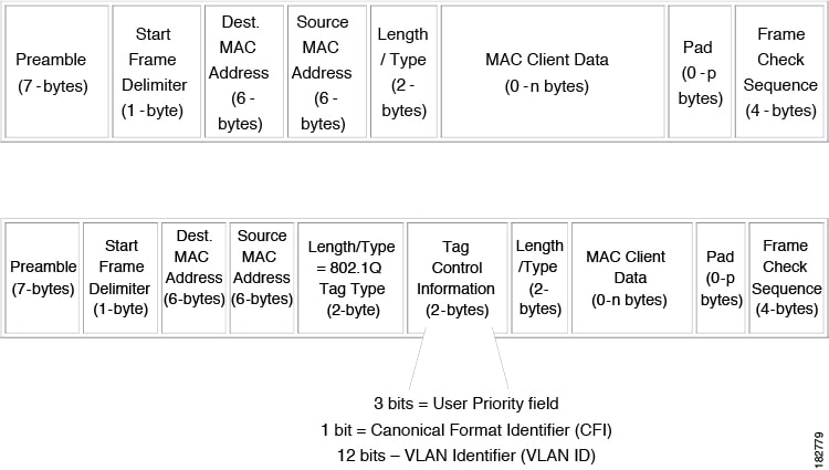
To correctly deliver the traffic on a trunk port with several VLANs, the device uses the IEEE 802.1Q encapsulation, or tagging, method that uses a tag that is inserted into the frame header. This tag carries information about the specific VLAN to which the frame and packet belong. This method allows packets that are encapsulated for several different VLANs to traverse the same port and maintain traffic separation between the VLANs. Also, the encapsulated VLAN tag allows the trunk to move traffic end-to-end through the network on the same VLAN.

Figure 2. Header Without and With 802.1Q Tag


Drop Eligible Indicator

When Nexus 9000 switch receives a frame with DEI bit set to 1, it is forwarded as is to the next hop. For example, if the next hop is Nexus 6000, it drops frames on receiving a packet with the DEI bit set to 1 in the dot1q header.

Beginning with Cisco Nexus NX-OS release 10.2(3)F, the DEI bit is cleared whenever a frame is received with DEI bit set to 1.

The following is the configuration for resetting the DEI bit.
switch# conf t
Enter configuration commands, one per line. End with CNTL/Z.
switch(config)# system default reset-dei
switch(config)
The following is the configuration for setting the DEI bit.
switch# conf t
Enter configuration commands, one per line. End with CNTL/Z.
switch(config)# no system default reset-dei
switch(config)

Access VLANs

When you configure a port in access mode, you can specify which VLAN will carry the traffic for that interface. If you do not configure the VLAN for a port in access mode, or an access port, the interface carries traffic for the default VLAN (VLAN1).

You can change the access port membership in a VLAN by specifying the new VLAN. You must create the VLAN before you can assign it as an access VLAN for an access port. If you change the access VLAN on an access port to a VLAN that is not yet created, the system shuts that access port down.

If an access port receives a packet with an 802.1Q tag in the header other than the access VLAN value, that port drops the packet without learning its MAC source address.

Native VLAN IDs for Trunk Ports

A trunk port can carry nontagged packets simultaneously with the 802.1Q tagged packets. When you assign a default port VLAN ID to the trunk port, all untagged traffic travels on the default port VLAN ID for the trunk port, and all untagged traffic is assumed to belong to this VLAN. This VLAN is referred to as the native VLAN ID for a trunk port. That is, the native VLAN ID is the VLAN that carries untagged traffic on trunk ports.


Note


Native VLAN ID numbers must match on both ends of the trunk.


The trunk port sends an egressing packet with a VLAN that is equal to the default port VLAN ID as untagged; all the other egressing packets are tagged by the trunk port. If you do not configure a native VLAN ID, the trunk port uses the default VLAN.


Note


You cannot use a Fibre Channel over Ethernet (FCoE) VLAN as a native VLAN for an Ethernet trunk switchport.


Tagging Native VLAN Traffic

The Cisco software supports the IEEE 802.1Q standard on trunk ports. In order to pass untagged traffic through the trunk ports, you must create a VLAN that does not tag any packets (or you can use the default VLAN). Untagged packets can pass through trunk ports and access ports.

However, all packets that enter the device with an 802.1Q tag that matches the value of the native VLAN on the trunk are stripped of any tagging and egress the trunk port as untagged packets. This situation can cause problems because you may want to retain the tagging on packets on the native VLAN for the trunk port.

You can configure the device to drop all untagged packets on the trunk ports and to retain the tagging of packets entering the device with 802.1Q values that are equal to that of the native VLAN ID. All control traffic still passes on the native VLAN. This configuration is global; trunk ports on the device either do or do not retain the tagging for the native VLAN.

Allowed VLANs

By default, a trunk port sends traffic to and receives traffic from all VLANs. All VLAN IDs are allowed on each trunk. However, you can remove VLANs from this inclusive list to prevent traffic from the specified VLANs from passing over the trunk. Later, you can add any specific VLANs that you may want the trunk to carry traffic for back to the list.

To partition the Spanning Tree Protocol (STP) topology for the default VLAN, you can remove VLAN1 from the list of allowed VLANs. Otherwise, VLAN1, which is enabled on all ports by default, will have a very big STP topology, which can result in problems during STP convergence. When you remove VLAN1, all data traffic for VLAN1 on this port is blocked, but the control traffic continues to move on the port.


Note


See the Cisco Nexus 9000 Series NX-OS Layer 2 Switching Configuration Guide for more information about STP.


Note


You can change the block of VLANs reserved for internal use. See the Cisco Nexus 9000 Series NX-OS Layer 2 Switching Configuration Guide for more information about changing the reserved VLANs.


Switchport Isolated for up to 3967 VLANs on Trunk Interfaces

Trunk interface can carry multiple VLANs, where a trunk interface that is configured in switchport isolated mode allows you to configure multiple VLANs per interface. Sometimes, you may require higher number VLANs per port. The scale of logical ports of Per-VLAN Spanning Tree (PVST) and virtual ports of Multiple Spanning Tree (MST) can be limiting. By configuring switchport isolated on a trunk interface, you can configure up to 48 interfaces with up to 3967 VLANs per port, on switches in Cisco Nexus 9000 portfolio.

When you change the member VLANs on the isolated interfaces, all VLANs on these interfaces get moved to forwarding state. Switchport isolated feature is supported only on the host interfaces, because no spanning tree is running on these ports (the switch doesn't send STP BPDUs), connecting other network devices may create a loop in the network. Switchport isolated feature is supported on physical interfaces, port channels, and vPC. Switchport isolated feature has the following restrictions:

  • Supports Per-VLAN Rapid Spanning Tree (PVRST) and isolated VLANs. It allows some ports to be in isolated mode, and some ports run Rapid Per-VLAN Spanning Tree (RPVST) with the same VLANs.

  • Rapid Spanning Tree (RSTP) running on other ports with same VLAN is supported.

  • Is not supported on FEX HIF, FEX fabric interface, on an interface when another network device is connected.

  • Supports up to 48 ports configured with up to 3967 VLANs.

  • When used in vPC environment if configured inconsistently will trigger vPC type 1 constancy checks.

  • Port channel members are required to have the same switchport isolated configuration.

Beginning with 7.0(3)I4(1), the switchport isolated feature allows disabling STP on an interface. Using this feature allows a maximum number of 4K VLAN * 48 virtual ports. Configuring the switchport isolated feature places all 4K VLANS in forwarding state for that port. (Removing a VLAN does not bring down the logical port.)

The switchport isolated feature allows disabling STP on an interface. Using this feature allows a maximum number of 4K VLAN * 48 virtual ports. Configuring the switchport isolated feature places all 4K VLANS in forwarding state for that port. (Removing a VLAN does not bring down the logical port.)

The feature is supported on MSTP modes. It is also supported on physical interfaces and port-channels (including vPC).


Note


The switchport isolated feature supports a maximum of 48 ports with 4K VLANs in MSTP modes.


In vPC configurations, the Type-1 consistency check is performed between vPC peers. If the check result is inconsistent, the secondary vPC is brought down while the primary continues to stay up.


Note


Spanning-tree is not notified during logical bring up/bring down when using the switchport isolated feature.


Default Interfaces

You can use the default interface feature to clear the configured parameters for both physical and logical interfaces such as the Ethernet, loopback, VLAN network, tunnel, and the port-channel interface.


Note


A maximum of eight ports can be selected for the default interface. The default interfaces feature is not supported for management interfaces because the device could go to an unreachable state.


Switch Virtual Interface and Autostate Behavior

In Cisco NX-OS, a switch virtual interface (SVI) represents a logical interface between the bridging function and the routing function of a VLAN in the device.

The operational state of this interface is governed by the state of the various ports in its corresponding VLAN. An SVI interface on a VLAN comes up when at least one port in that VLAN is in the Spanning Tree Protocol (STP) forwarding state. Similarly, this interface goes down when the last STP forwarding port goes down or goes to another STP state.

SVI Autostate Exclude

Typically, when a VLAN interface has multiple ports in the VLAN, the SVI goes to the down state when all the ports in the VLAN go down. You can use the SVI autostate exclude feature to exclude specific ports and port channels while defining the status of the SVI (up or down) even if it belongs to the same VLAN. For example, even if the excluded port or port channel is in the up state and other ports are in the down state in the VLAN, the SVI state is changed to down.


Note


You can use the SVI autostate exclude feature only for switched physical Ethernet ports and port channels.


SVI Autostate Disable

You can also use the SVI for inband management of a device. Specifically, you can configure the autostate disable feature to keep an SVI up even if no interface is up in the corresponding VLAN. You can configure this feature for the system (for all SVIs) or for an individual SVI.

You can configure the autostate disable feature to keep an SVI up even if no interface is up in the corresponding VLAN. You can configure this feature for the system (for all SVIs) or for an individual SVI.

SVI Autostate Enable/Disable

You can also use the SVI for inband management of a device by enabling or disabling the SVI autostate feature. Specifically, you can configure the autostate disable feature to keep an SVI up even if no interface is up in the corresponding VLAN. You can configure this feature for the system (for all SVIs) or for an individual SVI.

Virtualization Support

All ports in the same trunk must be in the same VDC, and trunk ports cannot carry VLANs from different VDCs.

Counter Values

See the following information on the configuration, packet size, incremented counter values, and traffic.

Configuration

Packet Size

Incremented Counters

Traffic

L2 port – without any MTU configuration

6400 and 10000

Jumbo, giant, and input error

Dropped

L2 port – with jumbo MTU 9216 in network-qos configuration

6400

Jumbo

Forwarded

L2 port – with jumbo MTU 9216 in network-qos configuration

10000

Jumbo, giant, and input error

Dropped

Layer 3 port with default Layer 3 MTU and jumbo MTU 9216 in network-qos configuration

6400

Jumbo

Packets are punted to the CPU (subjected to CoPP configs), get fragmented, and then they are forwarded by the software.

Layer 3 port with default Layer 3 MTU and jumbo MTU 9216 in network-qos configuration

6400

Jumbo

Packets are punted to the CPU (subjected to CoPP configs), get fragmented, and then they are forwarded by the software.

Layer 3 port with default Layer 3 MTU and jumbo MTU 9216 in network-qos configuration

10000

Jumbo, giant, and input error

Dropped

Layer 3 port with jumbo Layer 3 MTU and jumbo MTU 9216 in network-qos configuration

6400

Jumbo

Forwarded without any fragmentation.

Layer 3 port with jumbo Layer 3 MTU and jumbo MTU 9216 in network-qos configuration

10000

Jumbo, giant, and input error

Dropped

Layer 3 port with jumbo Layer 3 MTU and default L2 MTU configuration

6400 and 10000

Jumbo, giant, and input error

Dropped


Note


  • Under 64 bytes packet with good CRC–The short frame counter increments.

  • Under 64 bytes packet with bad CRC–The runts counter increments.

  • Greater than 64 bytes packet with bad CRC–The CRC counter increments.


Prerequisites for Layer 2 Interfaces

Layer 2 interfaces have the following prerequisites:

  • By default, Cisco NX-OS configures Layer 3 parameters. If you want to configure Layer 2 parameters, you need to switch the port mode to Layer 2. You can change the port mode by using the switchport command.

  • You must configure the port as a Layer 2 port before you can use the switchport mode command. By default, all ports on the device are Layer 3 ports. By default, all ports on the Cisco Nexus 9504 and Cisco Nexus 9508 devices are Layer 2 ports.

Guidelines and Limitations for Layer 2 Interfaces

VLAN trunking has the following configuration guidelines and limitations:

  • Cisco Nexus 9000 Series switches have the vlan dot1q tag native command that can be configured globally. This tags the native VLAN on the configured trunk ports. However, connected switches such as Catalyst 6500 or third-party switches, probably would not have a similar configuration enabled. This could result in unexpected behaviors. Therefore, it is recommended to have the vlan dot1q tag native command disabled in case the connected switch does not have it configured.

  • BFD session on SVI interface with native VLAN is not supported with vlan dot1q tag native command configuration on Cisco Nexus 9300-X Cloud Scale Switches.

  • Auto-negotiation is not supported on Cisco Nexus 9508 platform switches with N9K-X9636C-R, N9K-X9636C-RX, and N9K-X9636Q-R lines cards.

  • Auto-negotiation is supported only on 10/25/40/100 direct attach copper cables.

  • Auto-negotiation cannot be disabled on BaseT ports.

  • Auto-negotiation is not used on fiber based optics.

  • Beginning with Cisco NX-OS Release 9.2(1), the Cisco Nexus 9508 platform switches with N9K-X96136YC-R line cards support 1 Gigabit speed on all 48 ports. However, because the auto negotiation is not supported, 1000BASE-T SFPs links comes up even the cable is removed.

  • Beginning with Cisco NX-OS Release 9.2(1), auto negotiation on native 25G ports is supported on Cisco Nexus N9K-X97160YC-EX, N9K-C93180YC-FX, N9K-C93240YC-FX2 and N9K-C93240YC-FX2-Z switches.


    Note


    Auto negotiation is not supported on Cisco Nexus N9K-C92300YC switch


  • show commands with the internal keyword are not supported.

  • Auto-negotiation is not supported on 25-G Ethernet transceiver modules on Cisco Nexus 9200 and 9300-FX platform switches, and Cisco Nexus 9500 platform switches that use N9K-X9700-EX line cards.

  • On the Cisco Nexus 9364C switches, auto-negotiation might not work on ports 49-64 when bringing up 100G links using the QSFP-100G-CR4 cable. The workaround for this issue is that you must hard code the speed on ports 49-64 and disable auto-negotiation.

  • On Cisco Nexus 9300 platform switches, a unicast ARP request to SVI is flooded to the other ports within the VLAN.

  • On Cisco Nexus 9300 platform switches, a unicast ARP request to SVI is flooded to the other ports within the VLAN.

  • ASE2 and ASE3 based Cisco Nexus 9000 Series switches acting as transit switches do not preserve the inner tag for double-tagged packets.

    The following CLI is mandatory only on LSE based Cisco Nexus 9000 Series switches. For seamless packet forwarding and preservation of all VLAN tags on pure transit boxes in the SP cloud that have no Q-in-Q encapsulation or decapsulation requirement, configure the CLI command, system dot1q-tunnel transit . To remove the CLI, use no system dot1q-tunnel transit CLI command.

    The caveats with the CLI that is executed on the switches are:

    • L2 frames that egress out of the trunk ports are tagged even on the native VLAN on the port.

    • Any other tunneling mechanism, for example, VXLAN and MPLS does not work with the CLI configured.

  • A port can be either a Layer 2 or a Layer 3 interface; it cannot be both simultaneously.

  • When you change a Layer 3 port to a Layer 2 port or a Layer 2 port to a Layer 3 port, all layer-dependent configuration is lost. When you change an access or trunk port to a Layer 3 port, all information about the access VLAN, native VLAN, allowed VLANs, and so forth, is lost.

  • Do not connect devices with access links because access links may partition a VLAN.

  • When connecting Cisco devices through an 802.1Q trunk, make sure that the native VLAN for an 802.1Q trunk is the same on both ends of the trunk link. If the native VLAN on one end of the trunk is different from the native VLAN on the other end, spanning tree loops might result.

  • Disabling spanning tree on the native VLAN of an 802.1Q trunk without disabling spanning tree on every VLAN in the network can cause spanning tree loops. You must leave spanning tree enabled on the native VLAN of an 802.1Q trunk. If you cannot leave spanning tree enabled, you must disable spanning tree on every VLAN in the network. Make sure that your network has no physical loops before you disable spanning tree.

  • When you connect two Cisco devices through 802.1Q trunks, the devices exchange spanning tree bridge protocol data units (BPDUs) on each VLAN allowed on the trunks. The BPDUs on the native VLAN of the trunk are sent untagged to the reserved IEEE 802.1D spanning tree multicast MAC address (01-80-C2-00-00-00). The BPDUs on all other VLANs on the trunk are sent tagged to the reserved Cisco Shared Spanning Tree (SSTP) multicast MAC address (01-00-0c-cc-cc-cd).

  • Non-Cisco 802.1Q devices maintain only a single instance of spanning tree (the Mono Spanning Tree) that defines the spanning tree topology for all VLANs. When you connect a Cisco switch to a non-Cisco switch through an 802.1Q trunk, the Mono Spanning Tree of the non-Cisco switch and the native VLAN spanning tree of the Cisco switch combine to form a single spanning tree topology known as the Common Spanning Tree (CST).

  • Because Cisco devices transmit BPDUs to the SSTP multicast MAC address on VLANs other than the native VLAN of the trunk, non-Cisco devices do not recognize these frames as BPDUs and flood them on all ports in the corresponding VLAN. Other Cisco devices connected to the non-Cisco 802.1Q cloud receive these flooded BPDUs. This BPDU reception allows Cisco switches to maintain a per-VLAN spanning tree topology across a cloud of non-Cisco 802.1Q devices. The non-Cisco 802.1Q cloud that separates the Cisco devices is treated as a single broadcast segment between all devices connected to the non-Cisco 802.1Q cloud through 802.1Q trunks.

  • Make certain that the native VLAN is the same on all of the 802.1Q trunks that connect the Cisco devices to the non-Cisco 802.1Q cloud.

  • If you are connecting multiple Cisco devices to a non-Cisco 802.1Q cloud, all of the connections must be through 802.1Q trunks. You cannot connect Cisco devices to a non-Cisco 802.1Q cloud through access ports because doing so places the access port on the Cisco device into the spanning tree “port inconsistent” state and no traffic will pass through the port.

  • You can group trunk ports into port-channel groups, but all trunks in the group must have the same configuration. When a group is first created, all ports follow the parameters set for the first port to be added to the group. If you change the configuration of one of these parameters, the device propagates that setting to all ports in the group, such as the allowed VLANs and the trunk status. For example, if one port in a port group ceases to be a trunk, all ports cease to be trunks.

  • If you try to enable 802.1X on a trunk port, an error message appears, and 802.1X is not enabled. If you try to change the mode of an 802.1X-enabled port to trunk, the port mode is not changed.

  • Only ingress unicast packet counters are supported for SVI counters.

  • When MAC addresses are cleared on a VLAN with the clear mac address-table dynamic command, the dynamic ARP (Address Resolution Protocol) entries on that VLAN are refreshed.

  • If a static ARP entry exists on the VLAN and no MAC address to port mapping is present, the supervisor may generate an ARP request to learn the MAC address. Upon learning the MAC address, the adjacency entry points to the correct physical port.

  • Cisco NX-OS does not support transparent bridging between two VLANs when one of the SVIs is on the Cisco Nexus 9000 using the BIA MAC (burned-in MAC address). This occurs when the BIA MAC is shared between SVIs/VLANs. A MAC, different from the BIA MAC, can be configured under the SVI for transparent bridging to work properly.


    Note


    This behavior is applicable to Cisco Nexus 9300 Switches (Network Forwarding Engine) and Cisco Nexus 9500 Switches with 95xx,96xx,94xx line cards. This behavior is not applicable to Cisco Nexus 9200 Switches, Cisco Nexus 9300-EX and Cisco Nexus 9500 Switches with 9700-EX line cards.


  • Port-local VLANs do not support Fabric Extenders (FEX).

  • On Cisco Nexus 9364C switches, auto-negotiation may not work on ports 49-64 when bringing up 100G links using QSFP-100G-CR4 cable. To workaround this issue, you must hard-code the speed on ports 49-64 and disable auto-negotiation.

  • You may get an error message when you attempt to configure the interface mode to trunk and trunk VLANs simultaneously. On Cisco NX-OS interfaces, the default value of interface mode is access. To implement any trunk related configurations, you must first change the interface mode to trunk and then configure the trunk VLAN ranges.

  • On a vPC set up, if the VLAN is a vPC VLAN, the MAC address limit for VLAN and system is not supported.

  • All the existing MACs may be flushed and relearnt, when the MAC address table limit is enabled for an interface, VLAN, and/or system.

  • MAC address table limit enabled on vPC PO must be consistent across both the peers.

  • If you configure MAC address table limit on system, port and VLAN at a time or in any combinations, each one of them will limit the MACs as they are configured. The preference will always be in the following order:

    • Port

    • VLAN

    • System

  • MAC address table limit is not supported on vPC Peer-Links.

  • Minimum configurable MAC address table limit is 100 and the maximum configurable limit is 196000.

  • When an interface or a VLAN is removed from the set-up, the associated MAC address table limit configuration also gets removed.

  • MAC address table limits are not supported on PVLAN interface types.

  • When the MAC address table limit exceeds, it floods the traffic, by default.

  • When you plug-in a FET-10G Fabric Extender Transceiver in a port on a Cisco Nexus N9K-C93180YC-FX3S switch or Cisco Nexus 9500 switch with N9K-X9716D-GX line card, you may see the links go up even if the ports are not converted to fabric ports using the command switchport mode fex-fabric .

  • Beginning with Cisco NX-OS Release 10.2(1q)F, Layer 2 (L2) interfaces are supported on the N9K-C9332D-GX2B platform switches.

  • Beginning with Cisco NX-OS Release 10.1(2), Layer 2 Interfaces are supported on Cisco Nexus N9K-X9624D-R2 line cards.

  • For Cisco Nexus Release 9.3(x) the Cisco Nexus N9K-C9316D-GX, N9K-C93600CD-GX switches have the following guidelines and limitations:

    • Beginning with Cisco Nexus NX-OS Release 10.1(2) Auto negotiation is supported for Speed 40G and 100G on NX-OS N9K-C93600CD-GX, N9K-C9316D-GX and N9K-C9364C-GX

    • Cisco Nexus 9300-GX platform switches do not support FC-FEC on the second lane of the 50Gx2 breakout port. The second breakout port will not link up when 50Gx2 breakout is configured. Workaround: Configure RS-FEC with 50Gx2 breakout.

    • For N9K-C9316D-GX: Ports 1-16 support 400G/100G/40G and 10G with QSA.

    • For N9K-C93600CD-GX: For ports 1-24, every four ports (1-4, 5-8, 9-12, and so on, referred to as a "quad") operate at the same speed. All the ports in a quad operate in 10G, or 40G or 100G. Mixed speed is not supported within the same quad. With QSA, all ports in a quad can operate at 10G speed. Port 25-26 should operate at same speed and port 27-28 should operate at same speed. Mismatch of speed on ports 25-26 or 27-28 is not supported.

    N9K-C9364C-GX has the following guidelines and limitations:

    • For ports 1-64, every four ports (1-4, 5-8, 9-12, and so on, referred to as a "quad") operates at same speed. All the ports in a quad operate in 10G, or 40G or 100G.

    • Mixed speed is not supported within the same quad.

    • With QSA all ports in a quad can operate at 10G speed.

  • Beginning with Cisco NX-OS Release 10.4(1)F, L2 forwarding is supported on the Cisco Nexus 9332D-H2R platform switches.

  • Beginning with Cisco NX-OS Release 10.4(2)F, L2 forwarding is supported on the Cisco Nexus 93400LD-H1 platform switches.

  • Beginning with Cisco NX-OS Release 10.4(3)F, L2 forwarding is supported on the Cisco Nexus N9KC9364C-H1 platform switches.

  • Beginning with Cisco NX-OS Release 10.4(1)F, L2 infra is supported on the Cisco Nexus 9332D-H2R platform switches.

  • Beginning with Cisco NX-OS Release 10.4(2)F, L2 infra is supported on the Cisco Nexus 93400LD-H1 platform switches.

  • Beginning with Cisco NX-OS Release 10.4(3)F, L2 infra is supported on the Cisco Nexus N9KC9364C-H1 platform switches.

  • Beginning with Cisco NX-OS Release 10.4(2)F, SFP-25G-ER-I transceiver module is supported on the Cisco Nexus C93180YC-FX3 switch.

  • Beginning with Cisco NX-OS Release 10.4(3)F, the breakout (4x10G, 4x25G, and 4x100G) ports support is provided on Cisco Nexus X98900CD-A switch.

    The 4x25 Breakout is supported only on below ports. Supported ports are 2,3,5,6,8,9,11,12,14,15,17,18,20,21,23,24,26,27,29,30,32,33,35,36,38,39,41,42,44,45,47,48

  • Beginning with Cisco NX-OS Release 10.4(3)F, X98900CD-A and all ports for X9836DM-A supports 2x200GE breakout with 400EG ports.

  • Beginning with Cisco NX-OS Release 10.4(3)F, X98900CD-A is supported on 3, 6, 9, 12, 15, 18, 21, 27, 30, 33, 36, 39, 42, and 45 ports.


Note


In Cisco NX-OS Release 10.2(2)F, the link up time of SFP-10G-T-X module in N9K-C93180YC-FX3S, N9K-C93180YC-FX3 switches is 13 seconds


Default Settings for Layer 2 Interfaces

The following table lists the default settings for device access and trunk port mode parameters.

Table 1. Default Access and Trunk Port Mode Parameters

Parameters

Default

Switchport mode

Access

Allowed VLANs

1 to 3967, 4048 to 4094

Access VLAN ID

VLAN1

Native VLAN ID

VLAN1

Native VLAN ID tagging

Disabled

Administrative state

Shut

Table 2. Default Access and Trunk Port Mode Parameters (7.0(3)I1(2) and earlier)

Parameters

Default

Switchport mode

Access

Allowed VLANs

1 to 3967, 4048 to 4094

Access VLAN ID

VLAN1

Native VLAN ID

VLAN1

Native VLAN ID tagging

Disabled

Administrative state

Shut

Table 3. Default Access and Trunk Port Mode Parameters (7.0(3)I2(1) and later)

Parameters

Default

Switchport mode

Access

Allowed VLANs

1 to 3967, 4048 to 4094

Access VLAN ID

VLAN1

Native VLAN ID

VLAN1

Native VLAN ID tagging

Disabled

Administrative state

Shut

SVI autostate

Enabled

Configuring Access and Trunk Interfaces


Note


If you are familiar with the Cisco IOS CLI, be aware that the Cisco NX-OS commands for this feature might differ from the Cisco IOS commands that you would use.


Guidelines for Configuring Access and Trunk Interfaces

All VLANs on a trunk must be in the same VDC.

Configuring a VLAN Interface as a Layer 2 Access Port

You can configure a Layer 2 port as an access port. An access port transmits packets on only one, untagged VLAN. You specify which VLAN traffic that the interface carries, which becomes the access VLAN. If you do not specify a VLAN for an access port, that interface carries traffic only on the default VLAN. The default VLAN is VLAN1.

The VLAN must exist before you can specify that VLAN as an access VLAN. The system shuts down an access port that is assigned to an access VLAN that does not exist.

Before you begin

Ensure that you are configuring a Layer 2 interface.

SUMMARY STEPS

  1. configure terminal
  2. interface ethernet {{type slot/port} | {port-channel number}}
  3. switchport mode [access | trunk]
  4. switchport access vlan vlan-id
  5. exit
  6. show interface
  7. no shutdown
  8. copy running-config startup-config

DETAILED STEPS

  Command or Action Purpose

Step 1

configure terminal

Example:

switch# configure terminal
switch(config)#

Enters global configuration mode.

Step 2

interface ethernet {{type slot/port} | {port-channel number}}

Example:

switch(config)# interface ethernet 3/1
switch(config-if)# 

Specifies an interface to configure, and enters interface configuration mode.

Step 3

switchport mode [access | trunk]

Example:

switch(config-if)# switchport mode access

Sets the interface as a nontrunking nontagged, single-VLAN Layer 2 interface. An access port can carry traffic in one VLAN only. By default, an access port carries traffic for VLAN1; to set the access port to carry traffic for a different VLAN, use the switchport access vlan command.

Step 4

switchport access vlan vlan-id

Example:

switch(config-if)# switchport access vlan 5

Specifies the VLAN for which this access port will carry traffic. If you do not enter this command, the access port carries traffic on VLAN1 only; use this command to change the VLAN for which the access port carries traffic.

Step 5

exit

Example:

switch(config-if)# exit
switch(config)# 

Exits the interface configuration mode.

Step 6

show interface

Example:

switch# show interface

(Optional) Displays the interface status and information.

Step 7

no shutdown

Example:

switch# configure terminal
switch(config)# int e3/1
switch(config-if)# no shutdown

(Optional) Clears the errors on the interfaces and VLANs where policies correspond with hardware policies. This command allows policy programming to continue and the port to come up. If policies do not correspond, the errors are placed in an error-disabled policy state.

Step 8

copy running-config startup-config

Example:

switch(config)# copy running-config startup-config  

(Optional) Copies the running configuration to the startup configuration.

Example

This example shows how to set Ethernet 3/1 as a Layer 2 access port that carries traffic for VLAN 5 only:

switch# configure terminal 
switch(config)# interface ethernet 3/1
switch(config-if)# switchport mode access
switch(config-if)# switchport access vlan 5
switch(config-if)#

Configuring Access Host Ports


Note


You should apply the switchport host command only to interfaces that are connected to an end station.


You can optimize the performance of access ports that are connected to end stations by simultaneously setting that port as an access port. An access host port handles the STP like an edge port and immediately moves to the forwarding state without passing through the blocking and learning states. Configuring an interface as an access host port also disables port channeling on that interface.


Note


See “Configuring Port Channels” section and the Cisco Nexus 9000 Series NX-OS Layer 2 Switching Configuration Guide for information about port-channel interfaces


Before you begin

Ensure that you are configuring the correct interface to an interface that is an end station.

SUMMARY STEPS

  1. configure terminal
  2. interface ethernet type slot/port
  3. switchport host
  4. exit
  5. show interface
  6. no shutdown
  7. copy running-config startup-config

DETAILED STEPS

  Command or Action Purpose

Step 1

configure terminal

Example:

switch# configure terminal
switch(config)#

Enters global configuration mode.

Step 2

interface ethernet type slot/port

Example:

switch(config)# interface ethernet 3/1
switch(config-if)# 

Specifies an interface to configure, and enters interface configuration mode.

Step 3

switchport host

Example:

switch(config-if)# switchport host

Sets the interface to be an access host port, which immediately moves to the spanning tree forwarding state and disables port channeling on this interface.

Note


Apply this command only to end stations.

Step 4

exit

Example:

switch(config-if-range)# exit
switch(config)# 

Exits the interface mode.

Step 5

show interface

Example:

switch# show interface

(Optional) Displays the interface status and information.

Step 6

no shutdown

Example:

switch# configure terminal
switch(config)# int e3/1
switch(config-if)# no shutdown

(Optional) Clears the errors on the interfaces and VLANs where policies correspond with hardware policies. This command allows policy programming to continue and the port to come up. If policies do not correspond, the errors are placed in an error-disabled policy state.

Step 7

copy running-config startup-config

Example:

switch(config)# copy running-config startup-config  

(Optional) Copies the running configuration to the startup configuration.

Example

This example shows how to set Ethernet 3/1 as a Layer 2 access port with PortFast enabled and port channel disabled:

switch# configure terminal 
switch(config)# interface ethernet 3/1
switch(config-if)# switchport host
switch(config-if)#

Configuring Trunk Ports

You can configure a Layer 2 port as a trunk port. A trunk port transmits untagged packets for one VLAN plus encapsulated, tagged, packets for multiple VLANs. (See the “IEEE 802.1Q Encapsulation” section for information about encapsulation.)


Note


The device supports 802.1Q encapsulation only.


Before you begin

Before you configure a trunk port, ensure that you are configuring a Layer 2 interface.

SUMMARY STEPS

  1. configure terminal
  2. interface {type slot/port | port-channel number}
  3. switchport mode [access | trunk]
  4. exit
  5. show interface
  6. no shutdown
  7. copy running-config startup-config

DETAILED STEPS

  Command or Action Purpose

Step 1

configure terminal

Example:

switch# configure terminal
switch(config)#

Enters global configuration mode.

Step 2

interface {type slot/port | port-channel number}

Example:

switch(config)# interface ethernet 3/1
switch(config-if)# 

Specifies an interface to configure, and enters interface configuration mode.

Step 3

switchport mode [access | trunk]

Example:

switch(config-if)# switchport mode trunk

Sets the interface as a Layer 2 trunk port. A trunk port can carry traffic in one or more VLANs on the same physical link (VLANs are based on the trunk-allowed VLANs list). By default, a trunk interface can carry traffic for all VLANs. To specify that only certain VLANs are allowed on the specified trunk, use the switchport trunk allowed vlan command.

Step 4

exit

Example:

switch(config-if)# exit
switch(config)# 

Exits the interface mode.

Step 5

show interface

Example:

switch# show interface

(Optional) Displays the interface status and information.

Step 6

no shutdown

Example:

switch# configure terminal
switch(config)# int e3/1
switch(config-if)# no shutdown

(Optional) Clears the errors on the interfaces and VLANs where policies correspond with hardware policies. This command allows policy programming to continue and the port to come up. If policies do not correspond, the errors are placed in an error-disabled policy state.

Step 7

copy running-config startup-config

Example:

switch(config)# copy running-config startup-config  

(Optional) Copies the running configuration to the startup configuration.

Example

This example shows how to set Ethernet 3/1 as a Layer 2 trunk port:

switch# configure terminal 
switch(config)# interface ethernet 3/1
switch(config-if)# switchport mode trunk
switch(config-if)#

Configuring the Native VLAN for 802.1Q Trunking Ports

You can configure the native VLAN for 802.1Q trunk ports. If you do not configure this parameter, the trunk port uses the default VLAN as the native VLAN ID.


Note


You cannot configure an FCoE VLAN as a native VLAN for an Ethernet interface.


SUMMARY STEPS

  1. configure terminal
  2. interface {{type slot/port} | {port-channel number}}
  3. switchport trunk native vlan vlan-id
  4. exit
  5. show vlan
  6. no shutdown
  7. copy running-config startup-config

DETAILED STEPS

  Command or Action Purpose

Step 1

configure terminal

Example:

switch# configure terminal
switch(config)#

Enters global configuration mode.

Step 2

interface {{type slot/port} | {port-channel number}}

Example:

switch(config)# interface ethernet 3/1
switch(config-if)# 

Specifies an interface to configure, and enters interface configuration mode.

Step 3

switchport trunk native vlan vlan-id

Example:

switch(config-if)# switchport trunk native vlan 5

Sets the native VLAN for the 802.1Q trunk. Valid values are from 1 to 4094, except those VLANs reserved for internal use. The default value is VLAN1.

Step 4

exit

Example:

switch(config-if-range)# exit
switch(config)# 

Exits interface configuration mode.

Step 5

show vlan

Example:

switch# show vlan

(Optional) Displays the status and information of VLANs.

Step 6

no shutdown

Example:

switch# configure terminal
switch(config)# int e3/1
switch(config-if)# no shutdown

(Optional) Clears the errors on the interfaces and VLANs where policies correspond with hardware policies. This command allows policy programming to continue and the port to come up. If policies do not correspond, the errors are placed in an error-disabled policy state.

Step 7

copy running-config startup-config

Example:

switch(config)# copy running-config startup-config  

(Optional) Copies the running configuration to the startup configuration.

Example

This example shows how to set the native VLAN for the Ethernet 3/1, Layer 2 trunk port to VLAN 5:

switch# configure terminal 
switch(config)# interface ethernet 3/1
switch(config-if)# switchport trunk native vlan 5
switch(config-if)#

Configuring the Allowed VLANs for Trunking Ports

You can specify the IDs for the VLANs that are allowed on the specific trunk port.


Note


The switchport trunk allowed vlan vlan-list command replaces the current VLAN list on the specified port with the new list. You are prompted for confirmation before the new list is applied.

If you are doing a copy and paste of a large configuration, you might see some failures because the CLI is waiting for a confirmation before accepting other commands. To avoid this problem, you can disable prompting by using the terminal dont-ask command before you paste the configuration.


Before you begin

Before you configure the allowed VLANs for the specified trunk ports, ensure that you are configuring the correct interfaces and that the interfaces are trunks.


Note


You can change the block of VLANs reserved for internal use. See the Cisco Nexus 9000 Series NX-OS Layer 2 Switching Configuration Guide for more information about changing the reserved VLANs.


SUMMARY STEPS

  1. configure terminal
  2. interface {ethernet slot/port | port-channel number}
  3. switchport trunk allowed vlan {vlan-list add vlan-list | all | except vlan-list | none | remove vlan-list}
  4. exit
  5. show vlan
  6. no shutdown
  7. copy running-config startup-config

DETAILED STEPS

  Command or Action Purpose

Step 1

configure terminal

Example:

switch# configure terminal
switch(config)#

Enters global configuration mode.

Step 2

interface {ethernet slot/port | port-channel number}

Example:

switch(config)# interface ethernet 3/1

Specifies an interface to configure, and enters interface configuration mode.

Step 3

switchport trunk allowed vlan {vlan-list add vlan-list | all | except vlan-list | none | remove vlan-list}

Example:

switch(config-if)# switchport trunk allowed vlan add 15-20

Sets the allowed VLANs for the trunk interface. The default is to allow all VLANs on the trunk interface: 1 to 3967 and 4048 to 4094. VLANs 3968 to 4047 are the default VLANs reserved for internal use by default. By default, all VLANs are allowed on all trunk interfaces.

The default reserved VLANs are 3968 to 4094, and you can change the block of reserved VLANs. See the Cisco Nexus 9000 Series NX-OS Layer 2 Switching Configuration Guide for more information.

Note


You cannot add internally allocated VLANs as allowed VLANs on trunk ports. The system returns a message if you attempt to list an internally allocated VLAN as an allowed VLAN.

Step 4

exit

Example:

switch(config-if)# exit
switch(config)# 

Exits the interface mode.

Step 5

show vlan

Example:

switch# show vlan

(Optional) Displays the status and information for VLANs.

Step 6

no shutdown

Example:

switch# configure terminal
switch(config)# int e3/1
switch(config-if)# no shutdown

(Optional) Clears the errors on the interfaces and VLANs where policies correspond with hardware policies. This command allows policy programming to continue and the port to come up. If policies do not correspond, the errors are placed in an error-disabled policy state.

Step 7

copy running-config startup-config

Example:

switch(config)# copy running-config startup-config  

(Optional) Copies the running configuration to the startup configuration.

Example

This example shows how to add VLANs 15 to 20 to the list of allowed VLANs on the Ethernet 3/1, Layer 2 trunk port:

switch# configure terminal 
switch(config)# interface ethernet 3/1
switch(config-if)# switchport trunk allowed vlan 15-20
switch(config-if)#

Configuring MAC Addresses Limitation on a Port

Beginning Cisco NX-OS Release 9.2(3), Cisco Nexus 9500 Series switches with N9K-X9636C-RX, N3K-C3636C-R and N3K-C36180YC-R line cards provides the ability to set an upper limit for the number of MAC addresses that can be learnt by each port. For example, if the specified VLAN limitation is 2000 MACs, the Layer 2 Forwarding Manager (L2FM) accepts the first 2000 MACs it receives and reject the remaining MACs. To configure MAC address limitation on an interface, follow these steps:

SUMMARY STEPS

  1. switch# configure terminal
  2. switch(config)# mac address-table limit interface port-channel value
  3. switch(config)# show mac address-table limit interf
  4. switch(config)# exit

DETAILED STEPS

  Command or Action Purpose

Step 1

switch# configure terminal

Enters global configuration mode.

Step 2

switch(config)# mac address-table limit interface port-channel value

Specifies an upper limit for MAC learning at port level.

Step 3

switch(config)# show mac address-table limit interf

Displays the list of interfaces on which the MAC limits are configured.

Step 4

switch(config)# exit

Exits configuration mode.

Example

This example shows how to configure the upper limit for MAC learning at port levels:

switch# configure terminal
switch(config)# mac address-table limit interface port-channel 2 1000
Configuring Mac address limit will result in flushing existing Macs in the specified VLAN/System.Proceed(yes/no)? [no]  yes
switch(config)# exit
This example shows how to display the MAC address limitations:

switch# configure terminal
switch(config)# show mac address-table limit interf
Interface    Conf Limit     Curr Count    Cfg Action    Currently
-----------    ------------   ---------     ---------    --------
Vlan1               196000              0           Flood         Flooding Unknown SA
Vlan341             196000              0           Flood         Flooding Unknown SA
Vlan342             196000              0           Flood         Flooding Unknown SA
Vlan343             196000              0           Flood         Flooding Unknown SA
Vlan344             196000              0           Flood         Flooding Unknown SA
Vlan345             196000              0           Flood         Flooding Unknown SA
Vlan346             196000              0           Flood         Flooding Unknown SA
Vlan347             196000              0           Flood         Flooding Unknown SA
Vlan348             196000              0           Flood         Flooding Unknown SA
Vlan349             196000              0           Flood         Flooding Unknown SA
Vlan350             196000              0           Flood         Flooding Unknown SA
port-channel1       196000              0           Flood         Flooding Unknown SA
port-channel2       1000                0           Flood         Flooding Unknown SA
port-channel11      196000              0           Flood         Flooding Unknown SA
port-channel12      196000              0           Flood         Flooding Unknown SA
port-channel13      196000              0           Flood         Flooding Unknown SA
port-channel601     196000              0           Flood         Flooding Unknown SA
port-channel603     196000              0           Flood         Flooding Unknown SA
port-channel888     196000              0           Flood         Flooding Unknown SA
Ethernet1/6         196000              0           Flood         Flooding Unknown SA
Ethernet1/15        196000              0           Flood         Flooding Unknown SA
Ethernet1/35        196000              0           Flood         Flooding Unknown SA
BF2(config)#                                           
switch(config)# exit

Configuring switchport isolated

Beginning with 7.0(3)I2(1), the switchport isolated feature is supported. Switchport isolated can be configured on an interface to accommodate up to 3967 VLANs on an interface. The interfaces that are configured with switchport isolated do not send STP BPDUs.

Switchport isolated can be configured on an interface to accommodate up to 3967 VLANs on an interface. The interfaces that are configured with switchport isolated do not send STP BPDUs.


Note


The switchport isolated mode is not supported on an interface that is connected to a FEX, a switch, router or any other networking devices. Switchport Isolated is not supported on the FEX HIF ports.


Note


Physical interfaces with different switchport isolated configuration are not allowed in a port-channel.


SUMMARY STEPS

  1. configure terminal
  2. interface {{ethernet slot/port} | {port-channel number}}
  3. switchport isolated
  4. show running-config interface port-channel port-channel-number

DETAILED STEPS

  Command or Action Purpose

Step 1

configure terminal

Example:

switch# configure terminal
switch(config)#

Enters global configuration mode.

Step 2

interface {{ethernet slot/port} | {port-channel number}}

Example:

switch(config)# interface ethernet 3/1
switch(config-if)# 

Specifies an interface to configure, and enters interface configuration mode.

Step 3

switchport isolated

Example:

switch(config-if)# switchport isolated

Enables the switchport isolated feature.

Step 4

show running-config interface port-channel port-channel-number

(Optional) Displays the interface status and information.

Configuring a Default Interface

The default interface feature allows you to clear the existing configuration of multiple interfaces such as Ethernet, loopback, VLAN network, port-channel, and tunnel interfaces. All user configuration under a specified interface will be deleted. You can optionally create a checkpoint before clearing the interface configuration so that you can later restore the deleted configuration.


Note


The default interface feature is not supported for management interfaces because the device could go to an unreachable state.

If the speed group is configured, the default interface command displays the following error:

Error: default interface is not supported as speed-group is configured

SUMMARY STEPS

  1. configure terminal
  2. default interface int-if [checkpoint name]
  3. exit
  4. show interface
  5. no shutdown

DETAILED STEPS

  Command or Action Purpose

Step 1

configure terminal

Example:

switch# configure terminal
switch(config)#

Enters global configuration mode.

Step 2

default interface int-if [checkpoint name]

Example:

switch(config)# default interface ethernet 3/1 checkpoint test8

Deletes the configuration of the interface and restores the default configuration. Use the ? keyword to display the supported interfaces.

Use the checkpoint keyword to store a copy of the running configuration of the interface before clearing the configuration.

Step 3

exit

Example:

switch(config)# exit
switch(config)# 

Exits global configuration mode.

Step 4

show interface

Example:

switch# show interface

(Optional) Displays the interface status and information.

Step 5

no shutdown

Example:

switch# configure terminal
switch(config)# int e3/1
switch(config-if)# no shutdown

(Optional) Clears the errors on the interfaces and VLANs where policies correspond with hardware policies. This command allows policy programming to continue and the port to come up. If policies do not correspond, the errors are placed in an error-disabled policy state.

Example

This example shows how to delete the configuration of an Ethernet interface while saving a checkpoint of the running configuration for rollback purposes:

switch# configure terminal 
switch(config)# default interface ethernet 3/1 checkpoint test8
.......Done 
switch(config)# 

Switching Between QSFP and SFP+ Ports

When you break out ports into the 10-GbE mode, you can switch between the first QSFP port and SFP+ ports 1 to 4. Either the first QSFP port or the four SFP+ ports can be active at any time. QSFP is the default port with an interface speed of 40 Gbps.

When the first QSFP port is in the 40-GbE mode, you cannot switch the port to four SFP+ ports and the first QSFP port will be active until you break out the port into the 10-GbE mode. This is because SFP+ ports do not support the 40-GbE mode.

SUMMARY STEPS

  1. switch# configure terminal
  2. switch(config)# [no] hardware profile front portmode qsfp | sfp-plus
  3. switch(config)# interface breakout module module number port port rangemap 10g-4x
  4. (Optional) switch(config)# copy running-config startup-config

DETAILED STEPS

  Command or Action Purpose

Step 1

switch# configure terminal

Enters global configuration mode.

Step 2

switch(config)# [no] hardware profile front portmode qsfp | sfp-plus

Activates the specified port mode.
  • qsfp —The front panel QSFP port is active
  • sfp-plus —The front panel SFP+ ports 1 to 4 are active

The no form of this command activates the QSFP port.

Note

 
If the first QSFP port speed is 40 Gbps, this command will run, but the SFP+ ports will not become active until after the speed is changed to 10 Gbps.

Step 3

switch(config)# interface breakout module module number port port rangemap 10g-4x

Enables you to configure the module in 10g mode. When you are changing the portmode from QSFP to SFP+, the hardware profile front portmode command takes effect only after breaking out the first QSFP port as displayed in this command.

Step 4

(Optional) switch(config)# copy running-config startup-config

(Optional)

Saves the change persistently through reboots and restarts by copying the running configuration to the startup configuration.

Example

This example shows how to change the portmode from QSFP to SFP+:

switch# show int e1/1 tranceiver
Ethernet1/1
transceiver is present
type is QSFP-40G-SR
name is CISCO
part number is AFBR-79EIPZ-CS1
revision is 02
serial number is AVP1645S1QT
nominal bitrate is 10300 MBit/sec per channel
Link length supported for 50/125um fiber is 30 m
Link length supported for 50/125um fiber is 100 m
cisco id is --
cisco extended id number is 16

switch# show running-config | inc portmode
hardware profile portmode 32X40G
hardware profile front portmode qsfp

switch# configure terminal
switch(config)# hardware profile front portmode sfp-plus
switch(config)# interface breakout module 1 port 1 map 10g-4x
switch(config)# copy running-config startup-config

This example shows how to make the QSFP port active:

switch# configure terminal
switch(config)# no hardware profile front portmode
switch(config)# copy running-config startup-config

Configuring SVI Autostate Exclude

Beginning with7.0(3)I2(1), you can configure the SVI Autostate Exclude feature on an Ethernet interface or a port channel. You can use the Autostate Exclude option to enable or disable the port from bringing up or down the SVI calculation and applying it to all VLANs that are enabled on the selected port. You can also use the SVI Autostate Exlude VLAN feature to exclude a VLAN from the autostate excluded interface.

You can configure the SVI Autostate Exclude feature on an Ethernet interface or a port channel. You can use the Autostate Exclude option to enable or disable the port from bringing up or down the SVI calculation and applying it to all VLANs that are enabled on the selected port. You can also use the SVI Autostate Exlude VLAN feature to exclude a VLAN from the autostate excluded interface.

SUMMARY STEPS

  1. configure terminal
  2. interface {{type slot/port} | {port-channel number}}
  3. switchport
  4. [no] switchport autostate exclude
  5. [no] switchport autostate exclude vlan {vlan id | all | except}
  6. exit
  7. show running-config interface {{type slot/port} | {port-channel number}}
  8. no shutdown
  9. copy running-config startup-config

DETAILED STEPS

  Command or Action Purpose

Step 1

configure terminal

Example:

switch# configure terminal
switch(config)#

Enters global configuration mode.

Step 2

interface {{type slot/port} | {port-channel number}}

Example:

switch(config)# interface ethernet 3/1
switch(config-if)# 

Specifies an interface to configure, and enters interface configuration mode.

Step 3

switchport

Example:

switch(config-if)# switchport

Sets the interface as a Layer 2 interface.

Step 4

[no] switchport autostate exclude

Example:

switch(config-if)# switchport autostate exclude

Excludes this port from the VLAN interface link-up calculation when there are multiple ports in the VLAN.

To revert to the default settings, use the no form of this command.

Step 5

[no] switchport autostate exclude vlan {vlan id | all | except}

Example:

switch(config-if)# switchport autostate exclude vlan 10

(Optional) Excludes a vlan or a set of vlans from the autostate-excluded interface. This will help to minimize any disruption to the system.

To revert to the default settings, use the no form of this command.

Step 6

exit

Example:

switch(config-if)# exit
switch(config)# 

Exits the interface configuration mode.

Step 7

show running-config interface {{type slot/port} | {port-channel number}}

Example:

switch(config)# show running-config interface ethernet 3/1

(Optional) Displays configuration information about the specified interface.

Step 8

no shutdown

Example:

switch# configure terminal
switch(config)# int e3/1
switch(config-if)# no shutdown

(Optional) Clears the errors on the interfaces and VLANs where policies correspond with hardware policies. This command allows policy programming to continue and the port to come up. If policies do not correspond, the errors are placed in an error-disabled policy state.

Step 9

copy running-config startup-config

Example:

switch(config)# copy running-config startup-config  

(Optional) Copies the running configuration to the startup configuration.

Example

This example shows how to exclude a port from the VLAN interface link-up calculation on the Cisco NX-OS device:

switch# configure terminal 
switch(config)# interface ethernet 3/1
switch(config-if)# switchport
switch(config-if)# switchport autostate exclude

This example shows how to exclude a VLAN from the auto-excluded interface:

switch# configure terminal 
switch(config)# interface ethernet 3/1
switch(config-if)# switchport
switch(config-if)# switchport autostate exclude
switch(config-if)# switchport autostate exclude vlan 10

Configuring SVI Autostate Disable for the System

You can configure the SVI autostate disable feature to keep an SVI up even if no interface is up in the corresponding VLAN. Use this procedure to configure this feature for the entire system.

You can manage an SVI with the SVI autostate feature. You can configure the SVI autostate disable feature to keep an SVI up even if no interface is up in the corresponding VLAN. (Similarly, configure the SVI autostate enable feature so an SVI goes down when no interface is up in the corresponding VLAN). Use this procedure to configure this feature for the entire system.


Note


The system default interface-vlan autostate command enables the SVI autostate feature.


SUMMARY STEPS

  1. configure terminal
  2. [no] system default interface-vlan autostate
  3. no shutdown
  4. show running-config [all]

DETAILED STEPS

  Command or Action Purpose

Step 1

configure terminal

Example:

switch# configure terminal
switch(config)#

Enters global configuration mode.

Step 2

[no] system default interface-vlan autostate

Example:

switch(config)# no system default interface-vlan autostate

Disables the default autostate behavior for the device.

Note


Use the system default interface-vlan autostate command to enable the autostate behavior for the device.

Step 3

no shutdown

Example:

switch# configure terminal
switch(config)# int e3/1
switch(config-if)# no shutdown

(Optional) Clears the errors on the interfaces and VLANs where policies correspond with hardware policies. This command allows policy programming to continue and the port to come up. If policies do not correspond, the errors are placed in an error-disabled policy state.

Step 4

show running-config [all]

Example:

switch(config)# show running-config  

(Optional) Displays the running configuration.

To display the default and configured information, use the all keyword.

Example

This example shows how to disable the default autostate behavior on the Cisco NX-OS device:

switch# configure terminal 
switch(config)# no system default interface-vlan autostate
switch(config)# show running-config

Configuring SVI Autostate Disable Per SVI

You can configure SVI autostate enable or disable on individual SVIs. The SVI-level setting overrides the system-level SVI autostate configuration for that particular SVI.

SUMMARY STEPS

  1. configure terminal
  2. feature interface-vlan
  3. interface vlan vlan-id
  4. [no] autostate
  5. exit
  6. show running-config interface vlan vlan-id
  7. no shutdown
  8. show startup-config interface vlan vlan-id

DETAILED STEPS

  Command or Action Purpose

Step 1

configure terminal

Example:

switch# configure terminal
switch(config)#

Enters global configuration mode.

Step 2

feature interface-vlan

Example:

switch(config)# feature interface-vlan

Enables VLAN interface mode.

Step 3

interface vlan vlan-id

Example:

switch(config-if)# interface vlan10

switch(config)# 

Creates a VLAN interface and enters interface configuration mode. The range is from 1 and 4094.

Step 4

[no] autostate

Example:

switch(config-if)# no autostate

By default, enables the SVI autostate feature on specified interface.

To disable the default settings, use the no form of this command.

Step 5

exit

Example:

switch(config-if)# exit
switch(config)# 

Exits the interface configuration mode.

Step 6

show running-config interface vlan vlan-id

Example:

switch(config)# show running-config interface vlan10

(Optional) Displays the running configuration for the specified VLAN interface.

Step 7

no shutdown

Example:

switch# configure terminal
switch(config)# int e3/1
switch(config-if)# no shutdown

(Optional) Clears the errors on the interfaces and VLANs where policies correspond with hardware policies. This command allows policy programming to continue and the port to come up. If policies do not correspond, the errors are placed in an error-disabled policy state.

Step 8

show startup-config interface vlan vlan-id

Example:

switch(config)# show startup-config interface vlan10

(Optional) Displays the VLAN configuration in the startup configuration.

Example

This example shows how to disable the default autostate behavior on an individual SVI:

switch# configure terminal 
switch(config)# feature interface-vlan
switch(config)# interface vlan10
witch(config-if)# no autostate

Configuring the Device to Tag Native VLAN Traffic

When you are working with 802.1Q trunked interfaces, you can maintain the tagging for all packets that enter with a tag that matches the value of the native VLAN ID and drops all untagged traffic (you will still carry control traffic on that interface). This feature applies to the entire device; you cannot apply it to selected VLANs on a device.

When you are working with 802.1Q trunked interfaces, you can maintain the tagging for all packets that enter with a tag that matches the value of the native VLAN ID (you will still carry control traffic on that interface). This feature applies to the entire device; you cannot apply it to selected VLANs on a device.

The vlan dot1q tag native global command changes the behavior of all native VLAN ID interfaces on all trunks on the device.


Note


If you enable 802.1Q tagging on one device and disable it on another device, all traffic is dropped on the device and this feature is disabled. You must configure this feature identically on each device.

With vlan dot1Q tag native enabled, untagged frames will have a native VLAN tag added to transmitted frames.


SUMMARY STEPS

  1. configure terminal
  2. vlan dot1q tag native
  3. exit
  4. show vlan
  5. no shutdown
  6. copy running-config startup-config

DETAILED STEPS

  Command or Action Purpose

Step 1

configure terminal

Example:

switch# configure terminal
switch(config)#

Enters global configuration mode.

Step 2

vlan dot1q tag native

Example:

switch(config)# vlan dot1q tag native

Modifies the behavior of a 802.1Q trunked native VLAN ID interface. The interface maintains the taggings for all packets that enter with a tag that matches the value of the native VLAN ID and drops all untagged traffic. The control traffic is still carried on the native VLAN.

Step 3

exit

Example:

switch(config-if-range)# exit
switch(config)# 

Exits the interface configuration mode.

Step 4

show vlan

Example:

switch# show vlan

(Optional) Displays the status and information for VLANs.

Step 5

no shutdown

Example:

switch# configure terminal
switch(config)# int e3/1
switch(config-if)# no shutdown

(Optional) Clears the errors on the interfaces and VLANs where policies correspond with hardware policies. This command allows policy programming to continue and the port to come up. If policies do not correspond, the errors are placed in an error-disabled policy state.

Step 6

copy running-config startup-config

Example:

switch(config)# copy running-config startup-config  

(Optional) Copies the running configuration to the startup configuration.

Example

This example shows how to change the behavior of the native VLAN on an 802.1Q trunked interface to maintain the tagged packets and drop all untagged traffic (except control traffic):

switch# configure terminal 
switch(config)# vlan dot1q tag native
switch#

Configuring Interface Breakout Profile for 50-G Interfaces in a 16-Slot Chassis

The interface breakout profile is needed to breakout high bandwidth 100-G ports into two 50-G interfaces for slot 8 to 16 in the Cisco Nexus 9516 switch for -EX line cards.

SUMMARY STEPS

  1. configure terminal
  2. (Optional) interface breakout-profile 50g-2x-only
  3. copy running-config startup-config
  4. reload
  5. interface breakout module module-number port port-range map [10g-4x | 25g-4x | 50g-2x]

DETAILED STEPS

  Command or Action Purpose

Step 1

configure terminal

Example:

switch# configure terminal

Enters global configuration mode.

Step 2

(Optional) interface breakout-profile 50g-2x-only

Example:

switch(config)# interface breakout-profile 50g-2x-only
Warning: Please save config and reload the switch for breakout-profile config to take effect
Please save config and reload the switch for the configuration to take effect
(Optional)

This command is required to breakout slots 8 to 16. It is not required for slots 1 to 7.

Step 3

copy running-config startup-config

Example:

switch(config-inf)# copy running-config startup-config
[########################################] 100%
Copy complete, now saving to disk (please wait)...
Copy complete.

Copies the running configuration to the startup configuration.

Step 4

reload

Example:

switch(config-inf)# reload
This command will reboot the system. (y/n)?  [n] y

Reboots the switch.

Note


After the switch reloads and the modules are up, enter the following CLI for any module or ports to breakout.

Step 5

interface breakout module module-number port port-range map [10g-4x | 25g-4x | 50g-2x]

Example:

switch(config)# interface breakout module 1 port 1-32 map 50g-2x

Breaks out the 100-Gb port to 2 50-Gb ports. The range of module-number is 1 to 30. The range of port-range is 1 to 72.

Changing the System Default Port Mode to Layer 2

You can set the system default port mode to Layer 2 access ports.

SUMMARY STEPS

  1. configure terminal
  2. system default switchport [shutdown]
  3. exit
  4. show interface brief
  5. no shutdown
  6. copy running-config startup-config

DETAILED STEPS

  Command or Action Purpose

Step 1

configure terminal

Example:

switch# configure terminal
switch(config)#

Enters global configuration mode.

Step 2

system default switchport [shutdown]

Example:

switch(config-if)# system default switchport

Sets the default port mode for all interfaces on the system to Layer 2 access port mode and enters interface configuration mode. By default, all the interfaces are Layer 3.

Note


When the system default switchport shutdown command is issued, any FEX HIFs that are not configured with no shutdown are shutdown. To avoid the shutdown, configure the FEX HIFs with no shut .

Note


When the system default switchport shutdown command is issued:

  • Any FEX HIFs that are not configured with no shutdown are shutdown. To avoid the shutdown, configure the FEX HIFs with no shut

  • Any Layer 2 port that is not specifically configured with no shutdown are shutdown. To avoid the shutdown, configure the Layer 2 port with no shut

Step 3

exit

Example:

switch(config-if)# exit
switch(config)# 

Exits the interface configuration mode.

Step 4

show interface brief

Example:

switch# show interface brief

(Optional) Displays the status and information for interfaces.

Step 5

no shutdown

Example:

switch# configure terminal
switch(config)# int e3/1
switch(config-if)# no shutdown

(Optional) Clears the errors on the interfaces and VLANs where policies correspond with hardware policies. This command allows policy programming to continue and the port to come up. If policies do not correspond, the errors are placed in an error-disabled policy state.

Step 6

copy running-config startup-config

Example:

switch(config)# copy running-config startup-config  

(Optional) Copies the running configuration to the startup configuration.

Example

This example shows how to set the system ports to be Layer 2 access ports by default:

switch# configure terminal 
switch(config-if)# system default switchport
switch(config-if)#

Verifying the Interface Configuration

To display access and trunk interface configuration information, perform one of the following tasks.

Command

Purpose

show interface ethernet slot/port [brief | | counters | debounce | description | flowcontrol | mac-address | status | transceiver]

Displays the interface configuration.

show interface brief

Displays interface configuration information, including the mode.

show interface switchport

Displays information, including access and trunk interface, information for all Layer 2 interfaces.

show interface trunk [module module-number | vlan vlan-id]

Displays trunk configuration information.

show interface capabilities

Displays information about the capabilities of the interfaces.

show running-config [all]

Displays information about the current configuration.

The all command displays the default and current configurations.

show running-config interface ethernet slot/port

Displays configuration information about the specified interface.

show running-config interface port-channel slot/port

Displays configuration information about the specified port-channel interface.

show running-config interface vlan vlan-id

Displays configuration information about the specified VLAN interface.

Monitoring the Layer 2 Interfaces

Use the following commands to display Layer 2 interfaces:

Command

Purpose

clear counters interface [interface]

Clears the counters.

load- interval {interval seconds {1 | 2 | 3}}

Cisco Nexus 9000 Series devices set three different sampling intervals to bit-rate and packet-rate statistics.

show interface counters [module module]

Displays input and output octets unicast packets, multicast packets, and broadcast packets.

show interface counters detailed [all]

Displays input packets, bytes, and multicast as well as output packets and bytes.

show interface counters errors [module module]

Displays information on the number of error packets.

Configuration Examples for Access and Trunk Ports

This example shows how to configure a Layer 2 access interface and assign the access VLAN mode for that interface:

switch# configure terminal
switch(config)# interface ethernet 2/30
switch(config-if)# switchport
switch(config-if)# switchport mode access
switch(config-if)# switchport access vlan 5
switch(config-if)#

This example shows how to configure a Layer 2 trunk interface, assign the native VLAN and the allowed VLANs, and configure the device to tag the native VLAN traffic on the trunk interface:

switch# configure terminal
switch(config)# interface ethernet 2/35
switch(config-if)# switchport
switch(config-if)# switchport mode trunk
switch(config-if)# switchport trunk native vlan 10
switch(config-if)# switchport trunk allowed vlan 5, 10
switch(config-if)# exit
switch(config)# vlan dot1q tag native
switch(config)#

Related Documents

Related Documents

Document Title

Configuring Layer 3 interfaces

Configuring Layer 2 Interfaces section

Port Channels

Configuring Port Channels section

VLANs, private VLANs, and STP

Cisco Nexus 9000 Series NX-OS Layer 2 Switching Configuration Guide

System management

Cisco Nexus 9000 Series NX-OS System Management Configuration Guide

High availability

Cisco Nexus 9000 Series NX-OS High Availability and Redundancy Guide

Licensing

Cisco NX-OS Licensing Guide

Release Notes

Cisco Nexus 9000 Series NX-OS Release Notes