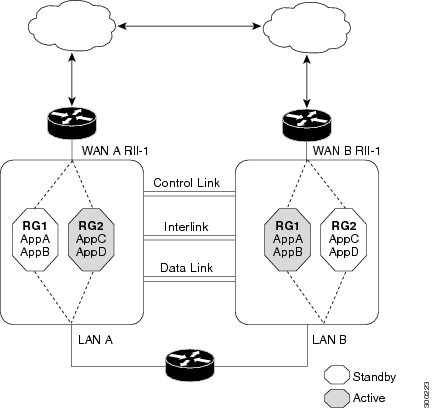
Interchassis Asymmetric Routing Support for Zone-Based Firewall and NAT

The Interchassis Asymmetric Routing Support for Zone-Based Firewall and NAT feature supports the forwarding of packets from a standby redundancy group to the active redundancy group for packet handling. If this feature is not enabled, the return TCP packets forwarded to the router that did not receive the initial synchronization (SYN) message are dropped because they do not belong to any known existing session.

This module provides an overview of asymmetric routing and describes how to configure asymmetric routing

Finding Feature Information

Your software release may not support all the features documented in this module. For the latest caveats and feature information, see Bug Search Tool and the release notes for your platform and software release. To find information about the features documented in this module, and to see a list of the releases in which each feature is supported, see the feature information table.

Use Cisco Feature Navigator to find information about platform support and Cisco software image support. To access Cisco Feature Navigator, go to www.cisco.com/go/cfn. An account on Cisco.com is not required.

Restrictions for Interchassis Asymmetric Routing Support for Zone-Based Firewall and NAT

The following restrictions apply to the Interchassis Asymmetric Routing Support feature:
  • LANs that use virtual IP addresses and virtual MAC (VMAC) addresses do not support asymmetric routing.
  • In Service Software Upgrade (ISSU) is not supported.
The following features are not supported by the VRF-Aware Asymmetric Routing Support feature:
  • Cisco Trustsec
  • Edge switching services
  • Header compression
  • IPsec
  • Policy Based Routing (PBR)
  • Port bundle
  • Lawful intercept
  • Layer 2 Tunneling Protocol (L2TP)
  • Locator/ID Separation Protocol (LISP) inner packet inspection
  • Secure Shell (SSL) VPN
  • Session Border Controller (SBC)
  • If you enable NAT on the primary and backup WAN link, switchover between the primary and backup interface is not supported. NAT backup interface overload is not supported on the following platforms:
    • ASR1000 Series Aggregation Services Routers

    • ISR4000 Series Integrated Services Routers

    • ISR1000 Series Integrated Services Routers

    • CSR1000 Series Cloud Services Routers

Information About Interchassis Asymmetric Routing Support for Zone-Based Firewall and NAT

Asymmetric Routing Overview

Asymmetric routing occurs when packets from TCP or UDP connections flow in different directions through different routes. In asymmetric routing, packets that belong to a single TCP or UDP connection are forwarded through one interface in a redundancy group (RG), but returned through another interface in the same RG. In asymmetric routing, the packet flow remains in the same RG. When you configure asymmetric routing, packets received on the standby RG are redirected to the active RG for processing. If asymmetric routing is not configured, the packets received on the standby RG may be dropped.

Asymmetric routing determines the RG for a particular traffic flow. The state of the RG is critical in determining the handling of packets. If an RG is active, normal packet processing is performed. In case the RG is in a standby state and you have configured asymmetric routing and the asymmetric-routing always-divert enable command, packets are diverted to the active RG. Use the asymmetric-routing always-divert enable command to always divert packets received from the standby RG to the active RG.

The figure below shows an asymmetric routing scenario with a separate asymmetric-routing interlink interface to divert packets to the active RG.

Figure 1. Asymmetric Routing Scenario

The following rules apply to asymmetric routing:

  • 1:1 mapping exists between the redundancy interface identifier (RII) and the interface.

  • 1:n mapping exists between the interface and an RG. (An asymmetric routing interface can receive traffic from and send traffic to multiple RGs. For a non asymmetric-routing interface (normal LAN interface), a 1:1 mapping exists between the interface and the RG.)

  • 1:n mapping exists between an RG and applications that use it. (Multiple applications can use the same RG).

  • 1:1 mapping exists between an RG and the traffic flow. The traffic flow must map only to a single RG. If a traffic flow maps to multiple RGs, an error occurs.

  • 1:1 or 1:n mapping can exist between an RG and an asymmetric-routing interlink as long as the interlink has sufficient bandwidth to support all the RG interlink traffic.

Asymmetric routing consists of an interlink interface that handles all traffic that is to be diverted. The bandwidth of the asymmetric-routing interlink interface must be large enough to handle all expected traffic that is to be diverted. An IPv4 address must be configured on the asymmetric-routing interlink interface, and the IP address of the asymmetric routing interface must be reachable from this interface.


Note

We recommend that the asymmetric-routing interlink interface be used for interlink traffic only and not be shared with high availability control or data interfaces because the amount of traffic on the asymmetric-routing interlink interface could be quite high.


Asymmetric Routing Support in Firewalls

For intrabox asymmetric routing support, the firewall does a stateful Layer 3 and Layer 4 inspection of Internet Control Message Protocol (ICMP), TCP, and UDP packets. The firewall does a stateful inspection of TCP packets by verifying the window size and order of packets. The firewall also requires the state information from both directions of the traffic for stateful inspection. The firewall does a limited inspection of ICMP information flows. It verifies the sequence number associated with the ICMP echo request and response. The firewall does not synchronize any packet flows to the standby redundancy group (RG) until a session is established for that packet. An established session is a three-way handshake for TCP, the second packet for UDP, and informational messages for ICMP. All ICMP flows are sent to the active RG.

The firewall does a stateless verification of policies for packets that do not belong to the ICMP, TCP, and UDP protocols.

The firewall depends on bidirectional traffic to determine when a packet flow should be aged out and diverts all inspected packet flows to the active RG. Packet flows that have a pass policy and that include the same zone with no policy or a drop policy are not diverted.


Note

The firewall does not support the asymmetric-routing always-divert enable command that diverts packets received on the standby RG to the active RG. By default, the firewall forces all packet flows to be diverted to the active RG.


Asymmetric Routing in NAT

By default, when asymmetric routing is configured, Network Address Translation (NAT) processes non-ALG packets on the standby RG, instead of forwarding them to the active. The NAT-only configuration (that is when the firewall is not configured) can use both the active and standby RGs for processing packets. If you have a NAT-only configuration and you have configured asymmetric routing, the default asymmetric routing rule is that NAT will selectively process packets on the standby RG. You can configure the asymmetric-routing always-divert enable command to divert packets received on the standby RG to the active RG. Alternatively, if you have configured the firewall along with NAT, the default asymmetric routing rule is to always divert the packets to the active RG.

When NAT receives a packet on the standby RG and if you have not configured the diverting of packets, NAT does a lookup to see if a session exists for that packet. If a session exists and there is no ALG associated for that session, NAT processes the packet on the standby RG. The processing of packets on the standby RG when a session exists significantly increases the bandwidth of the NAT traffic.

ALGs are used by NAT to identify and translate payload and to create child flows. ALGs require a two-way traffic to function correctly. NAT must divert all traffic to the active RG for any packet flow that is associated with an ALG. This is accomplished by checking if ALG data that is associated with the session is found on the standby RG. If ALG data exits, the packet is diverted for asymmetric routing.

VRF-Aware Software Infrastructure (VASI) support was added in Cisco IOS XE Release 3.16S. Multiprotocol Label Switching (MPLS) asymmetric routing is also supported.

In Cisco IOS XE Release 3.16S, NAT supports asymmetric routing with ALGs, Carrier Grade NAT (CGN), and virtual routing and forwarding (VRF) instances. No configuration changes are required to enable asymmetric routing with ALGs, CGN, or VRF. For more information, see the section, “Example: Configuring Asymmetric Routing with VRF”.

Asymmetric Routing in a WAN-LAN Topology

Asymmetric routing supports only a WAN-LAN topology. In a WAN-LAN topology, devices are connected through LAN interfaces on the inside and WAN interfaces on the outside. There is no control on the routing of return traffic received through WAN links. Asymmetric routing controls the routing of return traffic received through WAN links in a WAN-LAN topology. The figure below shows a WAN-LAN topology.
Figure 2. Asymmetric Routing in a WAN-LAN Topology

VRF-Aware Asymmetric Routing in Zone-Based Firewalls

In Cisco IOS XE Release 3.14S, zone-based firewalls support the VRF-Aware Interchassis Asymmetric Routing feature. The feature supports Multiprotocol Label Switching (MPLS).

During asymmetric routing diversion, the VPN routing and forwarding (VRF) name hash value is sent with diverted packets. The VRF name hash value is converted to the local VRF ID and table ID at the active device after the diversion.

When diverted packets reach the active device on which Network Address Translation (NAT) and the zone-based firewall are configured, the firewall retrieves the VRF ID from NAT or NAT64 and saves the VRF ID in the firewall session key.

The following section describes the asymmetric routing packet flow when only the zone-based firewall is configured on a device:
  • When MPLS is configured on a device, the VRF ID handling for diverted packets is the same as the handling of non-asymmetric routing diverted packets. An MPLS packet is diverted to the active device, even though the MPLS label is removed at the standby device. The zone-based firewall inspects the packet at the egress interface, and the egress VRF ID is set to zero, if MPLS is detected at this interface. The firewall sets the ingress VRF ID to zero if MPLS is configured at the ingress interface.

  • When a Multiprotocol Label Switching (MPLS) packet is diverted to the active device from the standby device, the MPLS label is removed before the asymmetric routing diversion happens.

  • When MPLS is not configured on a device, an IP packet is diverted to the active device and the VRF ID is set. The firewall gets the local VRF ID, when it inspects the packet at the egress interface.

VRF mapping between active and standby devices require no configuration changes.

VRF-Aware Asymmetric Routing in NAT

In Cisco IOS XE Release 3.14S, Network Address Translation supports VRF-aware interchassis asymmetric routing. VRF-aware interchassis asymmetric routing uses message digest (MD) 5 hash of the VPN routing and forwarding (VRF) name to identify the VRF and datapath in the active and standby devices to retrieve the local VRF ID from the VRF name hash and viceversa.

For VRF-aware interchassis asymmetric routing, the VRFs on active and standby devices must have the same VRF name. However, the VRF ID need not be identical on both devices because the VRF ID is mapped based on the VRF name on the standby and active devices during asymmetric routing diversion or box-to-box high availability synchronization.

In case of MD5 hash collision for VRF names, the firewall and NAT sessions that belong to the VRF are not synced to the standby device.

VRF mapping between active and standby devices require no configuration changes.

How to Configure Interchassis Asymmetric Routing Support for Zone-Based Firewall and NAT

Configuring a Redundancy Application Group and a Redundancy Group Protocol

Redundancy groups consist of the following configuration elements:
  • The amount by which the priority will be decremented for each object.

  • Faults (objects) that decrement the priority

  • Failover priority

  • Failover threshold

  • Group instance

  • Group name

  • Initialization delay timer

SUMMARY STEPS

  1. enable
  2. configure terminal
  3. redundancy
  4. application redundancy
  5. group id
  6. name group-name
  7. priority value [failover threshold value]
  8. preempt
  9. track object-number decrement number
  10. exit
  11. protocol id
  12. timers hellotime {seconds | msec msec} holdtime {seconds | msec msec}
  13. authentication {text string | md5 key-string [0 | 7 ] key [timeout seconds] | key-chain key-chain-name}
  14. bfd
  15. end

DETAILED STEPS

  Command or Action Purpose
Step 1

enable

Example:

Device> enable
Enables privileged EXEC mode.
  • Enter your password if prompted

Step 2

configure terminal

Example:

Device# configure terminal

Enters global configuration mode.

Step 3

redundancy

Example:

Device(config)# redundancy

Enters redundancy configuration mode.

Step 4

application redundancy

Example:

Device(config-red)# application redundancy

Configures application redundancy and enters redundancy application configuration mode.

Step 5

group id

Example:

Device(config-red-app)# group 1

Configures a redundancy group and enters redundancy application group configuration mode.

Step 6

name group-name

Example:

Device(config-red-app-grp)# name group1          

Specifies an optional alias for the protocol instance.

Step 7

priority value [failover threshold value]

Example:

Device(config-red-app-grp)# priority 100 failover threshold 50          

Specifies the initial priority and failover threshold for a redundancy group.

Step 8

preempt

Example:

Device(config-red-app-grp)# preempt          
Enables preemption on the redundancy group and enables the standby device to preempt the active device.
  • The standby device preempts only when its priority is higher than that of the active device.

Step 9

track object-number decrement number

Example:

Device(config-red-app-grp)# track 50 decrement 50          

Specifies the priority value of a redundancy group that will be decremented if an event occurs on the tracked object.

Step 10

exit

Example:

Device(config-red-app-grp)# exit          

Exits redundancy application group configuration mode and enters redundancy application configuration mode.

Step 11

protocol id

Example:

Device(config-red-app)# protocol 1          

Specifies the protocol instance that will be attached to a control interface and enters redundancy application protocol configuration mode.

Step 12

timers hellotime {seconds | msec msec} holdtime {seconds | msec msec}

Example:

Device(config-red-app-prtcl)# timers hellotime 3 holdtime 10           
Specifies the interval between hello messages sent and the time period before which a device is declared to be down.
  • Holdtime should be at least three times the hellotime.

Step 13

authentication {text string | md5 key-string [0 | 7 ] key [timeout seconds] | key-chain key-chain-name}

Example:

Device(config-red-app-prtcl)# authentication md5 key-string 0 n1 timeout 100          

Specifies authentication information.

Step 14

bfd

Example:

Device(config-red-app-prtcl)# bfd          
Enables the integration of the failover protocol running on the control interface with the Bidirectional Forwarding Detection (BFD) protocol to achieve failure detection in milliseconds.
  • BFD is enabled by default.

Step 15

end

Example:

Device(config-red-app-prtcl)# end          

Exits redundancy application protocol configuration mode and enters privileged EXEC mode.

Configuring Data, Control, and Asymmetric Routing Interfaces

In this task, you configure the following redundancy group (RG) elements:
  • The interface that is used as the control interface.

  • The interface that is used as the data interface.

  • The interface that is used for asymmetric routing. This is an optional task. Perform this task only if you are configuring asymmetric routing for Network Address Translation (NAT).


Note

Asymmetric routing, data, and control must be configured on separate interfaces for zone-based firewall. However, for Network Address Translation (NAT), asymmetric routing, data, and control can be configured on the same interface.


SUMMARY STEPS

  1. enable
  2. configure terminal
  3. redundancy
  4. application redundancy
  5. group id
  6. data interface-type interface-number
  7. control interface-type interface-number protocol id
  8. timers delay seconds [reload seconds]
  9. asymmetric-routing interface type number
  10. asymmetric-routing always-divert enable
  11. end

DETAILED STEPS

  Command or Action Purpose
Step 1

enable

Example:

Device> enable 
Enables privileged EXEC mode.
  • Enter your password if prompted.

Step 2

configure terminal

Example:

Device# configure terminal 

Enters global configuration mode.

Step 3

redundancy

Example:

Device(config)# redundancy 

Enters redundancy configuration mode.

Step 4

application redundancy

Example:

Device(config-red)# application redundancy 

Configures application redundancy and enters redundancy application configuration mode.

Step 5

group id

Example:

Device(config-red-app)# group 1 

Configures a redundancy group (RG) and enters redundancy application group configuration mode.

Step 6

data interface-type interface-number

Example:

Device(config-red-app-grp)# data GigabitEthernet 0/0/1 

Specifies the data interface that is used by the RG.

Step 7

control interface-type interface-number protocol id

Example:

Device(config-red-app-grp)# control GigabitEthernet 1/0/0 protocol 1 
Specifies the control interface that is used by the RG.
  • The control interface is also associated with an instance of the control interface protocol.

Step 8

timers delay seconds [reload seconds]

Example:

Device(config-red-app-grp)# timers delay 100 reload 400 

Specifies the time required for an RG to delay role negotiations that start after a fault occurs or the system is reloaded.

Step 9

asymmetric-routing interface type number

Example:

Device(config-red-app-grp)# asymmetric-routing interface GigabitEthernet 0/1/1 

Specifies the asymmetric routing interface that is used by the RG.

Step 10

asymmetric-routing always-divert enable

Example:

Device(config-red-app-grp)# asymmetric-routing always-divert enable 

Always diverts packets received from the standby RG to the active RG.

Step 11

end

Example:

Device(config-red-app-grp)# end 

Exits redundancy application group configuration mode and enters privileged EXEC mode.

Configuring a Redundant Interface Identifier and Asymmetric Routing on an Interface


Note

  • You must not configure a redundant interface identifier (RII) on an interface that is configured either as a data interface or as a control interface.
  • You must configure the RII and asymmetric routing on both active and standby devices.
  • You cannot enable asymmetric routing on the interface that has a virtual IP address configured.

SUMMARY STEPS

  1. enable
  2. configure terminal
  3. interface type number
  4. redundancy rii id
  5. redundancy group id [decrement number]
  6. redundancy asymmetric-routing enable
  7. end

DETAILED STEPS

  Command or Action Purpose
Step 1

enable

Example:

Device> enable
Enables privileged EXEC mode.
  • Enter your password if prompted.

Step 2

configure terminal

Example:

Device# configure terminal

Enters global configuration mode.

Step 3

interface type number

Example:

Device(config)# interface GigabitEthernet 0/1/3

Selects an interface to be associated with the redundancy group (RG) and enters interface configuration mode.

Step 4

redundancy rii id

Example:

Device(config-if)# redundancy rii 600

Configures the redundancy interface identifier (RII).

Step 5

redundancy group id [decrement number]

Example:

Device(config-if)# redundancy group 1 decrement 20

Enables the RG redundancy traffic interface configuration and specifies the amount to be decremented from the priority when the interface goes down.

Note 

You need not configure an RG on the traffic interface on which asymmetric routing is enabled.

Step 6

redundancy asymmetric-routing enable

Example:

Device(config-if)# redundancy asymmetric-routing enable

Establishes an asymmetric flow diversion tunnel for each RG.

Step 7

end

Example:

Device(config-if)# end

Exits interface configuration mode and enters privileged EXEC mode.

Configuring Dynamic Inside Source Translation with Asymmetric Routing

The following configuration is a sample dynamic inside source translation with asymmetric routing. You can configure asymmetric routing with the following types of NAT configurations—dynamic outside source, static inside and outside source, and Port Address Translation (PAT) inside and outside source translations. For more information on different types of NAT configurations, see the “Configuring NAT for IP Address Conservation” chapter.

SUMMARY STEPS

  1. enable
  2. configure terminal
  3. interface type number
  4. ip address ip-address mask
  5. ip nat outside
  6. exit
  7. redundancy
  8. application redundancy
  9. group id
  10. asymmetric-routing always-divert enable
  11. end
  12. configure terminal
  13. ip nat pool name start-ip end-ip {mask | prefix-length prefix-length}
  14. exit
  15. ip nat inside source list acl-number pool name redundancy redundancy-id mapping-id map-id
  16. access-list standard-acl-number permit source-address wildcard-bits
  17. end

DETAILED STEPS

  Command or Action Purpose
Step 1

enable

Example:

Device> enable
Enables privileged EXEC mode.
  • Enter your password if prompted.

Step 2

configure terminal

Example:

Device# configure terminal

Enters global configuration mode.

Step 3

interface type number

Example:

Device(config)# interface gigabitethernet 0/1/3

Configures an interface and enters interface configuration mode.

Step 4

ip address ip-address mask

Example:

Device(config-if)# ip address 10.1.1.1 255.255.255.0

Sets a primary IP address for an interface.

Step 5

ip nat outside

Example:

Device(config-if)# ip nat outside

Marks the interface as connected to the outside.

Step 6

exit

Example:

Device(config-if)# exit

Exits interface configuration mode and enters global configuration mode.

Step 7

redundancy

Example:

Device(config)# redundancy

Configures redundancy and enters redundancy configuration mode.

Step 8

application redundancy

Example:

Device(config-red)# application redundancy

Configures application redundancy and enters redundancy application configuration mode.

Step 9

group id

Example:

Device(config-red-app)# group 1

Configures a redundancy group and enters redundancy application group configuration mode.

Step 10

asymmetric-routing always-divert enable

Example:

Device(config-red-app-grp)# asymmetric-routing always-divert enable

Diverts the traffic to the active device.

Step 11

end

Example:

Device(config-red-app-grp)# end

Exits redundancy application group configuration mode and enters privileged EXEC mode.

Step 12

configure terminal

Example:

Device# configure terminal

Enters global configuration mode.

Step 13

ip nat pool name start-ip end-ip {mask | prefix-length prefix-length}

Example:

Device(config)# ip nat pool pool1 prefix-length 24 
Defines a pool of global addresses.
  • Enters IP NAT pool configuration mode.

Step 14

exit

Example:

Device(config-ipnat-pool)# exit

Exits IP NAT pool configuration mode and enters global configuration mode.

Step 15

ip nat inside source list acl-number pool name redundancy redundancy-id mapping-id map-id

Example:

Device(config)# ip nat inside source list pool pool1 redundancy 1 mapping-id 100

Enables NAT of the inside source address and associates NAT with a redundancy group by using the mapping ID.

Step 16

access-list standard-acl-number permit source-address wildcard-bits

Example:

Device(config)# access-list 10 permit 10.1.1.1 255.255.255.0

Defines a standard access list for the inside addresses that are to be translated.

Step 17

end

Example:

Device(config)# end

Exits global configuration mode and enters privileged EXEC mode.

Configuration Examples for Interchassis Asymmetric Routing Support for Zone-Based Firewall and NAT

Example: Configuring a Redundancy Application Group and a Redundancy Group Protocol

Device# configure terminal	
Device(config)# redundancy
Device(config-red)# application redundancy
Device(config-red-app)# group 1
Device(config-red-app-grp)# name group1
Device(config-red-app-grp)# priority 100 failover threshold 50
Device(config-red-app-grp)# preempt
Device(config-red-app-grp)# track 50 decrement 50
Device(config-red-app-grp)# exit
Device(config-red-app)# protocol 1
Device(config-red-app-prtcl)# timers hellotime 3 holdtime 10
Device(config-red-app-prtcl)# authentication md5 key-string 0 n1 timeout 100
Device(config-red-app-prtcl)# bfd
Device(config-red-app-prtcl)# end

Example: Configuring Data, Control, and Asymmetric Routing Interfaces

Device# configure terminal
Device(config)# redundancy 
Device(config-red)# application redundancy
Device(config-red-app)# group 1
Device(config-red-app-grp)# data GigabitEthernet 0/0/1
Device(config-red-app-grp)# control GigabitEthernet 1/0/0 protocol 1
Device(config-red-app-grp)# timers delay 100 reload 400 
Device(config-red-app-grp)# asymmetric-routing interface GigabitEthernet 0/1/1 
Device(config-red-app-grp)# asymmetric-routing always-divert enable
Device(config-red-app-grp)# end 

Example: Configuring a Redundant Interface Identifier and Asymmetric Routing on an Interface

Device# configure terminal
Device(config)# interface GigabitEthernet 0/1/3
Device(config-if)# redundancy rii 600
Device(config-if)# redundancy group 1 decrement 20
Device(config-if)# redundancy asymmetric-routing enable 
Device(config-if)# end

Example: Configuring Dynamic Inside Source Translation with Asymmetric Routing

Device(config)# interface gigabitethernet 0/1/3
Device(config-if)# ip address 10.1.1.1 255.255.255.0
Device(config-if)# ip nat outside
Device(config-if)# exit
Device(config)# redundancy
Device(config-red)# application redundancy
Device(config-red-app)# group 1
Device(config-red-app-grp)# asymmetric-routing always-divert enable
Device(config-red-app-grp)# end
Device# configure terminal
Device(config)# ip nat pool pool1 prefix-length 24
Device(config-ipnat-pool)# exit
Device(config)# ip nat inside source list pool pool1 redundancy 1 mapping-id 100
Device(config)# access-list 10 permit 10.1.1.1 255.255.255.0

Example: Configuring VRF-Aware NAT for WAN-WAN Topology with Symmetric Routing Box-to-Box Redundancy

The following is a sample WAN-to-WAN symmetric routing configuration:


vrf definition Mgmt-intf 
 address-family ipv4 
  exit-address-family
!  
address-family ipv6 
 exit-address-family
!
!
vrf definition VRFA 
 rd 100:1 
 route-target export 100:1 
 route-target import 100:1 
 address-family ipv4 
  exit-address-family
!
!
no logging console
no aaa new-model
!
multilink bundle-name authenticated
!
redundancy 
 mode sso 
 application redundancy  
  group 1   
   preempt   
   priority 120   
   control GigabitEthernet 0/0/1 protocol 1   
   data GigabitEthernet 0/0/2
!
!
!
!
ip tftp source-interface GigabitEthernet0
ip tftp blocksize 8192
!
track 1 interface GigabitEthernet 0/0/4 line-protocol
!
interface Loopback 0 
 ip address 209.165.201.1 255.255.255.224
!
interface GigabitEthernet 0/0/0 
 vrf forwarding VRFA 
 ip address 192.168.0.1 255.255.255.248 
 ip nat inside 
 negotiation auto 
 bfd interval 50 min_rx 50 multiplier 3 
 redundancy rii 2
!
interface GigabitEthernet 0/0/1 
 ip address 209.165.202.129 255.255.255.224 
 negotiation auto
!
interface GigabitEthernet 0/0/2 
 ip address 192.0.2.1 255.255.255.224 
 negotiation auto
!
interface GigabitEthernet 0/0/3 
 ip address 198.51.100.1 255.255.255.240 
 negotiation auto
!
interface GigabitEthernet 0/0/4 
 ip address 203.0.113.1 255.255.255.240 
 negotiation auto
!
interface GigabitEthernet 0 
 vrf forwarding Mgmt-intf 
 ip address 172.16.0.1 255.255.0.0 
 negotiation auto
!
interface vasileft 1 
 vrf forwarding VRFA 
 ip address 10.4.4.1 255.255.0.0 
 ip nat outside 
 no keepalive
!
interface vasiright 1 
ip address 10.4.4.2 255.255.0.0 
no keepalive
!
router mobile
!
router bgp 577 
 bgp router-id 1.1.1.1 
 bgp log-neighbor-changes 
 neighbor 203.0.113.1 remote-as 223 
 neighbor 203.0.113.1 description PEERING to PTNR neighbor 10.4.4.1 remote-as 577 
 neighbor 10.4.4.1 description PEEERING to VASI VRFA interface 
!
address-family ipv4  
 network 203.0.113.1 mask 255.255.255.240  
 network 10.4.0.0 mask 255.255.0.0  
 network 209.165.200.224 mask 255.255.255.224  
 neighbor 203.0.113.1 activate  
 neighbor 10.4.4.1 activate  
 neighbor 10.4.4.1 next-hop-self 
 exit-address-family 
!
address-family ipv4 vrf VRFA  
 bgp router-id 4.4.4.4  
 network 192.168.0.0 mask 255.255.255.248  
 network 10.4.0.0 mask 255.255.0.0  
 redistribute connected  
 redistribute static  
 neighbor 192.168.0.2 remote-as 65004  
 neighbor 192.168.0.2 fall-over bfd  
 neighbor 192.168.0.2 activate  
 neighbor 10.4.4.2 remote-as 577  
 neighbor 10.4.4.2 description PEERING to VASI Global intf  
 neighbor 10.4.4.2 activate 
 exit-address-family
!
ip nat switchover replication http
ip nat pool att_pool 209.165.200.225 209.165.200.225 prefix-length 16
ip nat inside source list 4 pool att_pool redundancy 1 mapping-id 100 vrf VRFA overload
ip forward-protocol nd
!
no ip http server
no ip http secure-server
ip route 203.0.113.1 255.255.255.224 10.4.4.1
ip route 192.168.0.0 255.255.0.0 10.4.4.1
ip route 209.165.200.224 255.255.255.224 10.4.4.1
ip route vrf Mgmt-intf 209.165.200.1 255.255.255.224 172.16.0.0
!
ip prefix-list VRF_Pool seq 5 permit 209.165.200.0/27
ip prefix-list p1-adv-1 seq 5 permit 209.165.200.0/27
ip prefix-list p1-exist-1 seq 5 permit 203.0.113.193/27
logging esm config
access-list 4 permit 203.0.113.193 255.255.255.224
!
control-plane
line console 0 
 stopbits 1
!
line vty 0 3 
 login
!
line vty 4 
 password lab 
 login
!
end

Example: Configuring Asymmetric Routing with VRF

The following example shows how to configure asymmetric routing with virtual routing and forwarding (VRF) instances:

Device(config)# redundancy
Device(config-red)# mode sso
Device(config-red)# application redundancy
Device(config-red-app)# group 1
Device(config-red-app-grp)# name RG1
Device(config-red-app-grp)# preempt
Device(config-red-app-grp)# priority 100 failover threshold 40
Device(config-red-app-grp)# control GigabitEthernet 1/0/3 protocol 1
Device(config-red-app-grp)# data GigabitEthernet 1/0/3
Device(config-red-app-grp)# asymmetric-routing interface GigabitEthernet 1/0/4
Device(config-red-app-grp)# asymmetric-routing always-divert enable
Device(config-red-app-grp)# exit
Device(config-red-app)# exit
Device(config-red)# exit
!
Device(config)# interface TenGigabitEthernet 2/0/0
Device(config-if)# ip vrf forwarding vrf001
Device(config-if)# ip address 10.0.0.1 255.255.255.0
Device(config-if)# ip nat inside
Device(config-if)# exit
!
Device(config)# interface TenGigabitEthernet 3/0/0
Device(config-if)# ip vrf forwarding vrf001
Device(config-if)# ip address 192.0.2.1 255.255.255.0
Device(config-if)# ip nat outside
Device(config-if)# exit
!
Device(config-if)# ip nat pool pool-vrf001 209.165.201.1 209.165.201.30 prefix-length 24
Device(config-if)# ip nat inside source list 1 pool pool-vrf001 redundancy 1 mapping-id 1 vrf vrf001 match-in-vrf overload
Device(config-if)# end


Additional References for Interchassis Asymmetric Routing Support for Zone-Based Firewall and NAT

Related Documents

Related Topic

Document Title

Cisco IOS commands

Cisco IOS Master Command List, All Releases

Security commands

Firewall inter-chassis redundancy

“Configuring Firewall Stateful Inter-Chassis Redundancy” module

NAT inter-chassis redundancy

“Configuring Stateful Inter-Chassis Redundancy” module

Technical Assistance

Description

Link

The Cisco Support and Documentation website provides online resources to download documentation, software, and tools. Use these resources to install and configure the software and to troubleshoot and resolve technical issues with Cisco products and technologies. Access to most tools on the Cisco Support and Documentation website requires a Cisco.com user ID and password.

http://www.cisco.com/cisco/web/support/index.html

Feature Information for Interchassis Asymmetric Routing Support for Zone-Based Firewall and NAT

Table 1. Feature Information for Interchassis Asymmetric Routing Support for Zone-Based Firewall and NAT

Feature Name

Releases

Feature Information

Asymmetric Routing Enhancements for NAT44

Cisco IOS XE Release 3.16S

The Asymmetric Routing Enhancements for NAT44 feature supports asymmetric routing with CGN, ALGs, VRF, VASI and MPLS.

No commands were introduced or modified.

Interchassis Asymmetric Routing Support for Zone-Based Firewall and NAT

Cisco IOS XE Release 3.5S

The Interchassis Asymmetric Routing Support for Zone-Based Firewall and NAT feature supports the forwarding of packets from a standby redundancy group to the active redundancy group for packet handling.

The following commands were introduced or modified: asymmetric-routing , redundancy asymmetric-routing enable .

VRF-Aware Interchassis Asymmetric Routing Support for Zone-Based Firewalls

Cisco IOS XE Release 3.14S

Zone-based firewalls support the VRF-Aware Interchassis Asymmetric Routing feature. This feature supports MPLS. There are no configuration changes for this feature.

No commands were introduced or modified.

VRF-Aware Interchassis Asymmetric Routing Support for NAT

Cisco IOS XE Release 3.14S

NAT supports the VRF-Aware Interchassis Asymmetric Routing feature. This feature supports MPLS. There are no configuration changes for this feature.

No commands were introduced or modified.