EVPN Configuration Guide for Cisco 8000 Series Routers, IOS XR Release 24.1.x, 24.2.x, 24.3.x, 24.4.x
Bias-Free Language
The documentation set for this product strives to use bias-free language. For the purposes of this documentation set, bias-free is defined as language that does not imply discrimination based on age, disability, gender, racial identity, ethnic identity, sexual orientation, socioeconomic status, and intersectionality. Exceptions may be present in the documentation due to language that is hardcoded in the user interfaces of the product software, language used based on RFP documentation, or language that is used by a referenced third-party product. Learn more about how Cisco is using Inclusive Language.
This chapter describes how to configure EVPN MPLS Single Homing.
EVPN E-LAN L2 Gateway Single-Homing
Table 1. Feature History Table
Feature Name
Release Information
Feature Description
EVPN E-LAN L2 Gateway Single-Homing
Release 24.4.1
Introduced in this release on: Fixed Systems (8700) (select variants only*)
* The EVPN single-homing functionality is now extended to the Cisco 8712-MOD-M routers.
EVPN E-LAN L2 Gateway Single-Homing
Release 24.3.1
Introduced in this release on: Fixed Systems (8200, 8700); Modular Systems (8800 [LC ASIC: P100]) (select variants only*)
* The EVPN single-homing functionality is now extended to these fixed systems and line cards.
8212-48FH-M
8711-32FH-M
88-LC1-52Y8H-EM
88-LC1-12TH24FH-E
EVPN E-LAN L2 Gateway Single-Homing
Release 24.2.11
Introduced in this release on: Modular Systems (8800 [LC ASIC: P100]) (select variants only*)
* The EVPN single-homing functionality is now extended to the Cisco 88-LC1-36EH routers.
EVPN E-LAN L2 Gateway Single-Homing
Release 7.11.1
We now offer a cost-effective and simplified solution for seamless communication between various customer sites connected
to the same service provider network using Ethernet Virtual Private Network (EVPN) single-homing mode. EVPN LAN (E-LAN) is
a service to bridge Ethernet data traffic among different sites across the MPLS network connecting a Layer 2 gateway device
to a single access network.
In the single-homing mode, a device is connected to one router in the MPLS core through physical ports or bundle ports, and
in the event of a failure on those links, the traffic over the links is not protected by links to another router on the core.
This feature is supported only on Q200-based line cards.
Deploying EVPN single-homing can simplify network infrastructure management and scaling
by requiring only one provider edge router for connectivity, resulting in significant
benefits. Additionally, reducing the need for additional infrastructure through
implementing EVPN single-homing can lead to substantial cost savings for the initial
setup and ongoing maintenance.
The EVPN network provides a solution for linking a network or device to a single physical
or bundle link. This approach does not come with built-in redundancy or automatic
failover capabilities. Nevertheless, you can use various mechanisms to ensure high
availability and minimize downtime through appropriate failover mechanisms like link or
route redundancy. Evaluating your specific network requirements is essential when
deploying EVPN single-homing. Although this option offers cost savings and simplicity,
it may be better suited to smaller or medium-sized enterprises that require only a
single connection to the EVPN network.
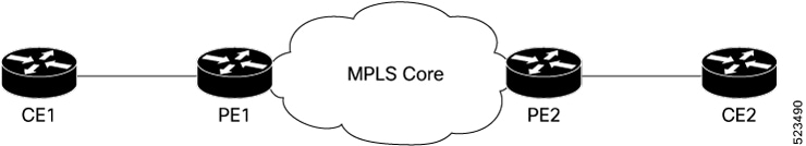
Topology
Using this topology, let’s understand how EVPN E-LAN Layer 2 gateway single-homing
transports traffic from one customer site to another.
CE1 is connected to PE1 using a single bundle or physical link. When you send
Layer 2 traffic from CE1 to CE2, the traffic is encapsulated in Layer 2
frames.
PE1 receives the Layer 2 frames on the ingress interface from CE1. PE1 checks
the destination MAC address of the frame and determines the appropriate
attachment circuit to forward the frame.
PE1 then uses EVPN control plane protocols to distribute the MAC address
information learned from CE1 to PE2.
PE2 router that has the destination MAC address obtained from the EVPN
control plane forwards the Layer 2 frames to the appropriate attachment
circuit connected to CE2.
Configure EVPN E-LAN L2 Gateway Single -Homing
In this topology, configure EVPN E-LAN L2 Gateway single-homing on PE1. You must
configure Ethernet VPN Identifier (EVI) under the bridge domain and enable PE1 to
advertise MAC addresses to distribute the MAC address information learned from CE1 to
PE2.
Perform the following tasks to configure EVPN E-LAN L2 gateway single-homing on PE1:
Disable EVPN multi-homing onbundle interface.
Set up BGP for L2VPN and EVPN
Configure bridge domain
Configure MAC advertisement
Configuration Example
/* Set up BGP for L2VPN and EVPN */
Router# configure
Router#(config)# router bgp 200
Router#(config-bgp)# bgp router-id 10.10.10.1
Router#(config-bgp)# address-family l2vpn evpn
Router#(config-bgp)# neighbor 10.10.10.10
Router#(config-bgp-nbr)# remote-as 200
Router#(config-bgp-nbr)# update-source Loopback 0
Router#(config-bgp-nbr)# address-family l2vpn evpn

/* Configure bridge domain */
Router(config)# l2vpn
Router (config-l2vpn)# bridge group BG1
Router (config-l2vpn-bg)# bridge-domain BD1
Router (config-l2vpn-bg-bd)# interface Bundle-Ether1.2001
Router (config-l2vpn-bg-bd-ac)# evi 2001


/* By default, the bundle interface is in EVPN multi-homing mode.
To disable EVPN multi-homing, configure bundle-Ether AC with ESI value (identifier type) set to zero. */
Router(config)# evpn
Router(config-evpn)# interface Bundle-Ether1
Router(config-evpn-ac)# ethernet-segment
Router(config-evpn-ac-es)# identifier type 0 00.00.00.00.00.00.00.00.00

/* As an alternative, you can disable EVPN multi-homing globally */

Router(config)# evpn
Router(config-evpn)# ethernet-segment type 1 auto-generation-disable

/* Configure MAC advertisement. */
Router(config)# evpn
Router(config-evpn)# evi 2001
Router(config-evpn-instance)# advertise-mac
Router(config-evpn-instance-mac)# commit
Running Configuration
This section shows an EVPN E-LAN L2 gateway single-homing running configuration.
Verify that EVPN E-LAN L2 gateway single-homing is configured.
In this example, the operational mode is SH or single-homing, which indicates that
CE1 is connected to PE1 through a single link.
Router# show evpn ethernet-segment interface Bundle-Ether 1 detail

Ethernet Segment Id    Interface        Nexthops
--------------------   ----------       ----------
N/A                    Bundle-Ether 1   10.0.0.2
……………
Topology :
Operational : SH
Seamless Migration of VPLS Network to EVPN Network
Table 2. Feature History Table
Feature Name
Release Information
Feature Description
Seamless Migration of VPLS Network to EVPN Network
Release 24.4.1
Introduced in this release on: Fixed Systems (8700) (select variants only*)
* The seamless VPLS-to-EVPN migration is now extended to the Cisco 8712-MOD-M routers.
Seamless Migration of VPLS Network to EVPN Network
Release 24.3.1
Introduced in this release on: Fixed Systems (8200, 8700); Modular Systems (8800 [LC ASIC: P100]) (select variants only*)
* The seamless VPLS-to-EVPN migration is now extended to:
8212-48FH-M
8711-32FH-M
88-LC1-52Y8H-EM
88-LC1-12TH24FH-E
Seamless Migration of VPLS Network to EVPN Network
Release 24.2.11
Introduced in this release on: Modular Systems (8800 [LC ASIC: P100]) (select variants only*)
* The seamless VPLS-to-EVPN migration is now extended to routers with the 88-LC1-36EH line cards.
Seamless Migration of VPLS Network to EVPN Network
Release 7.11.1
You can now provision EVPN service on existing VPLS-enabled PEs individually, thus ensuring a seamless VPLS-to-EVPN migration
without traffic disruption.
This feature is supported only on Q200-based line cards.
Although VPLS is a widely deployed Layer 2 VPN technology, customers prefer to migrate their
VPLS network to EVPN to leverage the scaling benefits and ease of deployment. Recognizing the
significance of preserving investments in VPLS, certain service providers seek ways to
seamlessly connect their existing VPLS networks with the new networks running EVPN.
You can now migrate the PE nodes from legacy VPLS to EVPN gradually and incrementally without
any service disruption.
Instead of performing a network-wide software upgrade at the same time on all PEs, this
feature provides the flexibility to migrate one PE at a time. Thus allows the coexistence of
legacy VPLS and EVPN-VPLS dual-stack in the core for a given L2 attachment circuit (AC) over
the same MPLS network.
In the EVPN network, VPN instances are grouped by EVPN instance ID (EVI-ID). Similar to other
L2VPN technologies, EVPN instances are also associated with route-targets and
route-distinguisher. EVPN uses a control plane for learning and propagating MAC unlike
traditional VPLS, where MAC is learned in the data plane using flood and learn technique. In
EVPN, MAC routes are carried by the MP-BGP protocol. In EVPN enabled PEs, PEs import the MAC
route along with the label to their respective EVPN forwarding table only if their route
targets (RTs) match. An EVPN PE router is capable of performing VPLS and EVPN L2 bridging in
the same VPN instance. When both EVPN and BGP-AD PW are configured in a VPN instance, the EVPN
PEs advertise the BGP VPLS autodiscovery (AD) route and the BGP EVPN Inclusive Multicast route
(type-3) for a given VPN Instance. Route type-3 referred to as ingress replication multicast
route, is used to send broadcast, unknown unicast, and multicast (BUM) traffic. Other remote
PEs import type-3 routes for the same VPN instance only if the sending PE RTs match with their
configured RT. Thus, at the end of these route-exchanges, EVPN capable PEs discover all other
PEs in the VPN instance and their associated capabilities. The type-3 routes used by PE to
send its BUM traffic to other PEs ensure that PEs with the same RTs receive the BUM traffic.
EVPN advertises the customer MAC address using type-2 route.
Seamless migration allows you to upgrade the VPLS PE routers to EVPN one by one without any
network service disruption. Consider the following topology where PE1, PE2, PE3, and PE4 are
interconnected in a full-meshed network using VPLS PW.
Figure 1. Seamless Migration of VPLS Network to EVPN Network
You can introduce the EVPN service to all the selected VPLS provider edge (PE) nodes
simultaneously. However, to avoid traffic disruption, provision EVPN service on existing
VPLS-enabled PEs one by one.
To migrate from VPLS to EVPN, enable EVPN in a VPN instance of VPLS service on PE1, which
starts advertising the EVPN inclusive multicast route to other PE nodes.
Since no inclusive multicast routes are received from other PE nodes, VPLS pseudowires
between PE1 and other PE nodes remain active.
PE1 forwards traffic using VPLS pseudowires and advertises all MAC addresses learned from
CE1 using EVPN route type-2.
Next, enable EVPN on PE3, and it starts advertising an inclusive multicast route to other
PE nodes.
PE1 and PE3 discover each other through EVPN routes and shut down pseudowires between
them.
EVPN service replaces VPLS service between PE1 and PE3.
PE1 keeps running VPLS service with PE2 and PE4 and starts EVPN service with PE3 in the
same VPN instance called EVPN seamless integration with VPLS.
Migrate the remaining PE nodes until all four PE nodes are enabled with the EVPN
service.
Eventually, the VPLS service is completely replaced with the EVPN service in the network,
and all VPLS pseudowires are shut down.
Configure EVPN on the Existing VPLS Network
Perform the following tasks to configure EVPN on the existing VPLS network.
Configure L2VPN EVPN address-family
Configure EVI and corresponding BGP route-targets under EVPN configuration
mode
Configure EVI under a bridge-domain
Configure L2 EVPN Address-Family
Configure BGP on the PE routers and enable EVPN address family under both BGP and
participating neighbors.
Verify the number of EVI’s configured, local and remote MAC-routes that are advertised.
Router#show evpn summary
-----------------------------
Global Information
-----------------------------
Number of EVIs                     : 6
Number of Local EAD Entries        : 0
Number of Remote EAD Entries       : 0
Number of Local MAC Routes         : 4
          MAC                      : 4
          MAC-IPv4                 : 0
          MAC-IPv6                 : 0
Number of Local ES:Global MAC      : 1
Number of Remote MAC Routes        : 0
          MAC                      : 0
          MAC-IPv4                 : 0
          MAC-IPv6                 : 0
Number of Remote SOO MAC Routes    :0
Number of Local IMCAST Routes      : 4
Number of Remote IMCAST Routes     : 4
Number of Internal Labels          : 0
Number of ES Entries               : 1
Number of Neighbor Entries         : 4
EVPN Router ID                     : 200.0.1.1
BGP ASN                            : 65530
PBB BSA MAC address                : 0026.982b.c1e5
Global peering timer               :      3 seconds
Global recovery timer              :     30 seconds
Verify EVPN MAC routes pertaining to specific VPN instance.
Router#show evpn evi vpn-id 1 mac
Mon Feb 20 21:36:23.574 EST

EVI        MAC address    IP address                   Nexthop                            Label
---------- -------------- ---------------------------------------- ---------------------------------
1      0033.0000.0001      ::                       200.0.1.1                          45106
Configure EVI under a Bridge Domain
Perform this task to configure EVI under the corresponding L2VPN bridge domain.
Router# show l2vpn bridge-domain
Legend: pp = Partially Programmed.
Bridge group: vplstoevpn, bridge-domain: vplstoevpn, id: 0, state: up, ShgId: 0, MSTi: 0
  Aging: 300 s, MAC limit: 4000, Action: none, Notification: syslog
  Filter MAC addresses: 0
  ACs: 1 (1 up), VFIs: 1, PWs: 2 (1 up), PBBs: 0 (0 up), VNIs: 0 (0 up)
  List of EVPNs:
    EVPN, state: up
  List of ACs:
    Hu0/0/0/0, state: up, Static MAC addresses: 0, MSTi: 5
  List of Access PWs:
  List of VFIs:
    VFI vpls (up)
      Neighbor 172.16.0.1 pw-id 12, state: down, Static MAC addresses: 0
      Neighbor 192.168.0.1 pw-id 13, state: up, Static MAC addresses: 0
The output indicates that the VPLS PW "neighbor 172.16.0.1 pw-id 12" is replaced by EVPN
service, as the EVPN control plane discovered that both local PE and remote PE (172.16.0.1)
have enabled EVPN service on the L2VPN instance.
EVPN Virtual Private Wire Service (VPWS) - Ethernet Line (E-Line) Service
The terms Virtual Private Wire Service (VPWS) and Ethernet Line (E-Line) Service are used interchangeably.
Table 3. Feature History Table
Feature Name
Release Information
Feature Description
Ethernet VPN Virtual Private Wire Service
Release 24.4.1
Introduced in this release on: Fixed Systems (8700) (select variants only*)
* The EVPN VPWS or E-Line service is now extended to the Cisco 8712-MOD-M routers.
Ethernet VPN Virtual Private Wire Service
Release 24.3.1
Introduced in this release on: Fixed Systems (8200, 8700); Modular Systems (8800 [LC ASIC: P100]) (select variants only*)
* The EVPN VPWS or E-Line service is now extended to:
8212-48FH-M
8711-32FH-M
88-LC1-52Y8H-EM
88-LC1-12TH24FH-E
Ethernet VPN Virtual Private Wire Service
Release 24.2.11
Introduced in this release on: Modular Systems (8800 [LC ASIC: Q200, P100]) (select variants only*)
* The EVPN VPWS or E-Line service is now extended to routers with the Q200 and 88-LC1-36EH line cards.
Ethernet VPN Virtual Private Wire Service
Release 7.8.1
The Ethernet VPN Virtual Private Wire Service (EVPN-VPWS) is a BGP control plane solution for point-to-point services. It
implements the signaling and encapsulation techniques for establishing an EVPN instance between a pair of PEs. It provides
the service of forwarding L2 Ethernet traffic between network devices without inspecting the MAC header in the Ethernet frame.
The use of EVPN for VPWS eliminates the need for signaling single-segment and multi-segment pseudowire (PW) for point-to-point
Ethernet services.
The EVPN-VPWS (E-Line) technology works on IP and MPLS core; IP core to support BGP and MPLS core for switching packets between
the endpoints.
EVPN-VPWS Single-Homing
The EVPN-VPWS single-homing solution requires per EVI Ethernet Auto Discovery route. EVPN defines a new BGP Network Layer
Reachability Information (NLRI) used to carry all EVPN routes. BGP Capabilities Advertisement used to ensure that two speakers
support EVPN NLRI (AFI 25, SAFI 70) as per RFC 4760.
The architecture for EVPN-VPWS is that the PEs run Multi-Protocol BGP in a control-plane.
The following image describes the EVPN-VPWS configuration:
Figure 2. EVPN-VPWS Single-Homing
The VPWS service on PE1 requires the following three elements to be specified at the configuration time:
The VPN ID (EVI).
The local AC identifier (AC1) that identifies the local end of the emulated service.
The remote AC identifier (AC2) that identifies the remote end of the emulated service.
PE1 allocates an MPLS label per local AC for reachability.
The VPWS service on PE2 is set in the same manner as PE1. The three same elements are required and the service configuration
must be symmetric.
PE2 allocates an MPLS label per local AC for reachability.
PE1 advertises a single EVPN per EVI Ethernet AD route for each local endpoint (AC) to remote PEs with the associated MPLS
label.
PE2 performs the same task.
On reception of EVPN per EVI EAD route from PE2, PE1 adds the entry to its local EVPN data base. PE1 knows the path list to
reach AC2, for example, next hop is PE2 IP address and MPLS label for AC2.
PE2 performs the same task.
Restrictions for EVPN-VPWS
EVPN-VPWS does not support Pseudowire Headend (PWHE) configuration.
Configure EVPN-VPWS
Single Homed
This section describes how to configure single-homed EVPN-VPWS feature.
Introduced in this release on: Fixed Systems (8700) (select variants only*)
The Flow Label support improves traffic distribution by enabling flow-based load balancing between provider edge devices.
It uses Flow-Aware Transport (FAT) pseudowires over an MPLS network to efficiently manage traffic across BGP-signaled pseudowires
in an Ethernet VPN. Flow labels, based on packet flows, help optimize traffic across equal cost multipaths or link-bundled
paths.
* This feature is now supported on the Cisco 8712-MOD-M routers.
The Flow Label support for EVPN E-Line feature enables provider (P) routers to use the flow-based load balancing to forward
traffic between the provider edge (PE) devices. This feature uses Flow-Aware Transport (FAT) of pseudowires (PW) over an MPLS
packet switched network for load-balancing traffic across BGP-based signaled pseudowires for EVPN E-Line.
FAT PWs provide the capability to identify individual flows within a PW and provide routers the ability to use these flows
to load-balance the traffic. FAT PWs are used to load balance the traffic in the core when equal cost multipaths (ECMP) are
used. A flow label is created based on indivisible packet flows entering an imposition PE. This flow label is inserted as
the lower most label in the packet. P routers use the flow label for load balancing to provide better traffic distribution
across ECMP paths or link-bundled paths in the core. A flow is identified either by the source and destination IP address
of the traffic, or the source and destination MAC address of the traffic.
The following figure shows a FAT PW with two flows distributing over ECMPs and bundle links.
Figure 3. FAT PW with Two Flows Distributing over ECMPs and Bundle Links
An extra label is added to the stack, called the flow label, which is generated for each unique incoming flow on the PE. A
flow label is a unique identifier that distinguishes a flow within the PW, and is derived from source and destination MAC
addresses, and source and destination IP addresses. The flow label contains the end of label stack (EOS) bit set. The flow
label is inserted after the VC label and before the control word (if any). The ingress PE calculates and forwards the flow
label. The FAT PW configuration enables the flow label. The egress PE discards the flow label such that no decisions are made.
Core routers perform load balancing using the flow-label in the FAT PW with other information like MAC address and IP address.
The flow-label adds greater entropy to improve traffic load balancing. Therefore, it is possible to distribute flows over
ECMPs and link bundles.
In this topology, the imposition router, PE1, adds a flow label in the traffic. The disposition router, PE2, allows mixed
types of traffic of which some have flow label, others do not. The P router uses flow label to load balance the traffic between
the PEs. PE2 ignores the flow label in traffic, and uses one EVPN label for all unicast traffic.
Restrictions
To configure flow label for EVPN E-Line, the following restrictions are applicable:
This feature is not supported for EVPN Point-to-Multipoint (P2MP) of VPLS and Ethernet LAN (E-LAN) service.
This feature is supported only for EVPN E-Line single homing. AC bundle interfaces must be configured with ESI-0 only.
This feature is not supported for EVPN flexible cross-connect service.
This feature is not supported for EVPN E-Line multihoming.
Configure Flow Label for EVPN E-Line
Configuration Example
Perform this task to configure flow label for EVPN E-Line on both PE1 and PE2.
This section shows the running configuration of flow label for EVPN E-Line.
l2vpn
 xconnect group evpn-vpws
  p2p evpn1
   interface TenGigE0/0/0/0
   neighbor evpn evi 1 target 2 source 1
   !
  !
evpn
 evi 1
   load-balancing
   flow-label static
  !
!
Verification
Verify EVPN E-Line flow label configuration.
Router# show l2vpn xconnect detail
Group evpn-vpws, XC evpn1, state is up; Interworking none
  AC: TenGigE0/0/0/0, state is up
    Type Ethernet
    MTU 1500; XC ID 0x1; interworking none
    Statistics:
      packets: received 21757444, sent 0
      bytes: received 18226521128, sent 0
  EVPN: neighbor 100.100.100.2, PW ID: evi 1, ac-id 2, state is up ( established )
    XC ID 0xc0000001
    Encapsulation MPLS
   Encap type Ethernet, control word disabled
    Sequencing not set
    LSP : Up
    Flow Label flags configured (Tx=1,Rx=1) statically

      EVPN         Local                          Remote
      ------------ ------------------------------ -----------------------------
      Label        64002                          64002
      MTU          1500                           1500
      Control word disabled                       disabled
      AC ID        1                              2
      EVPN type    Ethernet                       Ethernet

      ------------ ------------------------------ -----------------------------
    Create time: 30/10/2018 03:04:16 (00:00:40 ago)
    Last time status changed: 30/10/2018 03:04:16 (00:00:40 ago)
    Statistics:
      packets: received 0, sent 21757444
      bytes: received 0, sent 18226521128
EVPN Seamless Integration with Legacy VPWS
Table 5. Feature History Table
Feature Name
Release Information
Feature Description
EVPN Seamless Integration with Legacy VPWS
Release 24.4.1
Introduced in this release on: Fixed Systems (8700) (select variants only*)
* The seamless migration of VPWS to EVPN-VPWS services functionality is now extended to the Cisco 8712-MOD-M routers.
EVPN Seamless Integration with Legacy VPWS
Release 24.3.1
Introduced in this release on: Modular Systems (8800 [LC ASIC: P100]) (select variants only*)
* The seamless migration of VPWS to EVPN-VPWS services functionality is now extended to these fixed systems and line cards:
8212-48FH-M
8711-32FH-M
88-LC1-52Y8H-EM
88-LC1-12TH24FH-E
EVPN Seamless Integration with Legacy VPWS
Release 24.2.11
Introduced in this release on: Modular Systems (8800 [LC ASIC: Q200, P100])c(select variants only*)
* The seamless migration of VPWS to EVPN-VPWS services functionality is now extended to routers with the Q200 and 88-LC1-36EH
line cards.
EVPN Seamless Integration with Legacy VPWS
Release 7.8.1
When expanding an existing L2VPN network, users may want to deploy EVPN-VPWS to provide additional Layer 2 point-to-point
Ethernet services, and at the same time some of their customer traffic may still need to be terminated on the existing L2VPN
PEs on their network.
Users can migrate the PE nodes from L2VPN VPWS to EVPN-VPWS, without disruption in traffic. The seamless migration offers
users the option to use either VPWS or EVPN-VPWS services on PE nodes. This allows the coexistence of legacy VPWS and EVPN-VPWS
dual-stack in the core for a given L2 Attachment Circuit (AC) over the same MPLS network.
Although VPWS is a widely deployed Layer 2 VPN technology, some users prefer to migrate to EVPN service in their existing
VPWS networks to leverage the benefits of EVPN services.
With EVPN-VPWS Seamless Integration feature, users can migrate the PE nodes from legacy VPWS service to EVPN-VPWS gradually
and incrementally without any service disruption.
Users can migrate an Attachment Circuit (AC) connected to a legacy VPWS pseudowire (PW), which is using targeted-LDP signaling
or BGP-AD signaling, to an EVPN-VPWS service.
In an EVPN-VPWS network, VPN instances are grouped by EVPN Instance VPN ID (EVI) and identified by an ethernet tag or attachment
circuit ID (AC-ID). EVI is also associated with route-targets and route-distinguisher.
During migration, an EVPN-VPWS PE router performs either VPWS or EVPN-VPWS L2 cross-connect for a given AC. When both EVPN-VPWS
and BGP-AD PWs are configured for the same AC, the EVPN-VPWS PE during migration advertises the BGP VPWS Auto-Discovery (AD)
route as well as the BGP EVPN Auto-Discovery (EVI/EAD) route and gives preference to EVPN-VPWS Pseudowire (PW) over the BGP-AD
VPWS PW.
Let’s understand how a legacy VPWS network can be migrated seamlessly to EVPN-VPWS with the following scenario:
Consider that a user plans to migrate VPWS node to an EVPN node one at a time. The user expects the migration to span over
multiple years.
Figure 4. VPWS Nodes
In this topology, PE1, PE2, PE3 are provider edge devices in the MPLS network and the legacy VPWS cross-connects are up and
running between PE1, PE2, and PE3.
PE1 and PE2 have a legacy PW established between them. (pw1)
PE1 and PE3 have a legacy PW established between them. (pw2)
The user wants to replace PE1 with a new hardware. After replacing the equipment, the user enables EVPN-VPWS on PE1.
Figure 5. PE1 Enabled with EVPN-VPWS
Let’s understand what happens when only PE1 is migrated to EVPN-VPWS:
When EVPN-VPWS is enabled, PE1 starts advertising EVPN EVI or Ethernet-AD route to other PE nodes.
PE1 advertises BGP VPWS Auto-Discovery route and the BGP EVPN Ethernet-AD per EVI route for a given PW.
As PE2 and PE3 aren’t yet migrated, PE1 does not receive any EVI/EAD routes from these PE nodes. Therefore, legacy VPWS runs
between PE1, PE2, and PE3.
PE1 keeps forwarding traffic using legacy VPWS.
After one year, the user decides to upgrade PE2 and wants to migrate from VPWS to EVPN-VPWS.
Figure 6. PE2 enabled with EVPN-VPWS
When the upgrade is completed, PE2 starts advertising EVI/EAD route to other PE nodes.
Both PE1 and PE2 discover each other through EVPN routes.
As a result, EVPN-VPWS service replaces legacy VPWS service between PE1 and PE2. This is called EVPN Seamless Integration
with legacy VPWS.
EVPN-VPWS service takes high-precedence over legacy VPWS network.
PE1 and PE2 shuts down the legacy VPWS between them to prevent ongoing duplicate packets from remote CE.
PE3 device is not yet migrated and still runs legacy VPWS:
At this stage, PE1 keeps running legacy VPWS service with PE3.
The legacy VPWS to EVPN-VPWS migration then continues to remaining PE nodes. The legacy VPWS and EVPN-VPWS dual-stack coexist
in the core for a given L2 Attachment Circuit (AC).
After another year, the user plans to upgrade the PE3 device.
PE3 is now enabled with EVPN-VPWS service.
All the PE devices are replaced with EVPN-VPWS services in the network.
The user plans to retain both legacy and an EVPN-VPWS related configuration on PE1 and PE2 nodes.
If there are any issues in the network, the user can roll back the migration. After the rollback, the migration to VPWS at
node PE2, then PE1 and PE2, will revert to the legacy VPWS between them
Configure EVPN Seamless Integration with Legacy VPWS
To enable the feature, use the vpws-seamless-integration command.
Configuration Example
The following example shows how to migrate each PE at a time. In this example, the following Customer Edge (CE) IDs are used:
PE1 is connected to CE1 and CE3.
PE2 is connected to CE2.
PE3 is connected to CE4.
For legacy VPWS configuration, perform the following tasks:
Configure a cross-connect (xconnect) group for VPWS.
Configure a name for xconnect in the mp2mp mode.
Configure BGP autodiscovery.
Enable BGP signaling.
Configure the local CE ID.
Configure an interface with the remote CE ID.
The VPWS cross-connect is established between the local and remote CEs.
For migrating the PEs from legacy VPWS to EVPN-VPWS, perform the following tasks:
In the existing VPWS cross-connect, enable the VPWS seamless integration on the local CE.
Configure the interface used in VPWS configuration with the remote CE ID.
Configure a cross-connect (xconnect) group for EVPN-VPWS.
Configure a name for xconnect in the p2p mode.
Assign the interface used in VPWS configuration.
Enable EVPN-VPWS on the p2p xconnect.
EVPN-VPWS service is established between the local and remote CEs.
Migration of PE1
In this example, both legacy VPWS and EVPN-VPWS coexist on PE1.
As PE2 and PE3 are not migrated to EVPN-VPWS, legacy VPWS continues to run between the PE devices. The following show output
indicates that only legacy VPWS is up and EVPN-VPWS is down on BE1.1.
Router# show l2vpn xconnect

Legend: ST = State, UP = Up, DN = Down, AD = Admin Down, UR = Unresolved,
        SB = Standby, SR = Standby Ready, (PP) = Partially Programmed,
        LU = Local Up, RU = Remote Up, CO = Connected, (SI) = Seamless Inactive

XConnect                   Segment 1                       Segment 2
Group        Name       ST   Description            ST       Description            ST
---------------------------  -----------------------------   -----------------------------
evpn-vpws    evpn1      DN   BE1.1                  UP       EVPN 4,5,24004          DN
----------------------------------------------------------------------------------------
legacy-vpws  vpws1      UP   BE1.1                  UP       192.168.0.4     534296  UP
----------------------------------------------------------------------------------------
legacy-vpws  vpws1      UP   BE1.2                  UP       192.168.12.110  685694  UP
----------------------------------------------------------------------------------------
Migration of PE1 and PE2
In this example, both legacy VPWS and EVPN-VPWS coexist on PE1. PE2 is migrated to EVPN-VPWS.
After the migration, legacy VPWS and EVPN-VPWS coexist on PE1. PE2 is migrated to EVPN-VPWS and PE3 runs with legacy VPWS.
EVPN-VPWS service runs between PE1 and PE2.
Legacy VPWS service runs between PE1 and PE3.
The following example shows that EVPN-VPWS is up on BE1.1. The legacy VPWS is also advertised on BE1.1 with the status as
Standby ( SB(SI)).
Router# show l2vpn xconnect

Legend: ST = State, UP = Up, DN = Down, AD = Admin Down, UR = Unresolved,
        SB = Standby, SR = Standby Ready, (PP) = Partially Programmed,
        LU = Local Up, RU = Remote Up, CO = Connected, (SI) = Seamless Inactive

XConnect                   Segment 1                       Segment 2
Group        Name       ST   Description            ST       Description            ST
---------------------------  -----------------------------   -----------------------------
evpn-vpws    evpn1      UP   BE1.1                  UP       EVPN 4,5,24004          UP
----------------------------------------------------------------------------------------
legacy-vpws  vpws1      DN   BE1.1                  SB(SI)   192.168.0.4     534296  UP
----------------------------------------------------------------------------------------
legacy-vpws  vpws1      UP   BE1.2                  UP       192.168.12.110  685694  UP
----------------------------------------------------------------------------------------
Use the show l2vpn forwarding interfaceinterface-type interface-path-id detail locationnode-id command to identify whether EVPN-VPWS or VPWS is used for forwarding the traffic.
In this example, evi: 1 indicates that EVPN-VPWS is used for forwarding the traffic.
Router# show l2vpn forwarding interface Bundle-Ether1.1 detail location 0/2/CPU0
Wed Apr 28 09:08:37.512 EDT
Local interface: Bundle-Ether1.1, Xconnect id: 0x800001, Status: up
  Segment 1
    AC, Bundle-Ether1.1, status: Bound
    Statistics:
      packets: received 0, sent 0
      bytes: received 0, sent 0
  Segment 2
    MPLS, Destination address: 192.168.0.4, evi: 4, ac-id: 5, status: Bound
Pseudowire label: 24001
    Control word enabled
    Statistics:
      packets: received 0, sent 0
      bytes: received 0, sent 0
In this example, pw-id: 1 indicates that VPWS is used for forwarding the traffic.
Router# show l2vpn forwarding interface Bundle-Ether1.1  detail location 0/2/CPU0
Wed Apr 28 09:09:45.204 EDT
Local interface: Bundle-Ether1.1, Xconnect id: 0x800001, Status: up
  Segment 1
    AC, Bundle-Ether1.1, status: Bound
    Statistics:
      packets: received 0, sent 0
      bytes: received 0, sent 0
  Segment 2
    MPLS, Destination address: 192.168.0.4, pw-id: 1, status: Bound
Pseudowire label: 24000
    Control word disabled
    Statistics:
      packets: received 0, sent 0
      bytes: received 0, sent 0
Use the l2vpn logging pseudowire command to track the migration of AC from one PW to another.
Router(config)# l2vpn logging pseudowire
RP/0/0/CPU0:Jan 18 15:35:15.607 EST:
l2vpn_mgr[1234]: %L2-EVPN-5-VPWS_SEAMLESS_INTEGRATION_STATE_CHANGE :
GigabitEthernet0/2/0/8.1 - Active XC is now service-1:evpn-vpws-1, standby XC is service-1:legacy-vpws-1
Migration of PE1, PE2, and PE3
In this example, both legacy VPWS and EVPN-VPWS coexist on PE1. PE2 and PE3 are migrated to EVPN-VPWS.
After migration, all the PE devices forward traffic between them using EVPN-VPWS.
The following example shows that EVPN-VPWS is up and legacy VPWS is down.
Router# show l2vpn xconnect

Legend: ST = State, UP = Up, DN = Down, AD = Admin Down, UR = Unresolved,
        SB = Standby, SR = Standby Ready, (PP) = Partially Programmed,
        LU = Local Up, RU = Remote Up, CO = Connected, (SI) = Seamless Inactive

XConnect                   Segment 1                       Segment 2
Group        Name       ST   Description            ST       Description            ST
---------------------------  -----------------------------   -----------------------------
evpn-vpws    evpn1      UP   BE1.1                  UP       EVPN 4,5,24004          UP
----------------------------------------------------------------------------------------
legacy-vpws  vpws1      DN   BE1.1                  UP       192.168.0.4     534296  DN
----------------------------------------------------------------------------------------
evpn-vpws    evpn2      UP   BE1.2                  UP       EVPN 4,7,24008          UP
----------------------------------------------------------------------------------------
legacy-vpws  vpws1      DN   BE1.2                  UP       192.168.12.110  685694  DN
----------------------------------------------------------------------------------------
TLDP PW to EVPN-VPWS Migration
Similar to migrating VPWS to EVPN, you can also migrate Targeted Label Distribution Protocol (TLDP) PW to EVPN-VPWS on all
the PE routers incrementally.
You can perform this task on all the PE routers incrementaly. The following configuration example shows the TLDP PW to EVPN-VPWS
migration on PE1:
Private Line Emulation over EVPN-VPWS Single Homed
Table 6. Feature History Table
Feature Name
Release Information
Feature Description
Private Line Emulation over EVPN-VPWS Single Homed
Release 24.4.1
Introduced in this release on: Fixed Systems (8700) (select variants only*)
* The Private Line Emulation over EVPN-VPWS Single Homed functionality is now extended to the Cisco 8712-MOD-M routers.
Private Line Emulation over EVPN-VPWS Single Homed
Release 24.3.1
Introduced in this release on: Fixed Systems (8200, 8700); Modular Systems (8800 [LC ASIC: P100]) (select variants only*)
* The Private Line Emulation over EVPN-VPWS Single Homed functionality is now extended to:
8212-48FH-M
8711-32FH-M
88-LC1-52Y8H-EM
88-LC1-12TH24FH-E
Private Line Emulation over EVPN-VPWS Single Homed
Release 24.2.11
Introduced in this release on: Modular Systems (8800 [LC ASIC: P100])(select variants only*)
* The Private Line Emulation over EVPN-VPWS Single Homed functionality is now extended to routers with the 88-LC1-36EH line
cards.
Private Line Emulation over EVPN-VPWS Single Homed
Release 7.11.1
Introduced in this release on: Cisco 8011-2X2XP4L PLE Service Endpoint Router.
You can now configure EVPN VPWS to carry the client traffic from ports like FC, OTN, SDH, SONET, or Ethernet and forward the
traffic to the core network by using Private Line Emulation (PLE).
PLE emulates the switching capabilities of FC, OTN, SDH, SONET, or Ethernet ports without needing a dedicated equipment and
allows interconnecting optical networks with Ethernet networks.
This feature introduces the port-mode command.
This release introduces new and modified YANG data models for PLE. For the list of supported data models, see Supported Yang Data Models for PLE. You can access these data models from the Github repository.
PLE service is a mechanism that allows the transparent transfer of packets from different port modes over MPLS networks.
PLE client traffic is carried on EVPN-VPWS single homed service. The PLE endpoints establish a BGP session to exchange EVPN
route information. The pseudowire channel is set up between the endpoints when the L2VPN cross-connect is set up between PLE
client, represented as Circuit Emulation (CEM) interface, and the remote node.
CEM helps PLE endpoints to provide native client interfaces. CEM service is a method through which data can be transmitted
over Ethernet or MPLS networks. CEM over a packet carries circuits over Packet Switched Network (PSN) placing the client bitstreams
into packet payload with appropriate pseudowire emulation headers.
PLE client traffic is encapsulated by PLE initiator and is carried over EVPN-VPWS L2 service running on segment routing or
MPLS tunnels. PLE terminator node extracts the bitstreams from the EVPN packets and places them to the PLE client interface
as defined by the client attribute and CEM profile. The traffic flow between the client and core networks happens with label
imposition and disposition.
PLE Forwarding Flow – Imposition
Imposition is the process of adding an MPLS label to a data packet. A PE router forwards traffic from a client interface by
adding an MPLS label to the packet upon entering an MPLS network. When PLE forwards traffic from client to core network, label
imposition is used to forward the packets.
Figure 7. PLE Forwarding Flow – Imposition
In the diagram, traffic from client may be of any port mode like FC, OTN, SDH, SONET, or Ethernet. Field Programmable Gate
Array (FPGA) acts as a forwarding block. FPGA sends the traffic from the client towards NPU with an assigned internal local
label.
In this example, the traffic from client flows through CEM interface. The internal local label 100 is added to the CEM interface
0/0/0/1 in the FPGA.
NPU receives traffic with assigned internal local label from FPGA and in the forwarding L3 chain, replaces the internal local
label 100 with Virtual Circuit (VC) label 200. VC label is also known as the pseudowire (PW) label.
The traffic is then forwarded towards core network using the transport label 24001.
PLE Forwarding Flow – Disposition
Disposition is the process of removing an MPLS label from a data packet. A PE router receives an MPLS packet, makes a forwarding
decision based on the MPLS label, removes the label, and sends the traffic to the client. When PLE forwards traffic from core
to client network, label disposition is used to forward the packets.
Figure 8. PLE Forwarding Flow – Disposition
In the diagram, NPU receives traffic with VC label.
NPU determines the outgoing interface for the traffic, based on the VC label allocation.
The VC label 200 is replaced with the internal local label 100 and sent to FPGA.
In the FPGA, the internal local label is mapped to CEM interface 0/0/0/1 and traffic is forwarded to the client through the
CEM interface.
PLE Transport Mechanism
You can configure circuit-style segment routing to transport PLE client traffic over the networks. Circuit-style SR-TE supports
the following:
Co-router bidirectional paths
Guaranteed latency
End-to-end path protection
Guaranteed bandwidth
The circuit-style SR-TE policies are configured statically as preferred path within a pseudowire class. An SR-TE policy is
associated per pseudowire by assigning corresponding pseudowire class to working or protected pseudowires.
For more information on SR-TE policies, see the Configure SR-TE Policies section in the Segment Routing Configuration Guide for Cisco 8000 Series Routers, IOS XR.
Supported Hardware for PLE
PLE is supported on Cisco 8011-2X2XP4L PLE Service Endpoint Router with SFP+ optical transceivers and supports the following port mode options:
Ethernet – 10GE
Fiber channel (FC) – 1G, 2G, 4G, 8G, 16G, and 32G
Optical Transport Network (OTN) – OTU2 and OTU2e
Synchronous Digital Hierarchy (SDH) – STM16 and STM64
Synchronous Optical Networking (SONET) – OC48 and OC192
Restrictions for PLE over EVPN VPWS
Note
These following restrictions are applicable only to Cisco 8011-2X2XP4L PLE Service Endpoint Router for IOS XR Release 7.11.1.
Load balancing is not supported for PLE traffic in the core, because PLE does not work with ECMP or core bundle having more
than one member link.
Software offloading is supported only on SR-TE performance monitoring and hence Fast Reroute (FRR) convergence is not possible.
PLE circuit over SR-TE tunnel with deep label stack is not supported, as this may lead to the circuit being down. For more
information on label stacking, see MPLS Configuration Guide for Cisco 8000 Series Routers, IOS XR.
Configure PLE over EVPN VPWS
Prerequisites
Install all the mandatory Cisco RPMS like RSVP for MPLS-TE. For more information, see the Implementing RSVP for MPLS-TE section in the MPLS Configuration Guide for Cisco 8000 Series Routers, IOS XR.
Ensure that the clocks between the routers in the network is synchronized with Synchronous Ethernet (SyncE) or Precision Time
Protocol (PTP), to avoid drop in the data traffic.
Core interface bandwidth must be higher than the access interface. For example, when traffic from CE is 10G, it becomes 12.5G
when it reaches the core. Hence, the core interface bandwidth must be at least 25G.
Topology
Figure 9. PLE over EVPN VPWS
In this topology, CEM interfaces are connected to PLE interfaces. The PLE interfaces, PE1 and PE2, are connected through EVPN-VPWS
single homing. The PLE interface can be: Ethernet, OTN, FC, or SONET/SDH.
Configuration Example
Perform the following tasks to configure EVPN-VPWS over SR-TE policy with explicit path. For more information on SR-TE policies,
see the Configure SR-TE Policies section in the Segment Routing Configuration Guide for Cisco 8000 Series Routers, IOS XR.
Enable Frequency Synchronization to synchronize the clock between the PE routers.
Bring up the Optics Controller in CEM Packet Mode, based on the port mode type.
Configure Access and Core Interfaces.
Configure Loopback Interface to establish BGP-EVPN neighborship.
Configure IS-IS IGP to advertise the loopback and core interfaces.
Configure Performance Measurement to enable liveness monitoring of SR policy.
Configure Segment Routing Traffic Engineering Tunnels with circuit-styled SR-TE tunnels and explicit path.
Configure BGP EVPN Neighbor Session to exchange EVPN route information.
Configure EVPN VPWS with pseudowire class (PW) and cross-connect (xconnect) service to carry the PLE client traffic.
Configure QoS Policy on CEM Interface to manage congestion on PLE client traffic.
(Use the show frequency synchronization interfaces command to verify that the clock is transmitted.)
/* Enable Frequency Synchronization on PLE-PE2 */
Router(config)# frequency synchronization
Router(config-freqsync)# quality itu-t option 1
Router(config-freqsync)# exit
Router(config)# interface TwentyFiveGigE0/0/0/32
Router(config-if)# frequency synchronization
Router(config-if-freqsync)# selection input
Router(config-if-freqsync)# priority 1
Router(config-if-freqsync)# wait-to-restore 0
!
(Use the show frequency synchronization selection command to verify if PLE-PE2 is LOCKED to PLE-PE1's clock.)
Bring up the Optics Controller in CEM Packet Mode
Configure the optics controller and port mode. The examples show port mode configuration for all the types of port modes.
Use the relevant command according to the port mode type of the PLE interface.
/* Bring up the optics controller in CEM packet mode with appropriate speed on PLE-PE1 */
Configure IS-IS IGP to advertise the configured loopback and core interfaces.
Note
You cannot configure Topology-Independent Loop-Free Alternate (TI-LFA) on the links used by circuit-styled SR-TE tunnel. The
adjacency SID label is unprotected for circuit-styled SR-TE, which does not support TI-LFA.
Configure circuit-styled SR-TE tunnels. SR-TE is supported only with explicit path specified by adjacency SID labels. The
adjacency SID labels must be unprotected for circuit-styled SR-TE. This example shows configuration of explicit path between
PE1 and PE2.
/* Configure segment routing traffic engineering tunnels on PLE-PE1 */
Configure QoS policy to manage congestion on PLE client traffic. In QoS for PLE, you can mark the MPLS experimental with only
the topmost label and set the traffic class with only the default class.
/* Configure QoS policy on PLE-PE1 */
Access Interface Configuration
Router(config)# policy-map ple-policy
Router(config-pmap)# class class-default
Router(config-pmap-c)# set mpls experimental topmost 7
Router(config-pmap-c)# set traffic-class 2
Router(config-pmap-c)# end-policy-map
!

Router(config)# interface CEM0/0/1/0
Router(config-if)# l2transport
Router(config-if)# service-policy input ple-policy
!
!
Use the following show commands to view the configuration.
Verify the IS-IS configuration.
Router# show isis neighbors
Fri Nov 12 09:04:13.638 UTC

IS-IS core neighbors:
System Id      Interface        SNPA           State Holdtime Type IETF-NSF
PLE-Core-PE2   TF0/0/0/24       *PtoP*         Up    28       L2   Capable

Total neighbor count: 1
Router# show isis segment-routing label table
Fri Nov 12 09:25:18.488 UTC
IS-IS core IS Label Table
Label Prefix Interface
---------- ---------------- ---------
16001 1.1.1.1/32Loopback0
16004 1.1.1.4/32
Router# show mpls forwarding prefix 1.1.1.4/32
Fri Nov 12 09:25:54.898 UTC
Local  Outgoing    Prefix             Outgoing     Next Hop        Bytes
Label  Label       or ID              Interface                    Switched
------ ----------- ------------------ ------------ --------------- ------------
16004  Pop         SR Pfx (idx 4)     TF0/0/0/24   14.1.0.2        104332
Verify the performance measurement.
Router# show performance-measurement sr-policy color 203
Mon Mar 14 17:54:32.403 IST

------------------------------------------------------------------
0/RP0/CPU0
------------------------------------------------------------------

SR Policy name: srte_c_203_ep_1.1.1.1
Color : 203
Endpoint : 1.1.1.1
Number of candidate-paths : 1

Candidate-Path:
Instance : 8
Preference : 10
Protocol-origin : Configured
Discriminator : 10
Profile Keys:
Profile name : BLUE
Profile type : SR Policy Liveness Detection
Source address : 1.1.1.6
Number of segment-lists : 1
Liveness Detection: Enabled
Session State: Up
Last State Change Timestamp: Mar 14 2022 17:53:45.207
Missed count: 0

---------------------------------------------------------------------
0/0/CPU0
---------------------------------------------------------------------
Verify SR-TE configuration.
Router# show segment-routing traffic-eng policy color 10 tabular
Fri Nov 12 09:15:57.366 UTC
Color Endpoint AdminOper Binding
StateState SID
------ --------------------------------------- ------ ------ -----------------------
10 1.1.1.4 upup 24010
Verify BGP EVPN neighbor session configuration.
Router# show bgp l2vpn evpn neighbors brief
Fri Nov 12 09:10:22.999 UTC

Neighbor        Spk    AS Description                          Up/Down  NBRState
1.1.1.4           0   100                                      15:51:52 Established
Verify EVPN VPWS configuration.
Router# show l2vpn xconnect
Fri Nov 12 09:02:44.982 UTC
Legend: ST = State, UP = Up, DN = Down, AD = Admin Down, UR = Unresolved,
        SB = Standby, SR = Standby Ready, (PP) = Partially Programmed,
        LU = Local Up, RU = Remote Up, CO = Connected, (SI) = Seamless Inactive

XConnect                   Segment 1                       Segment 2
Group      Name       ST   Description            ST       Description            ST
----------------------------------------------------------------------------------------
evpn_vpws  p1         UP   CE0/0/1/0              UP       EVPN 10,1,24012        UP
----------------------------------------------------------------------------------------
Verify QoS policy configuration.
The following show command displays information about interfaces on which the policy maps are applied.
Router# show policy-map targets
Thu Jun 16 21:47:31.407 IST
1) Policymap: ple-p1 Type: qos
Targets (applied as main policy):
CEM0/0/1/0 input
Total targets: 1

Targets (applied as child policy):
Total targets: 0

2) Policymap: core Type: qos
Targets (applied as main policy):
TwentyFiveGigE0/0/0/24
Total targets: 1

Targets (applied as child policy):
Total targets: 0
Use the following show command to view the core interface information and to verify the traffic class (TC) mapping in CEM
interface.
Router# Show policy-map interface TwentyFiveGigE0/0/0/24
Thu Jun 16 21:37:52.915 IST
TwentyFiveGigE0/0/0/24 direction input: Service Policy is not installed
TwentyFiveGigE0/0/0/24 output: core
Class tc2
    Classification Statistics    (packets/bytes)          (rate - kbps)
        Matched           :      39654778/42113374236        6816279
        Transmitted       :      39654778/42113374236        6816279
        Total Dropped     :             0/0                  0
    Queueing Statistics
        Queue ID                      : 1370
        Taildropped(packets/bytes)    : 0/0
Class class-default
    Classification Statistics    (packets/bytes)          (rate - kbps)
        Matched           :             0/0                  0
        Transmitted       :             0/0                  0
        Total Dropped     :             0/0                  0
    Queueing Statistics
        Queue ID                      : 1368
        Taildropped(packets/bytes)    : 0/0
Policy Bag Stats time: 1655395669491    [Local Time: 06/16/22 21:37:49:491]
Supported Yang Data Models for PLE
The following is the list of new and modified Yang data models supported for PLE. You can access the data models from the
Github repository.


 Feedback