LEDs

You can perform the following check on LEDs that assist you with the troubleshooting process:

LEDs for Cisco 8711-32FH-M Router

Chassis LEDs

Attention, Status, Synchronization, and GPS LEDs are located both at the far left of the front of the chassis and also on the back of the chassis:
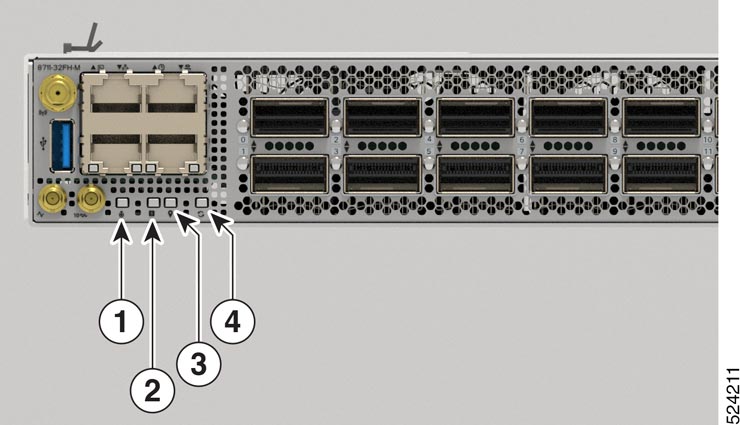
Figure 1. Chassis LEDs - Front View of Cisco 8711-32FH-M

1

Attention

2

Status

3

GPS

4

Synchronization

Table 1. Chassis LED Descriptions
LED Color Status

Attention

Flashing blue

The operator has activated this LED to identify this chassis.

Off

This chassis is not being identified.

Status

Green

The module is operational and has no active major or critical alarms.

Flashing Green

The auto or manual FPD upgrade is in progress.

Amber

The module is in one of the following states:

  • Power cycle

  • Reload or reimage

  • Shutdown

Flashing Amber

The module has minor alarm.

Red

Power-up failure which prevents the CPU from booting.

Flashing Red

The module has active major or critical alarms.

Off

The module is powered-off.

GPS

Green

The GPS interface is provisioned and frequency, time of day and phase inputs are all operating correctly.

Off

The GPS interface is not provisioned, or the GPS inputs are not working correctly.

Synchronization

Green

Time core is synchronized to an external source including IEEE1588.

Amber

The system is running in holdover or free-run mode and it is not synchronized to an external interface.

Off

The centralized frequency or time and phase distribution is not enabled.

Port Status LEDs

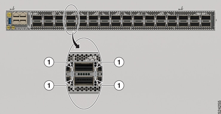
Each port has an LED. The following table describes port status LEDs.

Figure 2. Port Status LED - Cisco 8711-32FH-M Chassis

1

400G Port Status LED

Table 2. Port Status LEDs (one per port)

LED Color

Description

Off

Port is administratively shut down.

Amber

Port is administratively enabled and the link is down.

Green

Port is administratively enabled and the link is up.

LEDs for Cisco 8712 Router

Chassis LED

This section describes the chassis LED and its status.

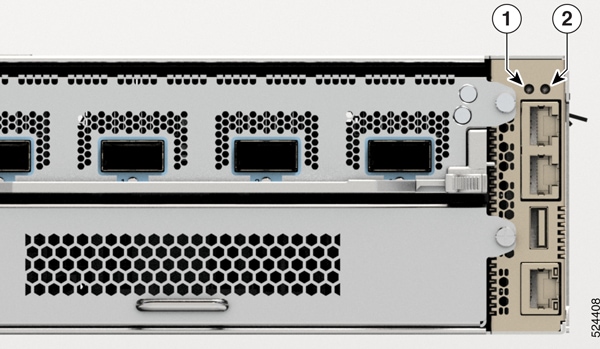
Figure 3. Chassis LEDs - Front View of Cisco 8712-MOD-M

1

Attention

2

Status

Table 3. Chassis LED Descriptions
LED Color Status

Attention

Flashing Blue

The operator has activated this LED to identify this chassis.

Off

The operator has not activated this LED.

MPA LEDs

The Status LED and the Attention LED are located on the bottom of the MPA. The Link LEDs for each port are located on the right-side of the MPA, next to the ejector lever.

MPA LEDs - 8K-MPA-4D

1

Attention

2

Status

3

Port Link

MPA LEDs - 8K-MPA-16H

1

Attention

2

Status

3

Port Link

MPA LEDs - 8K-MPA-16Z2D

1

Attention

2

Status

3

Link (Port 0-15)

4

Link (Port 16 and 18)

5

Link (Port 17 and 19)

Table 4. MPA LED Descriptions
LED Color Status

Attention

Flashing Blue

The operator has activated this LED to identify this module in the chassis.

Off

This module is not identified by the operator.

Status

Solid Amber

The module is in one of the following states:

  • Booting up

  • Shutting down

  • Power cycling

Solid Green

The module is operational with no issues.

Solid Red

The module has failed to power-up

Flashing Green

Auto or manual FPD upgrade is in-progress.

Flashing Red

The module has an active major or critical alarm.

Flashing Amber

The module has an active minor alarm.

Off

The module is in one of the following states:

  • The module is in shutdown state by using either shutdown location location command in the EXEC mode or by using the hw-module shutdown location location command in the Config mode.

  • While the card is in running state, the ejector lever is opened that triggers the auto-shutdown operation for the module.

  • The module is placed in shutdown state by the software due to a hardware fault or a critical alarm condition.

Note


While in this state, the module can be safely removed from the router.

Port (for each port)

Green

The port is administratively enabled and the link is up.

Amber

The port is administratively enabled and the link is down.

Off

The port is administratively shut down.

Fan LED

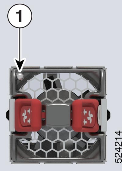
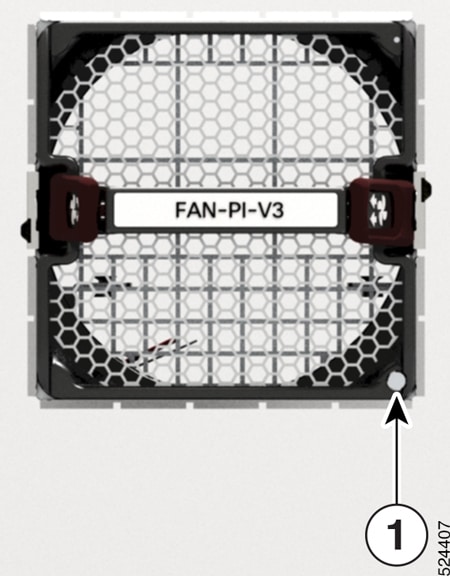
Fan modules are located on the back of the chassis. Each fan module has a Status LED.

Figure 4. Fan LED - Cisco 8711-32FH-M Chassis
Figure 5. Fan LED - Cisco 8712-MOD-M Chassis

1

Fan Status LED

Table 5. Fan LED Descriptions

LED

Color

Status

Status

Green

Fan is operating normally.

Amber

Fan is inserted and pending to come online.

Flashing Amber

The module is in one of these states:

  • Fan speed (RPM) is outside normal range.

  • The module has a minor, major, or critical alarm.

Flashing Blue

The module is identified or activated.

Off

Fan is not receiving power.

Power Supply LEDs

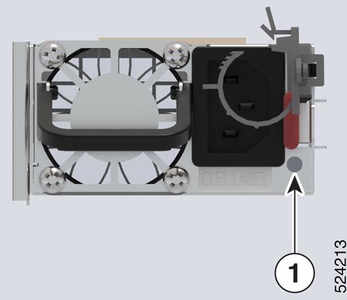
Power modules are located on the back side of the chassis. Each power module has a Status LED.

Figure 6. Cisco 8711-32FH-M Power Supply LED
Figure 7. Cisco 8712-MOD-M DC Power Supply LED
Figure 8. Cisco 8712-MOD-M AC Power Supply LED

1

Status LED

Table 6. Power Supply LED Descriptions

LED

Color

Status

Status

Green

Power supply is on and transmitting power to the router.

Flashing Green (2 Hz)

Power supply is connected to input power source but not transmitting power to the router.

Flashing Green (4 Hz)

Power Supply Unit firmwire upgrade in-progress.

Amber

Power supply failure, due to one of these conditions:

  • Over voltage

  • Over current

  • Over temperature

  • Fan failure

Flashing Amber (1 Hz)

Power supply is operating but a warning condition has occurred, due to one of these conditions:

  • High temperature

  • High power

  • Slow fan

Off

Power supply units are not receiving power.