Cisco 8700 Series Routers Overview

Cisco 8700 Series Routers

Cisco 8712-MOD-M

The Cisco 8712-MOD-M is a K100-based, 2-RU router that provides 6.4 Tbps of network bandwidth and supports fixed architecture with I/O diversity.

The front of the chassis has four pluggable Modular Port Adapters (MPAs) slots.
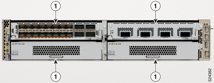
Figure 1. Cisco 8712-MOD-M - Front View

1

Modular Port Adapters (MPAs) Slots

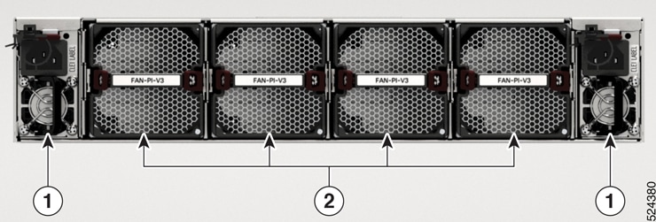
Figure 2. Cisco 8712-MOD-M - Rear View

1

Power Supply Slots

2

Fan Slots

This table details the modules available in the rear of the chassis:

Table 1. Cisco 8712-MOD-M Router Rear View Details

Module Type

Description

Airflow Directions

Module Color

Power Supply Modules

Two 2KW power modules that operate at 12 V capacity, providing 1+1 power redundancy and different AC/DC inputs capabilities.

Port-Side-Intake (PSI)

Burgundy

Port-Side-Exhaust (PSE)

Cisco Safety Blue

Fan Modules

Four 80mm counter-rotating double-fan trays providing N+1 redundancy. The fan modules can be removed individually.

Port-Side-Intake (PSI)

Burgundy

Port-Side-Exhaust (PSE)

Cisco Safety Blue


Note


The airflow direction must be the same for all power supply and fan modules in the chassis. That is, you must use PSI power modules with PSI fan modules and PSE power module with PSE fan modules only.


The following table describes the Cisco 8712-MOD-M router components, and the supported quantity.

Table 2. Cisco 8712-MOD-M Router Components

Component

Quantity

MPA

4

Fan module

4

Power module

2 AC or 2 DC

Cisco 8711-32FH-M

The Cisco 8711-32FH-M is a P100 silicon chip-based router that provides 12.8 Tbps of network bandwidth. The Cisco 8711-32FH-M is a fixed-port, high density, one rack-unit form factor router. Supported ports include 32 QSFP56-DD 400GbE ports. It includes HBM/2.5D for advanced performance, and supports Cisco 400GbE Digital Coherent Optical Modules.

Cisco 8711-32FH-M Router Front View

The front of the chassis has the following:

  • 32 x QSFP56-DD 400GbE ports or 16 x 800G QSFP-DD800 ports


    Note


    Each of these ports can support 2x400GbE or 1x800G traffic. You can have any combination of the available 400GbE or 800G ports that must not exceed the total bandwidth of 12.8 Tbps. All the 400GbE ports support breakout operation.


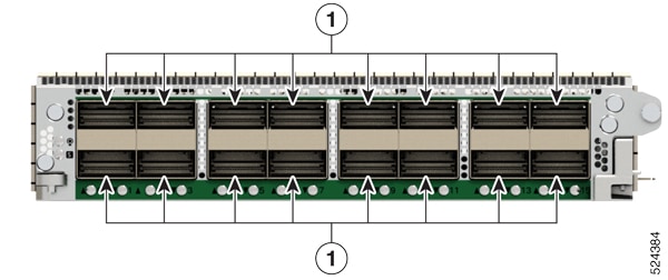
Figure 3. Cisco 8711-32FH-M - Front View

1

32 QSFP56-DD 400GbE ports

Note


The top row is 16 x 800G QSFP-DD800 capable ports.

Cisco 8711-32FH-M Router Rear View

This table details the modules available in the rear of the chassis:

Table 3. Cisco 8711-32FH-M Router Rear View Details

Module Type

Description

Airflow Directions

Module Color

Power Supply Modules

Two 2KW power modules that operate at 12 V capacity, providing 1+1 power redundancy and different AC/DC inputs capabilities.

Port-Side-Intake (PSI)

Burgundy

Port-Side-Exhaust (PSE)

Cisco Safety Blue

Fan Modules

Six 40mm counter-rotating double-fan trays providing N+1 redundancy. The fan modules can be removed individually.

Port-Side-Intake (PSI)

Burgundy

Port-Side-Exhaust (PSE)

Cisco Safety Blue


Note


The chassis does not come preloaded with fans and power supply units.


Figure 4. Cisco 8711-32FH-M - Rear View

1

Power Supply

2

Fans


Note


The fans and power modules illustrated have Port-Side-Intake (PSI) configuration.


Modular Port Adapters Overview

Cisco 8700 Series Routers support the following Modular Port Adapters (MPAs):

Table 4. Supported MPAs on Cisco 8700 Router
MPA PIDs Transceivers

8K-MPA-4D

QSFP-DD

8K-MPA-16H

QSFP28

8K-MPA-16Z2D

QSFP-DD/zSFP56+

8K-MPA-4D

The following image explains the port details of the MPA:

Figure 5. 8K-MPA-4D Port Details

1

QSFP-DD (Ports 0, 1, 2, and 3)

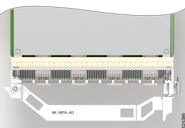
Figure 6. 8K-MPA-4D Handle

The 8K-MPA-4D is a pluggable card that provides 4 interface ports that can support QSFP-DD 400GbE, 200GbE, or 100GbE modules

8K-MPA-16H

The following image displays the MPA PID and explains the port configuration details of the MPA:

Figure 7. 8K-MPA-16H Port Details

1

QSFP28 100G (Ports 0, 1, 2, 3, 4, 5, 6, 7, 8, 9, 10, 11, 12, 13, 14, and 15)

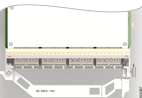
Figure 8. 8K-MPA-16H Handle

The 8K-MPA-16H is a pluggable card that provides 16 interface ports that supports QSFP-28 100GbE module.

8K-MPA-16Z2D

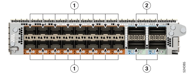
The following image displays the MPA PID and explains the port details of the MPA:

Figure 9. 8K-MPA-16Z2D

1

SFP 50GbE, 25GbE, 10GbE, or 1GbE (Ports 0, 1, 2, 3, 4, 5, 6, 7, 8, 9, 10, 11, 12, 13, 14, and 15)

2

QSFP-DD 400GbE, 200GbE, or 100GbE (Ports 16 and 18)

3

QSFP-DD 200GbE or 100GbE (Ports 17 and 19)

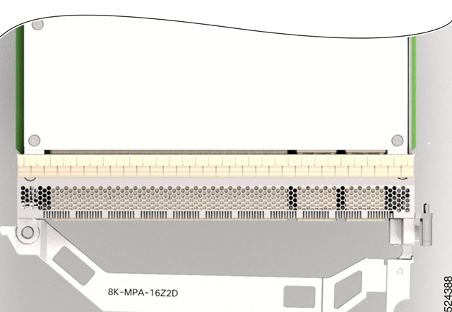
Figure 10. 8K-MPA-16Z2D Handle

The 8K-MPA-16Z2D is a pluggable card that provides 20 interface ports that can support up to:

  • 4 ports of QSFP-DD and 16 ports of SFP

  • 16 ports (0-15) of SFP 50GbE, 25GbE, 10GbE, or 1GbE modules

  • 2 ports (16 and 18) of QSFP-DD 400GbE, 200GbE, or 100GbE modules

  • 2 ports (17 and 19) of QSFP-DD 200GbE or 100GbE modules

When port 16 and 18 has a 400G QSFP-DD, then the other two ports (17 and 19) cannot be used.


Note


The 8K-MPA-16Z2D MPA does not support auto-negotiation when using the 400G optics.


Note


You can only perform consecutive MPA reloads in Cisco 8700 Series Routers after the MPA has been operational for a few minutes following the first reload. Reloading the MPA again without waiting may result in abnormal failures of the subsequent reload.


Temperature and Physical Specifications

For temperature and physical specifications, refer to the Physical characteristics table in the Cisco 8700 Router Data Sheet.

Weight and Power Consumption

For weight and power consumption, refer to the Physical characteristics table in the Cisco 8700 Router Data Sheet.

Airflow Direction

The Cisco 8700 series routers support these configurations:

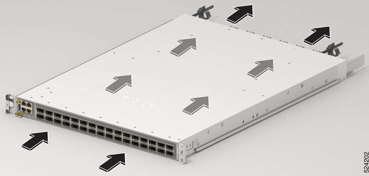
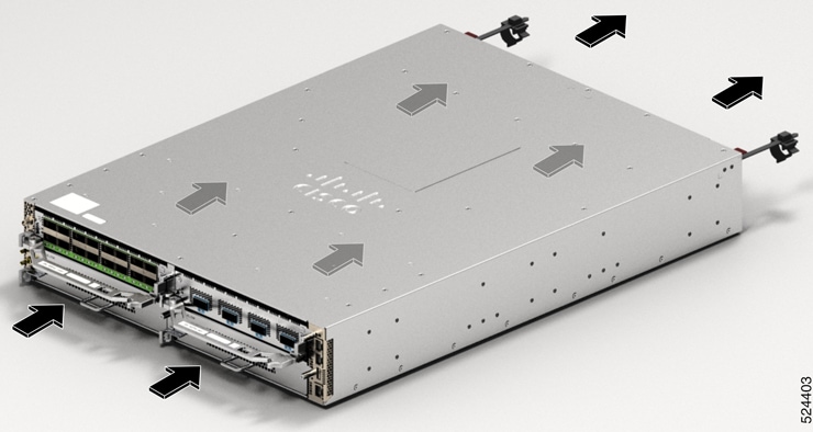
  • Post-Side Intake (PSI) configuration - the airflow through both the fan trays and power supplies is from the front-side to the rear-side. In PSI configuration, the power and fan modules are in Burgundy color.

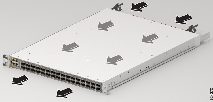
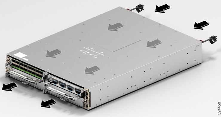
  • Post-Side Exhaust (PSE) configuration - the airflow through both the fan trays and power supplies is from the rear-side to the front-side. In PSE configuration, the power and fan modules are in Cisco Safety Blue color.

Figure 11. Airflow Direction for Cisco 8711-32FH-M Router in PSI Configuration

Figure 12. Airflow Direction for Cisco 8711-32FH-M Router in PSE Configuration

Figure 13. Airflow Direction for Cisco 8712-MOD-M Router in PSI Configuration

Figure 14. Airflow Direction for Cisco 8712-MOD-M Router in PSE Configuration

To ensure proper airflow for the router in your facility, position the router with its air intake on a cold aisle and the air exhaust on a hot aisle.


Note


The airflow direction must be the same for all power supply and fan modules in the chassis.


Maximum Power Available to Router

The maximum power available to the router depends on the following factors:

  • the input power from the power source

  • the number of Power Supply Units (PSUs)

  • the output capabilities of the PSUs

  • the power redundancy mode

The following table lists the amount of power available for Cisco 8700 series routers from all available power trays.

Table 5. Maximum Power Available

Number of PSUs

Combined Mode (No redundancy)

1+1 Redundancy Mode (with Single Supply Loss)

1

2KW

2

4KW

2KW


Note


In Cisco 8700 series routers, when the AC power supply unit operates at the low line voltage range of 90VAC to 140VAC, the router does not support 1+1 redundancy mode. The low line voltage maximum power per AC power supply unit is 1KW. Thus, the total power of two AC power supply units at the low line voltage is 2KW. Therefore, you must have two AC power supply units for the router to operate at low line voltage.


Supported Optics


Note


To determine which transceivers and cables are supported by this router, refer to the Transceiver Module Group (TMG) Compatibility Matrix Tool:

https://tmgmatrix.cisco.com/