Configure Segment Routing for IS-IS Protocol

Integrated Intermediate System-to-Intermediate System (IS-IS), Internet Protocol Version 4 (IPv4), is a standards-based Interior Gateway Protocol (IGP). The Cisco IOS XR software implements the IP routing capabilities described in International Organization for Standardization (ISO)/International Engineering Consortium (IEC) 10589 and RFC 1995, and adds the standard extensions for single topology and multitopology IS-IS for IP Version 6 (IPv6).

This module provides the configuration information used to enable segment routing for IS-IS.


Note


For additional information on implementing IS-IS on your Cisco 8000 Series Router, see the Implementing IS-IS module in the Routing Configuration Guide for Cisco 8000 Series Routers.


Enabling Segment Routing for IS-IS Protocol

Segment routing on the IS-IS control plane supports the following:

  • IPv4 and IPv6 control plane

  • Level 1, level 2, and multi-level routing

  • Prefix SIDs for host prefixes on loopback interfaces

  • Adjacency SIDs for adjacencies

  • MPLS penultimate hop popping (PHP) and explicit-null signaling

This task explains how to enable segment routing for IS-IS.

Before you begin

Your network must support the MPLS Cisco IOS XR software feature before you enable segment routing for IS-IS on your router.


Note


You must enter the commands in the following task list on every IS-IS router in the traffic-engineered portion of your network.


SUMMARY STEPS

  1. configure
  2. router isis instance-id
  3. address-family { ipv4 | ipv6 } [ unicast ]
  4. metric-style wide [ level { 1 | 2 }]
  5. router-id loopback loopback interface used for prefix-sid
  6. segment-routing mpls [sr-prefer]
  7. exit
  8. Use the commit or end command.

DETAILED STEPS

  Command or Action Purpose

Step 1

configure

Example:


RP/0/RP0/CPU0:router# configure

Enters mode.

Step 2

router isis instance-id

Example:


RP/0/RP0/CPU0:router(config)# router isis isp

Enables IS-IS routing for the specified routing instance, and places the router in router configuration mode.

Note

 
You can change the level of routing to be performed by a particular routing instance by using the is-type router configuration command.

Step 3

address-family { ipv4 | ipv6 } [ unicast ]

Example:


RP/0/RP0/CPU0:router(config-isis)# address-family ipv4 unicast

Specifies the IPv4 or IPv6 address family, and enters router address family configuration mode.

Step 4

metric-style wide [ level { 1 | 2 }]

Example:


RP/0/RP0/CPU0:router(config-isis-af)# metric-style wide level 1

Configures a router to generate and accept only wide link metrics in the Level 1 area.

Step 5

router-id loopback loopback interface used for prefix-sid

Example:

RP/0/(config-isis-af)#router-id loopback0

Configures router ID for each address-family (ipv4/ipv6).

Step 6

segment-routing mpls [sr-prefer]

Example:


RP/0/RP0/CPU0:router(config-isis-af)# segment-routing mpls

Segment routing is enabled by the following actions:

  • MPLS forwarding is enabled on all interfaces where IS-IS is active.

  • All known prefix-SIDs in the forwarding plain are programmed, with the prefix-SIDs advertised by remote routers or learned through local or remote mapping server.

  • The prefix-SIDs locally configured are advertised.

Use the sr-prefer keyword to set the preference of segment routing (SR) labels over label distribution protocol (LDP) labels.

Step 7

exit

Example:


RP/0/RP0/CPU0:router(config-isis-af)# exit
RP/0/RP0/CPU0:router(config-isis)# exit

Step 8

Use the commit or end command.

commit —Saves the configuration changes and remains within the configuration session.

end —Prompts user to take one of these actions:
  • Yes — Saves configuration changes and exits the configuration session.

  • No —Exits the configuration session without committing the configuration changes.

  • Cancel —Remains in the configuration session, without committing the configuration changes.

What to do next

Configure the prefix SID.

Configuring a Prefix-SID on the IS-IS Enabled Loopback Interface

Table 1. Feature History Table

Feature Name

Release Information

Feature Description

Disable Penultimate Hop Popping

Release 7.5.4

You can now disable the penultimate hop popping (PHP) without adding an explicit-Null label.

In earlier releases, you could disable PHP only by adding an explicit-Null label using the explicit-null keyword.

The feature introduces the php-disable keyword under the prefix-sid command.

A prefix segment identifier (SID) is associated with an IP prefix. The prefix SID is manually configured from the segment routing global block (SRGB) range of labels. A prefix SID is configured under the loopback interface with the loopback address of the node as the prefix. The prefix segment steers the traffic along the shortest path to its destination.

A prefix SID can be a node SID or an Anycast SID. A node SID is a type of prefix SID that identifies a specific node. An Anycast SID is a type of prefix SID that identifies a set of nodes, and is configured with n-flag clear. The set of nodes (Anycast group) is configured to advertise a shared prefix address and prefix SID. Anycast routing enables the steering of traffic toward multiple advertising nodes. Packets addressed to an Anycast address are forwarded to the topologically nearest nodes.

Strict-SPF SIDs are used to forward traffic strictly along the SPF path. IS-IS advertises the SR Algorithm sub Type Length Value (TLV) (in the SR Router Capability SubTLV) to include both algorithm 0 (SPF) and algorithm 1 (Strict-SPF). Strict-SPF SIDs are also used to program the backup paths for prefixes, node SIDs, and adjacency SIDs.

Penultimate-Hop-Popping (PHP) can be disabled for the Prefix SID. In this case, the penultimate hop does not pop the Prefix-SID before delivering the packet to the node that advertised the Prefix-SID; it is forwarded intact to the next hop. This can be useful in situations where the label needs to be retained for certain purposes, such as for traffic engineering or QoS policies.

The prefix SID is globally unique within the segment routing domain.

This task explains how to configure prefix segment identifier (SID) index or absolute value on the IS-IS enabled Loopback interface.

Before you begin

Ensure that segment routing is enabled on the corresponding address family.

SUMMARY STEPS

  1. configure
  2. router isis instance-id
  3. interface Loopback instance
  4. address-family { ipv4 | ipv6 } [ unicast ]
  5. prefix-sid [algorithm algorithm-number] {index SID-index | absolute SID-value } [n-flag-clear ] [explicit-null ] [php-disable]
  6. Use the commit or end command.

DETAILED STEPS

  Command or Action Purpose

Step 1

configure

Example:


RP/0/RP0/CPU0:router# configure

Enters XR Config mode.

Step 2

router isis instance-id

Example:


RP/0/RP0/CPU0:router(config)# router isis 1

Enables IS-IS routing for the specified routing instance, and places the router in router configuration mode.

  • You can change the level of routing to be performed by a particular routing instance by using the is-type router configuration command.

Step 3

interface Loopback instance

Example:


RP/0/RP0/CPU0:router(config-isis)# interface Loopback0

Specifies the loopback interface and instance.

Step 4

address-family { ipv4 | ipv6 } [ unicast ]

Example:

The following is an example for ipv4 address family:

RP/0/RP0/CPU0:router(config-isis-if)# address-family ipv4 unicast

Specifies the IPv4 or IPv6 address family, and enters router address family configuration mode.

Step 5

prefix-sid [algorithm algorithm-number] {index SID-index | absolute SID-value } [n-flag-clear ] [explicit-null ] [php-disable]

Example:


RP/0/RP0/CPU0:router(config-isis-if-af)# prefix-sid index 1001


RP/0/RP0/CPU0:router(config-isis-if-af)# prefix-sid absolute 17001

Configures the prefix-SID index or absolute value for the interface.

Specify algorithm algorithm-number to configure SR Flexible Algorithm. See Enabling Segment Routing Flexible Algorithm.

Specify index SID-index for each node to create a prefix SID based on the lower boundary of the SRGB + the index.

Specify absolute SID-value for each node to create a specific prefix SID within the SRGB.

By default, the n-flag is set on the prefix-SID, indicating that it is a node SID. For specific prefix-SID (for example, Anycast prefix-SID), enter the n-flag-clear keyword. IS-IS does not set the N flag in the prefix-SID sub Type Length Value (TLV).

To disable penultimate-hop-popping (PHP) and add explicit-Null label, enter explicit-null keyword. IS-IS sets the E flag in the prefix-SID sub TLV. Any upstream neighbor of the Prefix-SID originator replaces the Prefix-SID with a Prefix-SID having an Explicit NULL value.

To disable penultimate-hop-popping (PHP), enter php-disable keyword. IS-IS sets the P flag in the prefix-SID sub TLV. The penultimate hop will not pop the Prefix-SID before delivering the packet to the node that advertised the Prefix-SID.

Step 6

Use the commit or end command.

commit —Saves the configuration changes and remains within the configuration session.

end —Prompts user to take one of these actions:
  • Yes — Saves configuration changes and exits the configuration session.

  • No —Exits the configuration session without committing the configuration changes.

  • Cancel —Remains in the configuration session, without committing the configuration changes.

Verify the prefix-SID configuration:

RP/0/RP0/CPU0:router# show isis database verbose 

IS-IS 1 (Level-2) Link State Database
LSPID                 LSP Seq Num  LSP Checksum  LSP Holdtime  ATT/P/OL
router.00-00        * 0x0000039b   0xfc27        1079            0/0/0
  Area Address: 49.0001
  NLPID:        0xcc
  NLPID:        0x8e
  MT:           Standard (IPv4 Unicast)
  MT:           IPv6 Unicast                                     0/0/0
  Hostname:     router
  IP Address:   10.0.0.1
  IPv6 Address: 2001:0db8:1234::0a00:0001
  Router Cap:   10.0.0.1, D:0, S:0
    Segment Routing: I:1 V:1, SRGB Base: 16000 Range: 8000
    SR Algorithm: 
      Algorithm: 0
      Algorithm: 1
<...>
  Metric: 0          IP-Extended 10.0.0.1/32
    Prefix-SID Index: 1001, Algorithm:0, R:0 N:1 P:0 E:0 V:0 L:0
    Prefix-SID Index: 101, Algorithm:1, R:0 N:1 P:0 E:0 V:0 L:0
<...>


Overriding MPLS Imposition (IP-to-MPLS) via Service Layer API (SL-API)

Table 2. Feature History Table

Feature Name

Release Information

Feature Description

Overriding MPLS Imposition (IP-to-MPLS) via Service Layer API (SL-API)

Release 24.2.11

In scenarios where SR-prefer is enabled, this feature allows you to specify SR prefixes through an Access Control List where their imposition forwarding entry (IP-to-MPLS) gives preference to SL-API, instead of the SR native LSP.

The labeled forwarding entries (MPLS-to-MPLS or MPLS-to-IP) continue to follow the SR native LSP.

This feature introduces the following command under Router RIB AF configuration mode:

segment-routing mpls preserve-label-forwarding access-listacl_name [apply-inverse]


Note


For detailed information about Service Layer API (SL-API), refer to "Use Service Layer API to Bring your Controller on Cisco IOS XR Router" of the Programmability Configuration Guide for Cisco 8000 Series Routers.

Usage Guidelines and Limitations

The following usage guidelines and limitations apply:

  • This feature is applicable when an SR prefix destination is also programmed via SL-API and “sr-prefer” is also enabled due to the presence of other prefixes with both SR and LDP LSPs.

  • If the feature is configured for selected (allowed) prefixes, the “sr-prefer” configuration is ignored and the imposition forwarding entry follows the SL-API path instead of the SR native LSP.

  • If the feature is not configured, or if a prefix is not allowed for SL-API steering, the “sr-prefer” configuration is honored and the imposition forwarding entry follows the SR native LSP.

  • When there is a single source of programming for a destination (SR or SL-API), this feature has no impact on the forwarding.

  • This feature is supported for programming of IPv4 SR prefixes.

  • This feature is supported for programming of IPv6 SR prefixes.

  • This feature does not support forwarding of traffic to IPv4 destinations recursing onto IPv6 next-hops steered over SL-API paths (BGPv4 over SRMPLS-v6).

  • Redistribution of SL-API imposition route into another protocol is not supported.

  • SR native and SL-API paths must always be labelled.

  • The set of prefixes allowed for SR and LDP must be disjointed from the set of prefixes allowed for SR and SL-API. SR/SL-API and SR/LDP can co-exist across different SR prefixes.

Use Case

Assume a node is part of a network with SR and LDP enabled concurrently (ships-in-the-night) with preference to SR over LDP when both LSPs are present (sr-prefer).

The network operator relies on a controller to program a desired traffic-engineered path for specific prefix destinations using SL-API. The following forwarding behaviors are expected at the node programmed via SL-API:

  • Imposition forwarding entry (IP-to-MPLS) gives preference to the SL-API LSP

  • Labeled forwarding entries (MPLS-to-MPLS or MPLS-to-IP) follow the SR native LSP

Transport Without SL-API Injection

Consider the following :

  • A network with SR and LDP enabled concurrently

  • Nodes are configured with SR-prefer enabled

  • Prefix 10.1.1.2/32 (SR prefix SID 16002) is programmed with SR native LSP

  • Prefix 10.1.1.3/32 (SR prefix SID 16003) is programmed with SR native LSP

  • Prefix 10.1.1.4/32 (SR prefix SID 16004) is programmed with both SR native and LDP LSPs

  • When required, a controller is used to program a desired traffic-engineered path for allowed destination prefixes via an SL-API:

    • Allowed prefixes for controller steering: 10.1.1.2/32, 10.1.1.3/32

    • Not allowed prefix for controller steering: 10.1.1.4/32

When the controller does not trigger an SL-API path for allowed prefixes, the imposition forwarding entry follows the SR native LSP instead of the LDP LSP (as a result of configuring sr-prefer). The Swap/Pop forwarding entries are programmed to follow both SR native and LDP LSPs.

For SR prefixes 10.1.1.2/32 and 10.1.1.3/32:

  • Imposition (IP2MPLS):

    • SR Prefix SID push forwarding entry programmed by IGP

  • Swap/Pop (MPLS2MPLS/MPLS2IP):

    • SR prefix SID local label swap/pop forwarding entry programmed by IGP

For SR prefix 10.1.1.4/32:

  • Imposition (IP2MPLS):

    • SR Prefix SID push forwarding entry programmed by IGP

  • Swap/Pop (MPLS2MPLS/MPLS2IP):

    • SR prefix SID local label swap/pop forwarding entry programmed by IGP

    • LDP local label swap/pop forwarding entry programmed by LDP

Transport After SL-API Injection

When the controller triggers an SL-API path for an allowed destination prefix (for example 10.1.1.2), the imposition forwarding entry will follow the SL-API LSP instead of the SR native LSP.

The imposition forwarding entry for allowed prefixes but not programmed by SL-API (for example 10.1.1.3/32), or not allowed prefixes (for example, 10.1.1.4), will follow the SR native LSP.

The Swap/Pop forwarding entries for the SR-only prefixes (10.1.1.2/32, 10.1.1.3/32) continue to be programmed by SR.

The Swap/Pop forwarding entries for the SR/LDP prefix (10.1.1.4/32) continue to be programmed by both SR and LDP.

For Prefix 10.1.1.2/32:

  • Imposition (IP2MPLS):

    • Label stack push forwarding entry programed by SL-API

  • Swap/Pop (MPLS2MPLS/MPLS2IP):

    • SR prefix SID local label swap/pop forwarding entry programmed by IGP

There are no changes to the forwarding entries for prefixes 10.1.1.3/32 and 10.1.1.4/32.

Configuration

To enable overriding of MPLS label imposition via SL-API, use the segment-routing mpls preserve-label-forwarding access-list acl_name [apply-inverse] command under router rib address-family {ipv4|ipv6} configuration mode.

Example

The following example shows how to allow IPv4 SR prefix 10.1.1.2/32 to have it MPLS imposition forwarding entry to be override via SL-API:

RP/0/RP0/CPU0:ios(config)# ipv4 access-list SL-API-PREFER-ALLOWED-PFX
RP/0/RP0/CPU0:ios(config-ipv4-acl)# 10 permit 10.1.1.2
RP/0/RP0/CPU0:ios(config-ipv4-acl)# exit

RP/0/RP0/CPU0:ios(config)# router rib address-family ipv4
RP/0/RP0/CPU0:ios(config-rib-afi)# segment-routing mpls preserve-label-forwarding access-list SL-API-PREFER-ALLOWED-PFX

The following example shows how to allow any IPv4 SR prefix except 10.1.1.2/32 to have it MPLS imposition forwarding entry to be override via SL-API:

RP/0/RP0/CPU0:ios(config)# ipv4 access-list SL-API-PREFER-DISALLOWED-PFX
RP/0/RP0/CPU0:ios(config-ipv4-acl)# 10 permit 10.1.1.2
RP/0/RP0/CPU0:ios(config-ipv4-acl)# exit

RP/0/RP0/CPU0:ios(config)# router rib address-family ipv4
RP/0/RP0/CPU0:ios(config-rib-afi)# segment-routing mpls preserve-label-forwarding access-list SL-API-PREFER-DISALLOWED-PFX apply-inverse

Verification

Consider the following SR prefix as allowed to be steered over an SL-API path:

  • Prefix: 10.1.1.1/32

  • Prefix SID: 20000

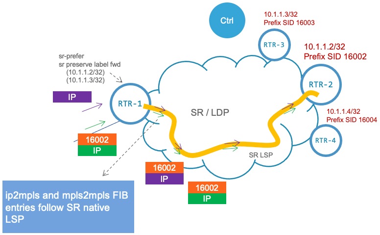
The SR native LSP programmed at a node in the network is as follows:

  • Local label: 20000

  • ECMP:

    • Path0 – out label: 20000; out int: Bundle-Ether20131

    • Path1 – out label: 20000; out int: Bundle-Ether20132

    • Path2 – out label: 20000; out int: Bundle-Ether20133

    • Path3 – out label: 20000; out int: Bundle-Ether20134

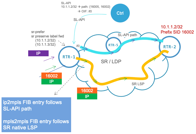
The SL-API LSP to be programmed by the controller at the same node is as follows:

  • Local label: 100051 (dynamically allocated)

  • Weighted ECMP:

    • Path0 – out label: 24000, 18001; out int: Bundle-Ether2012; weight: 1

    • Path1 – out label: 24000, 18001; out int: Bundle-Ether2013; weight: 2

    • Path2 – out label: 24001, 18001; out int: Bundle-Ether2014; weight: 4

    • Path3 – out label: 24001, 18001; out int: Bundle-Ether2015; weight: 8

The following sequence of show command outputs can be used to verify the programming of the imposition forwarding entry when an SL-API path is present.

The following output shows the RIB entry for an allowed prefix highlighting the fields to indicate that overriding of MPLS label imposition via SL-API is enabled:

Router# show route 10.1.1.1/32 detail 

Routing entry for 10.1.1.1/32
  Known via "isis 0", distance 115, metric 500, labeled SR (label forwarding preserve), type level-2
  Installed Jul 30 21:23:50.539 for 01:43:09
  Routing Descriptor Blocks
    100.201.201.2, from 199.1.0.2, via Bundle-Ether20131
      Route metric is 500
      Label: 0x4e20 (20000)
      Tunnel ID: None
      Binding Label: None
      Extended communities count: 0
      Path id:4	      Path ref count:0
      NHID:0x0(Ref:0)
      MPLS eid:0x109c700000001
    101.201.201.2, from 199.1.0.2, via Bundle-Ether20132
      Route metric is 500
      Label: 0x4e20 (20000)
      Tunnel ID: None
      Binding Label: None
      Extended communities count: 0
      Path id:3	      Path ref count:0
      NHID:0x0(Ref:0)
      MPLS eid:0x109c700000001
    102.201.201.2, from 199.1.0.2, via Bundle-Ether20133
      Route metric is 500
      Label: 0x4e20 (20000)
      Tunnel ID: None
      Binding Label: None
      Extended communities count: 0
      Path id:2	      Path ref count:0
      NHID:0x0(Ref:0)
      MPLS eid:0x109c700000001
    103.201.201.2, from 199.1.0.2, via Bundle-Ether20134
      Route metric is 500
      Label: 0x4e20 (20000)
      Tunnel ID: None
      Binding Label: None
      Extended communities count: 0
      Path id:1	      Path ref count:0
      NHID:0x0(Ref:0)
      MPLS eid:0x109c700000001
  Route version is 0x47 (71)
  Local Label: 0x4e20 (20000)
  IP Precedence: Not Set
  QoS Group ID: Not Set
  Flow-tag: Not Set
  Fwd-class: Not Set
  Route Priority: RIB_PRIORITY_NON_RECURSIVE_MEDIUM (7) SVD Type RIB_SVD_TYPE_LOCAL
  Download Priority 1, Download Version 1793240
  Route eid: 0x109c700000001
  No advertising protos.

The following output shows the imposition forwarding entry programmed via SL-API (rewrite owner) in LSD. Observe the programmed paths and their parameters (output interface, output labels, and weight).

Router# show mpls lsd forwarding ipv4 detail | begin 10.1.1.1/32

'default':4U, 10.1.1.1/32, (100051)[SR Merge], 4 Paths, 
       Owner=Static(A):Service-layer
   1/4: IPv4_STACK, 'default':4U, BE2012, BSID: NO_LABEL, nh=100.201.200.2, lbls={ 24000, 18001 }  
            lbl flags= {0x0 0x0} ()}, ext_flags=0x0 path_flags=0x0 
            nh-id=0x0, path-id=0, backup-path-id=0, load-metric=32, parent-intf=None, path-set-id=0, path-priority=0
            Inner Stack Flags:  { 0x0}
            MPLS eid: N/A
   2/4: IPv4_STACK, 'default':4U, BE2013, BSID: NO_LABEL, nh=101.201.200.2, lbls={ 24000, 18001 }  
            lbl flags= {0x0 0x0} ()}, ext_flags=0x0 path_flags=0x0 
            nh-id=0x0, path-id=0, backup-path-id=0, load-metric=64, parent-intf=None, path-set-id=0, path-priority=0
            Inner Stack Flags:  { 0x0}
            MPLS eid: N/A
   3/4: IPv4_STACK, 'default':4U, BE2014, BSID: NO_LABEL, nh=102.201.200.2, lbls={ 24001, 18001 }  
            lbl flags= {0x0 0x0} ()}, ext_flags=0x0 path_flags=0x0 
            nh-id=0x0, path-id=0, backup-path-id=0, load-metric=128, parent-intf=None, path-set-id=0, path-priority=0
            Inner Stack Flags:  { 0x0}
            MPLS eid: N/A
   4/4: IPv4_STACK, 'default':4U, BE2015, BSID: NO_LABEL, nh=103.201.200.2, lbls={ 24001, 18001 }  
            lbl flags= {0x0 0x0} ()}, ext_flags=0x0 path_flags=0x0 
            nh-id=0x0, path-id=0, backup-path-id=0, load-metric=256, parent-intf=None, path-set-id=0, path-priority=0
            Inner Stack Flags:  { 0x0}
            MPLS eid: N/A
      BCDL priority:1, LSD queue:9, version:178429,
      flags: 0x8, fwd_flags: 0x100 (sr_lbl_fwd_preserve), 
      Installed Jul 30 21:26:25.111 (01:42:45 ago)
      Prefix eid: 0x1275100000001

. . .

The following output shows that the CEF imposition forwarding entry prefers the SL-API path.

Router# show cef 10.1.1.1/32 detail location 0/0/CPU0

10.1.1.1/32, version 178429, internal 0x1000001 0x110 (ptr 0xa0ea1428) [3], 0x0 (0x1182a378), 0xa28 (0x202c3ba8)
 Updated Jul 30 21:26:25.635 
 local adjacency to Bundle-Ether2012

 Prefix Len 32, traffic index 0, precedence n/a, priority 1, encap-id 0x1275100000001
  gateway array (0x1d140ef8) reference count 750, flags 0x68, source lsd (5), 1 backups
                [251 type 5 flags 0x8401 (0x8c18bda0) ext 0x0 (0x0)]
  LW-LDI[type=5, refc=3, ptr=0x1182a378, sh-ldi=0x8c18bda0]
  gateway array update type-time 1 Jul 30 21:26:25.532
 LDI Update time Jul 30 21:26:25.532
 LW-LDI-TS Jul 30 21:26:25.635
   via 100.201.200.2/32, Bundle-Ether2012, 7 dependencies, weight 32, class 0 [flags 0x0]
    path-idx 0 NHID 0x0 [0x90fa8028 0x0]
    next hop 100.201.200.2/32
    local adjacency
     local label 100051      labels imposed {24000 18001}
   via 101.201.200.2/32, Bundle-Ether2013, 7 dependencies, weight 64, class 0 [flags 0x0]
    path-idx 1 NHID 0x0 [0x90fa85c8 0x0]
    next hop 101.201.200.2/32
    local adjacency
     local label 100051      labels imposed {24000 18001}
   via 102.201.200.2/32, Bundle-Ether2014, 7 dependencies, weight 128, class 0 [flags 0x0]
    path-idx 2 NHID 0x0 [0x90fa82f8 0x0]
    next hop 102.201.200.2/32
    local adjacency
     local label 100051      labels imposed {24001 18001}
   via 103.201.200.2/32, Bundle-Ether2015, 7 dependencies, weight 256, class 0 [flags 0x0]
    path-idx 3 NHID 0x0 [0x90fa8190 0x0]
    next hop 103.201.200.2/32
    local adjacency
     local label 100051      labels imposed {24001 18001}

    Weight distribution:
    slot 0, weight 32, normalized_weight 1, class 0
    slot 1, weight 64, normalized_weight 2, class 0
    slot 2, weight 128, normalized_weight 4, class 0
    slot 3, weight 256, normalized_weight 8, class 0
    Load distribution: 0 1 1 2 2 2 2 3 3 3 3 3 3 3 3 (refcount 251)

    Hash  OK  Interface                 Address
    0     Y   Bundle-Ether2012          100.201.200.2  
    1     Y   Bundle-Ether2013          101.201.200.2  
    2     Y   Bundle-Ether2013          101.201.200.2  
    3     Y   Bundle-Ether2014          102.201.200.2  
    4     Y   Bundle-Ether2014          102.201.200.2  
    5     Y   Bundle-Ether2014          102.201.200.2  
    6     Y   Bundle-Ether2014          102.201.200.2  
    7     Y   Bundle-Ether2015          103.201.200.2  
    8     Y   Bundle-Ether2015          103.201.200.2  
    9     Y   Bundle-Ether2015          103.201.200.2  
    10    Y   Bundle-Ether2015          103.201.200.2  
    11    Y   Bundle-Ether2015          103.201.200.2  
    12    Y   Bundle-Ether2015          103.201.200.2  
    13    Y   Bundle-Ether2015          103.201.200.2  
    14    Y   Bundle-Ether2015          103.201.200.2  

The following output shows the backup CEF imposition forwarding entry if the SL-API path is not present. Observe that it follows the SR native LSP.

Router# show cef 10.1.1.1/32 backup detail location 0/0/CPU0    

10.1.1.1/32, version 1793240, priority 1, flags 0x200000, flags2 0x81, extn_flags 0x2100, source rib (7), ctx-flags 0xc1
 Updated Jul 30 21:23:50.819
 Prefix Len 32
 Label count = 1, src = 7, label = 20000
   via  BE20131 (0xf013954) 100.201.201.2, weight 0, class 0 [flags 0x0]
    next hop VRF - 'default', table - 0xe0000000
    Output labels {20000}
   via  BE20132 (0xf01395c) 101.201.201.2, weight 0, class 0 [flags 0x0]
    next hop VRF - 'default', table - 0xe0000000
    Output labels {20000}
   via  BE20133 (0xf013964) 102.201.201.2, weight 0, class 0 [flags 0x0]
    next hop VRF - 'default', table - 0xe0000000
    Output labels {20000}
   via  BE20134 (0xf01396c) 103.201.201.2, weight 0, class 0 [flags 0x0]
    next hop VRF - 'default', table - 0xe0000000
    Output labels {20000}

The following output shows the labeled forwarding entry (MPLS-to-MPLS) for the SR prefix SID local label (20000). Observe that it follows the SR native LSP.

Router# show mpls forwarding labels 20000 location 0/0/CPU0

Local  Outgoing    Prefix             Outgoing     Next Hop        Bytes       
Label  Label       or ID              Interface                    Switched    
------ ----------- ------------------ ------------ --------------- ------------
20000  20000       SR Pfx (idx 4000)  BE20131      100.201.201.2   0           
       20000       SR Pfx (idx 4000)  BE20132      101.201.201.2   0           
       20000       SR Pfx (idx 4000)  BE20133      102.201.201.2   0           
       20000       SR Pfx (idx 4000)  BE20134      103.201.201.2   0           

The following output shows the details for the labeled forwarding entry (MPLS-to-MPLS) for the SR prefix SID local label (20000).

Router# show mpls forwarding labels 20000 detail location 0/0/CPU0

Local  Outgoing    Prefix             Outgoing     Next Hop        Bytes       
Label  Label       or ID              Interface                    Switched    
------ ----------- ------------------ ------------ --------------- ------------
20000  20000       SR Pfx (idx 4000)  BE20131      100.201.201.2   0           
     Updated: Jul 30 21:26:25.158
     Version: 1793240, Priority: 15
     Label Stack (Top -> Bottom): { 20000 }
     NHID: 0x0, Encap-ID: N/A, Path idx: 0, Backup path idx: 0, Weight: 0
     MAC/Encaps: 14/18, MTU: 1500
     Outgoing Interface: Bundle-Ether20131 (ifhandle 0x0f013954)
     Packets Switched: 0

       20000       SR Pfx (idx 4000)  BE20132      101.201.201.2   0           
     Updated: Jul 30 21:26:25.158
     Version: 1793240, Priority: 15
     Label Stack (Top -> Bottom): { 20000 }
     NHID: 0x0, Encap-ID: N/A, Path idx: 1, Backup path idx: 0, Weight: 0
     MAC/Encaps: 14/18, MTU: 1500
     Outgoing Interface: Bundle-Ether20132 (ifhandle 0x0f01395c)
     Packets Switched: 0

       20000       SR Pfx (idx 4000)  BE20133      102.201.201.2   0           
     Updated: Jul 30 21:26:25.158
     Version: 1793240, Priority: 15
     Label Stack (Top -> Bottom): { 20000 }
     NHID: 0x0, Encap-ID: N/A, Path idx: 2, Backup path idx: 0, Weight: 0
     MAC/Encaps: 14/18, MTU: 1500
     Outgoing Interface: Bundle-Ether20133 (ifhandle 0x0f013964)
     Packets Switched: 0

       20000       SR Pfx (idx 4000)  BE20134      103.201.201.2   0           
     Updated: Jul 30 21:26:25.158
     Version: 1793240, Priority: 15
     Label Stack (Top -> Bottom): { 20000 }
     NHID: 0x0, Encap-ID: N/A, Path idx: 3, Backup path idx: 0, Weight: 0
     MAC/Encaps: 14/18, MTU: 1500
     Outgoing Interface: Bundle-Ether20134 (ifhandle 0x0f01396c)
     Packets Switched: 0

  Traffic-Matrix Packets/Bytes Switched: 0/0

Configuring an Adjacency SID

An adjacency SID (Adj-SID) is associated with an adjacency to a neighboring node. The adjacency SID steers the traffic to a specific adjacency. Adjacency SIDs have local significance and are only valid on the node that allocates them.

An adjacency SID can be allocated dynamically from the dynamic label range or configured manually from the segment routing local block (SRLB) range of labels.

Adjacency SIDs that are dynamically allocated do not require any special configuration, however there are some limitations:

  • A dynamically allocated Adj-SID value is not known until it has been allocated, and a controller will not know the Adj-SID value until the information is flooded by the IGP.

  • Dynamically allocated Adj-SIDs are not persistent and can be reallocated after a reload or a process restart.

  • Each link is allocated a unique Adj-SID, so the same Adj-SID cannot be shared by multiple links.

Manually allocated Adj-SIDs are persistent over reloads and restarts. They can be provisioned for multiple adjacencies to the same neighbor or to different neighbors. You can specify that the Adj-SID is protected. If the Adj-SID is protected on the primary interface and a backup path is available, a backup path is installed. By default, manual Adj-SIDs are not protected.

Adjacency SIDs are advertised using the existing IS-IS Adj-SID sub-TLV. The S and P flags are defined for manually allocated Adj-SIDs.


 0 1 2 3 4 5 6 7 
+-+-+-+-+-+-+-+-+
|F|B|V|L|S|P|   |
+-+-+-+-+-+-+-+-+

Table 3. Adjacency Segment Identifier (Adj-SID) Flags Sub-TLV Fields

Field

Description

S (Set)

This flag is set if the same Adj-SID value has been provisioned on multiple interfaces.

P (Persistent)

This flag is set if the Adj-SID is persistent (manually allocated).

Manually allocated Adj-SIDs are supported on point-to-point (P2P) interfaces.

This task explains how to configure an Adj-SID on an interface.

Before you begin

Ensure that segment routing is enabled on the corresponding address family.

Use the show mpls label table detail command to verify the SRLB range.

SUMMARY STEPS

  1. configure
  2. router isis instance-id
  3. interface type interface-path-id
  4. point-to-point
  5. address-family { ipv4 | ipv6 } [ unicast ]
  6. adjacency-sid {index adj-SID-index | absolute adj-SID-value } [protected ]
  7. Use the commit or end command.

DETAILED STEPS

  Command or Action Purpose

Step 1

configure

Example:


RP/0/RP0/CPU0:router# configure

Enters mode.

Step 2

router isis instance-id

Example:


RP/0/RP0/CPU0:router(config)# router isis 1

Enables IS-IS routing for the specified routing instance, and places the router in router configuration mode.

  • You can change the level of routing to be performed by a particular routing instance by using the is-type router configuration command.

Step 3

interface type interface-path-id

Example:


RP/0/RP0/CPU0:router(config-isis)# interface GigabitEthernet0/0/0/7

Specifies the interface and enters interface configuration mode.

Step 4

point-to-point

Example:


RP/0/RP0/CPU0:router(config-isis-if)# point-to-point

Specifies the interface is a point-to-point interface.

Step 5

address-family { ipv4 | ipv6 } [ unicast ]

Example:

The following is an example for ipv4 address family:

RP/0/RP0/CPU0:router(config-isis-if)# address-family ipv4 unicast

Specifies the IPv4 or IPv6 address family, and enters router address family configuration mode.

Step 6

adjacency-sid {index adj-SID-index | absolute adj-SID-value } [protected ]

Example:


RP/0/RP0/CPU0:router(config-isis-if-af)# adjacency-sid index 10


RP/0/RP0/CPU0:router(config-isis-if-af)# adjacency-sid absolute 15010

Configures the Adj-SID index or absolute value for the interface.

Specify index adj-SID-index for each link to create an Ajd-SID based on the lower boundary of the SRLB + the index.

Specify absolute adj-SID-value for each link to create a specific Ajd-SID within the SRLB.

Specify if the Adj-SID is protected . For each primary path, if the Adj-SID is protected on the primary interface and a backup path is available, a backup path is installed. By default, manual Adj-SIDs are not protected.

Step 7

Use the commit or end command.

commit —Saves the configuration changes and remains within the configuration session.

end —Prompts user to take one of these actions:
  • Yes — Saves configuration changes and exits the configuration session.

  • No —Exits the configuration session without committing the configuration changes.

  • Cancel —Remains in the configuration session, without committing the configuration changes.

Verify the Adj-SID configuration:

RP/0/RP0/CPU0:router# show isis segment-routing label adjacency persistent
Mon Jun 12 02:44:07.085 PDT	

IS-IS 1 Manual Adjacency SID Table

15010 AF IPv4
      GigabitEthernet0/0/0/3: IPv4, Protected 1/65/N, Active
      GigabitEthernet0/0/0/7: IPv4, Protected 2/66/N, Active

15100 AF IPv6
      GigabitEthernet0/0/0/3: IPv6, Not protected 255/255/N, Active


Verify the labels are added to the MPLS Forwarding Information Base (LFIB):


RP/0/RP0/CPU0:router# show mpls forwarding labels 15010
Mon Jun 12 02:50:12.172 PDT
Local  Outgoing    Prefix             Outgoing     Next Hop        Bytes       
Label  Label       or ID              Interface                    Switched    
------ ----------- ------------------ ------------ --------------- ------------
15010  Pop         SRLB (idx 10)      Gi0/0/0/3    10.0.3.3        0           
       Pop         SRLB (idx 10)      Gi0/0/0/7    10.1.0.5        0           
       16004       SRLB (idx 10)      Gi0/0/0/7    10.1.0.5        0            (!)
       16004       SRLB (idx 10)      Gi0/0/0/3    10.0.3.3        0            (!)

Manually Configure a Layer 2 Adjacency SID

Typically, an adjacency SID (Adj-SID) is associated with a Layer 3 adjacency to a neighboring node, to steer the traffic to a specific adjacency. If you have Layer 3 bundle interfaces, where multiple physical interfaces form a bundle interface, the individual Layer 2 bundle members are not visible to IGP; only the bundle interface is visible.

You can configure a Layer 2 Adj-SID for the individual Layer 2 bundle interfaces. This configuration allows you to track the availability of individual bundle member links and to verify the segment routing forwarding over the individual bundle member links, for Operational Administration and Maintenance (OAM) purposes.

A Layer 2 Adj-SID can be allocated dynamically or configured manually.

  • IGP dynamically allocates Layer 2 Adj-SIDs from the dynamic label range for each Layer 2 bundle member. A dynamic Layer 2 Adj-SID is not persistent and can be reallocated as the Layer 3 bundle link goes up and down.

  • Manually configured Layer 2 Adj-SIDs are persistent if the Layer 3 bundle link goes up and down. Layer 2 Adj-SIDs are allocated from the Segment Routing Local Block (SRLB) range of labels. However, if the configured value of Layer 2 Adj-SID does not fall within the available SRLB, a Layer 2 Adj-SID will not be programmed into forwarding information base (FIB).

Restrictions

  • Adj-SID forwarding requires a next-hop, which can be either an IPv4 address or an IPv6 address, but not both. Therefore, manually configured Layer 2 Adj-SIDs are configured per address-family.

  • Manually configured Layer 2 Adj-SID can be associated with only one Layer 2 bundle member link.

  • A SID value used for Layer 2 Adj-SID cannot be shared with Layer 3 Adj-SID.

  • SR-TE using Layer 2 Adj-SID is not supported.

This task explains how to configure a Layer 2 Adj-SID on an interface.

Before you begin

Ensure that segment routing is enabled on the corresponding address family.

Use the show mpls label table detail command to verify the SRLB range.

SUMMARY STEPS

  1. configure
  2. segment-routing
  3. adjacency-sid
  4. interface type interface-path-id
  5. address-family { ipv4 | ipv6 } [ unicast ]
  6. l2-adjacency sid {index adj-SID-index | absolute adj-SID-value } [next-hop { ipv4_address | ipv6_address } ]
  7. Use the commit or end command.
  8. end
  9. router isis instance-id
  10. address-family { ipv4 | ipv6 } [ unicast ]
  11. segment-routing bundle-member-adj-sid

DETAILED STEPS

  Command or Action Purpose

Step 1

configure

Example:


RP/0/RP0/CPU0:router# configure

Enters mode.

Step 2

segment-routing

Example:


RP/0/RP0/CPU0:Router(config)# segment-routing

Enters segment routing configuration mode.

Step 3

adjacency-sid

Example:

RP/0/RP0/CPU0:Router(config-sr)# adjacency-sid

Enters adjacency SID configuration mode.

Step 4

interface type interface-path-id

Example:

RP/0/RP0/CPU0:Router(config-sr-adj)# interface GigabitEthernet0/0/0/3 

Specifies the interface and enters interface configuration mode.

Step 5

address-family { ipv4 | ipv6 } [ unicast ]

Example:


RP/0/RP0/CPU0:Router(config-sr-adj-intf)# address-family ipv4 unicast 

Specifies the IPv4 or IPv6 address family, and enters router address family configuration mode.

Step 6

l2-adjacency sid {index adj-SID-index | absolute adj-SID-value } [next-hop { ipv4_address | ipv6_address } ]

Example:


RP/0/RP0/CPU0:Router(config-sr-adj-intf-af)# l2-adjacency sid absolute 15015 next-hop 10.1.1.4 

Configures the Adj-SID index or absolute value for the interface.

Specify index adj-SID-index for each link to create an Ajd-SID based on the lower boundary of the SRLB + the index.

Specify absolute adj-SID-value for each link to create a specific Ajd-SID within the SRLB.

For point-to-point interfaces, you are not required to specify a next-hop. However, if you do specify the next-hop, the Layer 2 Adj-SID will be used only if the specified next-hop matches the neighbor address.

For LAN interfaces, you must configure the next-hop IPv4 or IPv6 address. If you do not configure the next-hop, the Layer 2 Adj-SID will not be used for LAN interface.

Step 7

Use the commit or end command.

commit —Saves the configuration changes and remains within the configuration session.

end —Prompts user to take one of these actions:
  • Yes — Saves configuration changes and exits the configuration session.

  • No —Exits the configuration session without committing the configuration changes.

  • Cancel —Remains in the configuration session, without committing the configuration changes.

Step 8

end

Step 9

router isis instance-id

Example:


RP/0/RP0/CPU0:Router(config)# router isis isp 

Enables IS-IS routing for the specified routing instance, and places the router in router configuration mode.

Step 10

address-family { ipv4 | ipv6 } [ unicast ]

Example:


RP/0/RP0/CPU0:Router(config-isis)# address-family ipv4 unicast 

Specifies the IPv4 or IPv6 address family, and enters router address family configuration mode.

Step 11

segment-routing bundle-member-adj-sid

Example:


RP/0/RP0/CPU0:Router(config-isis-af)# segment-routing bundle-member-adj-sid 

Programs the dynamic Layer 2 Adj-SIDs, and advertises both manual and dynamic Layer 2 Adj-SIDs.

Note

 
This command is not required to program manual L2 Adj-SID, but is required to program the dynamic Layer 2 Adj-SIDs and to advertise both manual and dynamic Layer 2 Adj-SIDs.
Verify the configuration:

Router# show mpls forwarding detail | i "Pop|Outgoing Interface|Physical Interface"
Tue Jun 20 06:53:51.876 PDT
. . .
15001  Pop         SRLB (idx 1)       BE1          10.1.1.4        0           
     Outgoing Interface: Bundle-Ether1 (ifhandle 0x000000b0)
     Physical Interface: GigabitEthernet0/0/0/3 (ifhandle 0x000000b0)


Router# show running-config segment-routing 
Tue Jun 20 07:14:25.815 PDT
segment-routing
 adjacency-sid
  interface GigabitEthernet0/0/0/3
   address-family ipv4 unicast
    l2-adjacency-sid absolute 15001
   !
  !
 !
!

Associated Commands

IS-IS Prefix Attributes for Extended IPv4 and IPv6 Reachability

The following sub-TLVs support the advertisement of IPv4 and IPv6 prefix attribute flags and the source router ID of the router that originated a prefix advertisement, as described in RFC 7794.

  • Prefix Attribute Flags

  • IPv4 and IPv6 Source Router ID

Prefix Attribute Flags

The Prefix Attribute Flag sub-TLV supports the advertisement of attribute flags associated with prefix advertisements. Knowing if an advertised prefix is directly connected to the advertising router helps to determine how labels that are associated with an incoming packet should be processed.

This section describes the behavior of each flag when a prefix advertisement is learned from one level to another.


Note


Prefix attributes are only added when wide metric is used.

Prefix Attribute Flags Sub-TLV Format


   0 1 2 3 4 5 6 7 ...
  +-+-+-+-+-+-+-+-+...
  |X|R|N|          ...
  +-+-+-+-+-+-+-+-+...

Prefix Attribute Flags Sub-TLV Fields

Field

Description

X (External Prefix Flag)

This flag is set if the prefix has been redistributed from another protocol. The value of the flag is preserved when the prefix is propagated to another level.

R (Re-advertisement Flag)

This flag is set to 1 by the Level 1-2 router when the prefix is propagated between IS-IS levels (from Level 1 to Level 2, or from Level 2 to Level 1).

This flag is set to 0 when the prefix is connected locally to an IS-IS-enabled interface (regardless of the level configured on the interface).

N (Node Flag)

For prefixes that are propagated from another level:

  1. Copy the N-flag from the prefix attribute sub-TLV, if present in the source level.

  2. Copy the N-flag from the prefix-SID sub-TLV, if present in the source level.

  3. Otherwise, set to 0.

For connected prefixes:

  1. Set to 0 if prefix-attributes n-flag-clear is configured (see Configuring Prefix Attribute N-flag-clear).

  2. Set to 0 if prefix-sid { index SID-index| absolute SID-value} { n-flag-clear] is configured (see Configuring a Prefix-SID on the IS-IS Enabled Loopback Interface).

  3. Otherwise, set to 1 when the prefix is a host prefix (/32 for IPV4, /128 for IPv6) that is associated with a loopback address.

    Note

     
    If the flag is set and the prefix length is not a host prefix, then the flag must be ignored.

IPv4 and IPv6 Source Router ID

The Source Router ID sub-TLV identifies the source of the prefix advertisement. The IPv4 and IPv6 source router ID is displayed in the output of the show isis database verbose command.

The Source Router ID sub-TLV is added when the following conditions are met:

  1. The prefix is locally connected.

  2. The N-flag is set to 1 (when it's a host prefix and the n-flag-clear configuration is not used).

  3. The router ID is configured in the corresponding address family.

The source router ID is propagated between levels.

Table 4. Source Router Sub-TLV Format

IPv4 Source Router ID

Type: 11

Length: 4

Value: IPv4 Router ID of the source of the prefix advertisement

IPv6 Source Router ID

Type: 12

Length: 16

Value: IPv6 Router ID of the source of the prefix advertisement

Configuring Prefix Attribute N-flag-clear

The N-flag is set to 1 when the prefix is a host prefix (/32 for IPV4, /128 for IPv6) that is associated with a loopback address. The advertising router can be configured to not set this flag. This task explains how to clear the N-flag.

SUMMARY STEPS

  1. configure
  2. router isis instance-id
  3. interface Loopback instance
  4. prefix-attributes n-flag-clear[ Level-1| Level-2]
  5. Use the commit or end command.

DETAILED STEPS

  Command or Action Purpose

Step 1

configure

Example:


RP/0/RP0/CPU0:router# configure

Enters mode.

Step 2

router isis instance-id

Example:


RP/0/RP0/CPU0:router(config)# router isis 1

Step 3

interface Loopback instance

Example:


RP/0/RP0/CPU0:router(config)# interface Loopback0

Specifies the loopback interface.

Step 4

prefix-attributes n-flag-clear[ Level-1| Level-2]

Example:


RP/0/RP0/CPU0:router(config-if)# isis prefix-attributes n-flag-clear

Clears the prefix attribute N-flag explicitly.

Step 5

Use the commit or end command.

commit —Saves the configuration changes and remains within the configuration session.

end —Prompts user to take one of these actions:
  • Yes — Saves configuration changes and exits the configuration session.

  • No —Exits the configuration session without committing the configuration changes.

  • Cancel —Remains in the configuration session, without committing the configuration changes.

Verify the prefix attribute configuration:

RP/0/RP0/CPU0:router# show isis database verbose 

IS-IS 1 (Level-2) Link State Database
LSPID                 LSP Seq Num  LSP Checksum  LSP Holdtime  ATT/P/OL
router.00-00        * 0x0000039b   0xfc27        1079            0/0/0
  Area Address: 49.0001
  NLPID:        0xcc
  NLPID:        0x8e
  MT:           Standard (IPv4 Unicast)
  MT:           IPv6 Unicast                                     0/0/0
  Hostname:     router
  IP Address:   10.0.0.1
  IPv6 Address: 2001:0db8:1234::0a00:0001
  Router Cap:   10.0.0.1, D:0, S:0
    Segment Routing: I:1 V:1, SRGB Base: 16000 Range: 8000
    SR Algorithm: 
      Algorithm: 0
      Algorithm: 1
<...>
  Metric: 0          IP-Extended 10.0.0.1/32
    Prefix-SID Index: 1001, Algorithm:0, R:1 N:0 P:1 E:0 V:0 L:0
    Prefix Attribute Flags: X:0 R:1 N:0
  Metric: 10         IP-Extended 10.0.0.2/32
    Prefix-SID Index: 1002, Algorithm:0, R:0 N:1 P:0 E:0 V:0 L:0
    Prefix Attribute Flags: X:0 R:0 N:1
    Source Router ID: 10.0.0.2
<...>


IS-IS Unreachable Prefix Announcement

Table 5. Feature History Table

Feature Name

Release

Description

IS-IS Unreachable Prefix Announcement

Release 7.8.1

The Unreachable Prefix Announcement (UPA) notifies the loss of prefix reachability between areas or domains, for prefixes that are covered by the summary address range during inter-area or inter-domain summarization.

This feature helps in identifying the routers that are facing prefix unreachability issues faster and fix it.

The new commands introduced for this feature are:

The organization of networks into levels or areas and/or IGP domains helps to limit the scope of link-state information within certain boundaries. However, the state that is related to prefix reachability often requires propagation across these areas (Level1/Level2) or domains (Autonomous System Boundary Router (ASBR)). An Autonomous System Boundary Router (ASBR) is a router that is running multiple protocols and serves as a gateway to routers outside the Open Shortest Path First (OSPF) domain and those operating with different protocols.

Route summarization, also known as route aggregation, is a method to minimize the number of routing tables in an IP network. It consolidates selected multiple routes into a single route advertisement.

Techniques such as summarization address the scale challenges associated with the advertizement of the individual prefix state outside of local area/domain. MPLS architecture did not allow for the effective use of the summarization due to its end-to-end Label Switched Path (LSP) requirement. With the introduction of the SRv6, which does not have such requirement, the use of summarization has become important again.

Summarization results in suppression of the individual prefix state that is useful for triggering fast-convergence mechanisms outside of the Interior Gateway Routing Protocols (IGPs (for example - Border Gateway Protocol - Prefix Independent Convergence (BGP PIC) Edge).

This feature enables the notification of the individual prefixes becoming unreachable in its area/domain, when the summarization is used between areas/domains to advertise the reachability for these prefixes.

There are existing SRv6 deployments that use summarization and require fast detection of the egress Provider Edge (PE) going down. To address these deployments in timely manner, we use the existing Protocol Data Units (PDUs) and Tag-Length-Values (TLVs), which is based on the Prefix Unreachability Advertisement (UPA).

Configuration Steps

The configuration steps that are required to set up the Unreachable Prefix Announcement (UPA) feature are as follows:

  • UPA Advertisement

    An existing IS-IS address-family submode summary-prefix command was extended for UPA advertisement.

    Router(config)#router isis 1
    Router(config-isis)#address-family ipv6 unicast
    Router(config-isis-af)#summary-prefix beef:10::/32 level 2 adv-unreachable
    Router(config-isis-af)#summary-prefix beef:11::/32 level 2 algorithm 128 adv-unreachable unreachable-component-tag 777
    Router(config-isis-af)#commit
    
  • Prefix Unreachable

    The new prefix-unreachable command includes new commands that control the UPA advertisement such as, lifetime, metric, limit the maximum number if UPAs and UPA processing. For more details see, prefix-unreachable

    
    Router(config)#router isis 1 
    Router(config-isis)#address-family ipv6 
    Router(config-isis-af)#prefix-unreachable
    Router(config-isis-prefix-unreachable)#adv-lifetime 500
    Router(config-isis-prefix-unreachable)#adv-metric 4261412866
    Router(config-isis-prefix-unreachable)#adv-maximum 77 
    Router(config-isis-prefix-unreachable)#rx-process-enable 
    Router(config-isis-prefix-unreachable)#commit
    

Running Configuration

Execute the following show commands to review the L1/L2 (area) or ASBR (domain) running configuration:

Run the show run router isis 1 address-family ipv6 unicast command to view the summary prefix under as well as UPA parameters under it.


Router#sh run router isis 1 address-family ipv6 unicast
router isis 1
 address-family ipv6 unicast
  advertise application lfa link-attributes srlg
  advertise link attributes
  prefix-unreachable
   adv-lifetime 300
  !
  summary-prefix 10::/64
  summary-prefix beef:10::/32 adv-unreachable
  summary-prefix beef:11::/32 algorithm 128 adv-unreachable
  summary-prefix ceef:10::/32 adv-unreachable
  propagate level 2 into level 1 route-policy L2_TO_L1
  segment-routing srv6
   locator USID_ALG0
   !
   locator USID_ALG128
   !
  !
 !
!

IS-IS Partition Detection and Leakage of Specific Route Advertisement

Table 6. Feature History Table

Feature Name

Release

Description

IS-IS Partition Detection and Leakage of Specific Route Advertisements

Release 7.10.1

In an open ring topology, a single fiber cut may partition the area or domain into two pieces. With summarization enabled, the area (domain) partition may result in traffic drops. Depending on the configuration in the Area Border Routers (ABRs) or Autonomous System Boundary Routers (ASBRs) that is picked as an entry point to the partitioned area (domain), the traffic is delivered to its destination or dropped as unreachable at ABR or ASBR.

IS-IS partition detection and leakage of specific route advertisements features are introduced to retain connectivity for the partitioned area (domain) when summarization is used.

The ABRs or ASBRs detect a network partition within an area (domain) and upon detection, ensure that the summary route is replaced with specific route advertisements in IS-IS.

The following command and keyword are introduced:

The feature introduces these changes:

New Command:

Modified Command:

  • The partition-repair keyword is introduced in the summary-prefix command.

YANG Data Model:

In service provider networks, the Layer 1 (L1) area is often represented by a set of routers connected in a ring. Sometimes the ring is not closed (for example, Area Border Routers (ABRs) are not connected directly inside the L1 area). In such cases, a single fiber cut partitions the area into two pieces. Route Summarization is basically advertising many routes into one route, also called route aggregation. When the partition is detected, summarization is suppressed, and all previously summarized prefixes are advertised in IS-IS. The individual prefix advertisements preserve the connectivity end-to-end.

Figure 1. Interarea Topology with L1 Area in an Open Ring

This feature addresses the following summarization problems:

  • Area Partition Detection and Avoidance: Area partition detection only works for summarization from L1 to L2. It is not supported for summarization from L2 to L1. Ensure you have router-id that is configured for the address-family (IPv4 or IPv6) for which you are enabling the partition detection and avoidance.


    Note


    Router-id must be enabled for this feature to work. Area partition is tracked for each algorithm, algo 0, and any enabled flex-algo, independently. For flex-algo,the Area Border Router must participate in the algo for the tracking to work for such flex-algo
  • Domain Partition Detection and Avoidance: Networks use muti-domain design, where they split their network into multiple IGP domains. They redistribute between domains and summarize during the redistribution. An IGP domain may represent an open ring and a single link cut may split it into two parts.

Configuration Steps

Configure IS-IS Partition Detection and Leakage of Specific as follows:

  • Area Partition Detection and Avoidance: To configure the area partition detection and avoidance there are two configuration steps:

    1. For each summary prefix that you want the area partition and avoidance to work, enable it with the summary-prefix command:

      
      Router(config)#router isis 1
      Router(config-isis)#address-family ipv6 unicast
      Router(config-isis-af)#summary-prefix 2001:DB8::/32 level 2 partition-repair
      Router(config-isis-af)#summary-prefix 2001:DB9::/32 level 2 algorithm 128 partition-repair
      Router(config-isis-af)#commit
    2. Configure the tracking of the Area Border Router (ABR) reachability. Here, the example is for two ABRs, but you can enable the partition for as many ABRs in the area.

      
      Router(config)#router isis 1
      Router(config-isis)#address-family ipv6 unicast 
      Router(config-isis-af)#router-id 2001:DB8:1::1
      Router(config-isis-af)#summary-prefix 2001:DB8::/32 level 2 partition-repair
      Router(config-isis-af)#summary-prefix 2001:DB9::/32 level 2 algorithm 128 partition-repair
      Router(config-isis-af)#partition-detect 
      Router(config-isis-af)#track 2001:DB8:4::4
      Router(config-isis-af)#commit
      
      Router(config)#router isis 1
      Router(config-isis)#address-family ipv6 unicast 
      Router(config-isis-af)#router-id 2001:DB8:4::4
      Router(config-isis-af)#summary-prefix 2001:DB8::/32 level 2 partition-repair
      Router(config-isis-af)#summary-prefix 2001:DB9::/32 level 2 algorithm 128 partition-repair
      Router(config-isis-af)#partition-detect
      Router(config-isis-af)#track 2001:DB8:1::1
      Router(config-isis-af)#commit
  • Domain Partition Detection and Avoidance: It is similar to Area Partition and requires two configuration steps:

    1. For each summary prefix that you want the area partition and avoidance to work, enable it with the summary-prefix command:

      
      Router(config)#router isis 1
      Router(config-isis)#address-family ipv6 unicast
      Router(config-isis-af)#summary-prefix 2001:DB8::/32 level 2 partition-repair
      Router(config-isis-af)#summary-prefix 2001:DB9::/32 level 2 algorithm 128 partition-repair
      Router(config-isis-af)#commit
    2. Configure the tracking of the Area Border Router reachability. The example is for two ABRs, but you can enable the partition for as many ABRs in the area.

      To track ASBR, two identifiers are required:

      • First is the internal router-id in the instance under which the configuration is done (similar to area partition).

      • Second is the address of the ASBR in the other domain that is redistributed to the instance where the configuration is done.


        Note


        The implementation of the feature ensures that the reachability of the external-address is only tracked in algorithm 0. The loss of the external-address is used for algo 0 and all flex-algos. The reachability of the internal address is kept per flex-algo.
      
      Router(config)#router isis 2
      Router(config-isis)#address-family ipv6 unicast 
      Router(config-isis-af)#router-id 2001:DB8:1::1
      Router(config-isis-af)#summary-prefix 2001:DB8::/32 level 2 partition-repair
      Router(config-isis-af)#summary-prefix 2001:DB9::/32 level 2 algorithm 128 partition-repair
      Router(config-isis-af)#partition-detect 
      Router(config-isis-af)#track 2001:DB8:4::4 external-address 2001:DB8:10::4
      Router(config-isis-af)#commit
      
      Router(config)#router isis 2
      Router(config-isis)#address-family ipv6 unicast 
      Router(config-isis-af)#router-id 2001:DB8:4::4
      Router(config-isis-af)#summary-prefix 2001:DB8::/32 level 2 partition-repair
      Router(config-isis-af)#summary-prefix 2001:DB9::/32 level 2 algorithm 128 partition-repair
      Router(config-isis-af)#partition-detect 
      Router(config-isis-af)#track 2001:DB8:1::1external-address 2001:DB8:10::1
      Router(config-isis-af)#commit

Verification

  • For Area Partition Detection and Avoidance

    Use the show command show isis instance 1 flex-algo 128 to check if the area partition is detected:

    
    Router# show isis instance 1 flex-algo 128
    IS-IS 1 Flex-Algo Database
    Flex-Algo 128:
    Level-2:
    Definition Priority: 128
    Definition Source: plzen.00, (Local)
    Definition Equal to Local: Yes
    Definition Metric Type: IGP
    Definition Flex-Algo Prefix Metric: No
    Exclude Any Affinity Bit Positions:
    Include Any Affinity Bit Positions:
    Include All Affinity Bit Positions:
    Reverse Exclude Any Affinity Bit Positions:
    Reverse Include Any Affinity Bit Positions:
    Reverse Include All Affinity Bit Positions:
    Exclude SRLGs:
    Disabled: No
    
    Level-1:
    Definition Priority: 128
    Definition Source: plzen.00, (Local)
    Definition Equal to Local: Yes
    Definition Metric Type: IGP
    Definition Flex-Algo Prefix Metric: No
    Exclude Any Affinity Bit Positions:
    Include Any Affinity Bit Positions:
    Include All Affinity Bit Positions:
    Reverse Exclude Any Affinity Bit Positions:
    Reverse Include Any Affinity Bit Positions:
    Reverse Include All Affinity Bit Positions:
    Exclude SRLGs:
    Disabled: No
    
    Topologies supported:
    IPv4 Unicast
    Partition-Detect:
    ABR: Internal-Address: 10.4.4.4
    ASBR: Internal-Address: 10.4.4.4 External-Address: 10.10.10.4
    ABR: Internal-Address: 10.5.5.5
    IPv6 Unicast
    Partition-Detect:
    ABR: Internal-Address: 2001:DB8:4::4
    Local Priority: 128
    FRR Disabled: No
    Microloop Avoidance Disabled: No
    Data Plane Segment Routing: Yes
    Data Plane IP: No
    
  • Domain Partition Detection and Avoidance

    Usethe show command show isis instance 1 flex-algo 128 to check if the domain partition is detected:

    
    Router# show isis instance 1 flex-algo 128
    IS-IS 1 Flex-Algo Database
    Flex-Algo 128:
    
    Level-2:
    Definition Priority: 128
    Definition Source: plzen.00, (Local)
    Definition Equal to Local: Yes
    Definition Metric Type: IGP
    Definition Flex-Algo Prefix Metric: No
    Exclude Any Affinity Bit Positions:
    Include Any Affinity Bit Positions:
    Include All Affinity Bit Positions:
    Reverse Exclude Any Affinity Bit Positions:
    Reverse Include Any Affinity Bit Positions:
    Reverse Include All Affinity Bit Positions:
    Exclude SRLGs:
    Disabled: No
    
    Level-1:
    Definition Priority: 128
    Definition Source: plzen.00, (Local)
    Definition Equal to Local: Yes
    Definition Metric Type: IGP
    Definition Flex-Algo Prefix Metric: No
    Exclude Any Affinity Bit Positions:
    Include Any Affinity Bit Positions:
    Include All Affinity Bit Positions:
    Reverse Exclude Any Affinity Bit Positions:
    Reverse Include Any Affinity Bit Positions:
    Reverse Include All Affinity Bit Positions:
    Exclude SRLGs:
    Disabled: No
    
    Topologies supported:
    IPv4 Unicast
    Partition-Detect:
    ABR: Internal-Address: 10.4.4.4 (Active)
    ASBR: Internal-Address: 10.4.4.4 External-Address: 10.10.10.4 (Active)
    ABR: Internal-Address: 10.5.5.5
    IPv6 Unicast
    Partition-Detect:
    ABR: Internal-Address: 2001:DB8:4::4 (Active)
    ASBR: Internal-Address: 2001:DB8:4::4 External-Address: 2001:DB8:10::4 (Active)

Conditional Prefix Advertisement

In some situations, it’s beneficial to make the IS-IS prefix advertisement conditional. For example, an Area Border Router (ABR) or Autonomous System Boundary Router (ASBR) that has lost its connection to one of the areas or autonomous systems (AS) might keep advertising a prefix. If an ABR or ASBR advertises the Segment Routing (SR) SID with this prefix, the label stack of the traffic routed toward the disconnected area or AS might use this SID, which would result in dropped traffic at the ABR or ASBR.

ABRs or ASBRs are often deployed in pairs for redundancy and advertise a shared Anycast prefix SID. Conditional Prefix Advertisement allows an ABR or an ASBR to advertise its Anycast SID only when connected to a specific area or domain. If an ABR or ASBR becomes disconnected from the particular area or AS, it stops advertising the address for a specified interface (for example, Loopback).

Configure the conditional prefix advertisement under a specific interface. The prefix advertisement on this interface is associated with the route-policy that tracks the presence of a set of prefixes (prefix-set) in the Routing Information Base (RIB).

For faster convergence, the route-policy used for conditional prefix advertisement uses the new event-based rib-has-route async condition to notify IS-IS of the following situations:

  • When the last prefix from the prefix-set is removed from the RIB.

  • When the first prefix from the prefix-set is added to the RIB.

Configuration

To use the conditional prefix advertisement in IS-IS, create a prefix-set to be tracked. Then create a route policy that uses the prefix-set.

Router(config)# prefix-set prefix-set-name 
Router(config-pfx)# prefix-address-1/length[, prefix-address-2/length,,, prefix-address-16/length]
Router(config-pfx)# end-set 

Router(config)# route-policy rpl-name
Router(config-rpl)# if rib-has-route async prefix-set-name then
Router(config-rpl-if)# pass
Router(config-rpl-if)# endif
Router(config-rpl)# end-policy 

To advertise the loopback address in IS-IS conditionally, use the advertise prefix route-policy command under IS-IS interface address-family configuration sub-mode.

Router(config)# router isis 1
Router(config-isis)# interface Loopback0
Router(config-isis-if)# address-family ipv4 unicast 
Router(config-isis-if-af)# advertise prefix route-policy rpl-name
Router(config-isis-if-af)# commit

Example

Router(config)# prefix-set domain_2 
Router(config-pfx)# 2.3.3.3/32, 2.4.4.4/32
Router(config-pfx)# end-set 
Router(config)# route-policy track_domain_2
Router(config-rpl)# if rib-has-route async domain_2 then
Router(config-rpl-if)# pass
Router(config-rpl-if)# endif
Router(config-rpl)# end-policy 
Router(config)# router isis 1
Router(config-isis)# interface Loopback0
Router(config-isis-if)# address-family ipv4 unicast 
Router(config-isis-if-af)# advertise prefix route-policy track_domain-2
Router(config-isis-if-af)# commit

Running Configuration

prefix-set domain_2
  2.3.3.3/32,
  2.4.4.4/32
end-set
!
route-policy track_domain_2
  if rib-has-route async domain_2 then
    pass
  endif
end-policy
!
router isis 1
 interface Loopback0
  address-family ipv4 unicast
   advertise prefix route-policy track_domain_2
  !
 !
!