Line Cards, Physical Layer Interface Modules, and Shared Port Adapters Overview
This chapter describes the modular services cards (MSCs), forwarding processor (FP), label switch processor (LSP), and associated physical layer interface modules (PLIMs). This chapter also describes the optional use of shared port adapters (SPAs). The cable-management system is also described.
This chapter includes the following sections:
- Line Cards and PLIMs Overview
- Line Card Descriptions
- Physical Layer Interface Modules
- Chassis Cable Management
- SPA Interface Processors and Shared Port Adapters
Line Cards and PLIMs Overview
The MSC, FP, and LSP card, also called line cards, are the Layer 3 forwarding engine in the CRS 8-slot routing system. Each line card is paired with a corresponding physical layer interface module (PLIM) that contains the packet interfaces for the line card. A line card can be paired with different types of PLIMs to provide a variety of packet interfaces, such as OC-192 POS and OC-48 POS.
There are three versions of the MSC card: CRS-MSC, CRS-MSC-B, and CRS-MSC-140G.
There are two versions of the FP card: CRS-FP40 and CRS-FP-140.
There is one LSP card: CSR-LSP.
 Note | See the CRS Hardware Compatibility section for information about CRS fabric, line card, and PLIM component compatibility. |
Each line card and associated PLIM implement Layer 1 through Layer 3 functionality that consists of physical layer framers and optics, MAC framing and access control, and packet lookup and forwarding capability. The line cards deliver line-rate performance (up to 140 Gbps aggregate bandwidth). Additional services, such as class of service (CoS) processing, multicast, traffic engineering (TE), including statistics gathering, are also performed at the 140-Gbps line rate.
Line cards support several forwarding protocols, including IPV4, IPV6, and MPLS. Note that the route processor (RP) performs routing protocol functions and routing table distributions, while the line cards actually forwards the data packets.
In the Cisco CRS 4-Slot line card chassis, both the line cards and PLIMs are installed in the front of the chassis, and mate through the chassis midplane.
Note | The following MSC functional description is also generally applicable to FP and LSP cards. |
The following figure shows how the MSC takes ingress data through its associated PLIM and forwards the data to the switch fabric where the data is switched to another MSC, FP, or LSP, which passes the egress data out its associated PLIM.
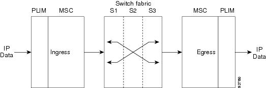
Data streams are received from the line side (ingress) through optic interfaces on the PLIM. The data streams terminate on the PLIMs. Frames and packets are mapped based on the Layer 2 (L2) headers.
The MSC converts packets to and from cells and provides a common interface between the routing system switch fabric and the assorted PLIMs. PLIMs provides the interface to user IP data. PLIMs perform Layer 1 and Layer 2 functions, such as framing, clock recovery, serialization and deserialization, channelization, and optical interfacing. Different PLIMs provide a range of optical interfaces, such as very-short-reach (VSR), intermediate-reach (IR), or long-reach (LR).
A PLIM eight-byte header is built for packets entering the fabric. The PLIM header includes the port number, the packet length, and some summarized layer-specific data. The L2 header is replaced with PLIM headers and the packet is passed to the MSC for feature applications and forwarding.
The transmit path is essentially the opposite of the receive path. Packets are received from the drop side (egress) from the MSC through the chassis midplane. The L2 header is based on the PLIM eight-byte header received from the MSC. The packet is then forwarded to appropriate Layer 1 devices for framing and transmission on the fiber.
A control interface on the PLIM is responsible for configuration; optic control and monitoring; performance monitoring; packet count; error-packet count and low-level operations of the card; such as PLIM card recognition; power up of the card; and voltage and temperature monitoring.
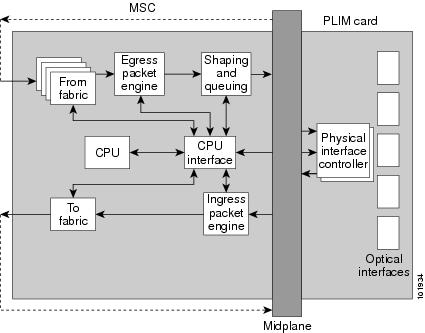
This is a simple block diagram of the major components of an MSC/PLIM pair. These components are described in the sections that follow. This diagram also applies to the FP and LSP line cards.
- PLIM Physical Interface Module on Ingress
- MSC Ingress Packet Engine
- MSC To Fabric Section and Queuing
- MSC From Fabric Section
- MSC Egress Packet Engine
- Shaping and Queuing Function
- PLIM Physical Interface Section on Egress
- MSC CPU and CPU Interface
PLIM Physical Interface Module on Ingress
As shown in the above figure, received data enters a PLIM from the physical optical interface. The data is routed to the physical interface controller, which provides the interface between the physical ports, and the Layer 3 function of the MSC. For received (ingress) data, the physical interface controller performs the following functions:
- Multiplexes the physical ports and transfers them to the ingress packet engine through the line card chassis midplane.
- Buffers incoming data, if necessary, to accommodate back-pressure from the packet engine.
- Provides Gigabit
Ethernet specific functions, such as:
- VLAN accounting and filtering database
- Mapping of VLAN subports
MSC Ingress Packet Engine
The ingress packet engine performs packet processing on the received data. It makes the forwarding decision and places the data into a rate-shaping queue in the “to fabric” section of the board. To perform Layer 3 forwarding, the packet engine performs the following functions:
- Classifies packets by protocol type and parses the appropriate headers on which to do the forwarding lookup on
- Performs an algorithm to determine the appropriate output interface to which to route the data
- Performs access control list filtering
- Maintains per-interface and per-protocol byte-and-packet statistics
- Maintains Netflow accounting
- Implements a flexible dual-bucket policing mechanism
MSC To Fabric Section and Queuing
The “to fabric” section of the board takes packets from the ingress packet engine, segments them into fabric cells, and distributes (sprays) the cells into the four planes of the switch fabric. Because each MSC has multiple connections per plane, the “to fabric” section distributes the cells over the links within a fabric plane. The chassis midplane provides the path between the “to fabric” section and the switch fabric (as shown by the dotted line in "MSC and PLIM Simple Block Diagram").
- The first level performs ingress shaping and queuing, with a rate-shaping set of queues that are normally used for input rate-shaping (that is, per input port or per subinterface within an input port), but can also be used for other purposes, such as to shape high-priority traffic.
- The second level consists of a set of destination queues where each destination queue maps to a destination MSC, plus a multicast destination.
Note that the flexible queues are programmable through the Cisco IOS XR software.
MSC From Fabric Section
The “from fabric” section of the board receives cells from the switch fabric and reassembles the cells into IP packets. This section of the card then places the IP packets in one of its 8-K egress queues, which helps the section adjust for the speed variations between the switch fabric and the egress packet engine. Egress queues are serviced using a modified deficit round-robin (MDRR) algorithm. The dotted line in "MSC and PLIM Simple Block Diagram" indicates the path from the midplane to the “from fabric” section.
MSC Egress Packet Engine
The transmit (egress) packet engine performs a lookup on the IP address or MPLS label of the egress packet based on the information in the ingress MSC buffer header and on additional information in its internal tables. The transmit (egress) packet engine performs transmit side features such as output committed access rate (CAR), access lists, DiffServ policing, MAC layer encapsulation, and so on.
Shaping and Queuing Function
The transmit packet engine sends the egress packet to the shaping and queuing function (shape and regulate queues function), which contains the output queues. Here the queues are mapped to ports and classes of service (CoS) within a port. Random early-detection algorithms perform active queue management to maintain low average queue occupancies and delays.
PLIM Physical Interface Section on Egress
On the transmit (egress) path, the physical interface controller provides the interface between the MSC and the physical ports on the PLIM. For the egress path, the controller performs the following functions:
- Support for the physical ports. Each physical interface controller can support up to four physical ports and there can be up to four physical interface controllers on a PLIM.
- Queuing for the ports
- Back-pressure signalling for the queues
- Dynamically shared buffer memory for each queue
- A loopback function where transmitted data can be looped back to the receive side
MSC CPU and CPU Interface
As shown in "MSC and PLIM Simple Block Diagram", the MSC contains a central processing unit (CPU) that performs these functions:
The CPU subsystem includes:
- A CPU chip
- A Layer 3 cache
- NVRAM
- A flash boot PROM
- A memory controller
- Memory, a dual in-line memory module (DIMM) socket, providing up to 2 GB of 133 MHz DDR SDRAM on the CRS-MSC, up to 2 GB of 166 MHz DDR SDRAM on the CRS-MSC-B, and up to 8GB of 533MHz DDR2 SDRAM on the CRS-MSC-140G.
The CPU interface provides the interface between the CPU subsystem and the other ASICs on the MSC and PLIM.
The MSC also contains a service processor (SP) module that provides:
- MSC and PLIM power-up sequencing
- Reset sequencing
- JTAG configuration
- Power monitoring
The SP, CPU subsystem, and CPU interface work together to perform housekeeping, communication, and control plane functions for the MSC. The SP controls card power up, environmental monitoring, and Ethernet communication with the line card chassis RPs. The CPU subsystem performs a number of control plane functions, including FIB download receive, local PLU and TLU management, statistics gathering and performance monitoring, and MSC ASIC management and fault-handling. The CPU interface drives high-speed communication ports to all ASICs on the MSC and PLIM. The CPU talks to the CPU interface through a high-speed bus attached to its memory controller.
Line Card Descriptions
The following figure shows a Cisco CRS routing system MSC. An MSC, FP, or LSP fits into any available MSC slot and connects directly to the midplane. All three versions of the MSC (CRS-MSC, CRS-MSC-B, and CRS-MSC-140G) are similar in appearance. The primary difference is the CRS-MSC-B and CRS-MSC-140G are a flat design, instead of modular.
The CRS-FP40 and CRS-FP140 cards are similar in appearance to the CRS-MSC-B.
The CRS-LSP card is similar in appearance to the CRS-FP140 card.
Note | The CRS-FP40 only supports the Cisco CRS 4-port 10-GE PLIM, Cisco CRS 42-port 1-GE PLIM, Cisco CRS 20-port 1-GE Flexible Interface Module, and 2x10GE WAN/LAN Flexible Interface Module. |
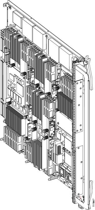
The main physical characteristics of the MSC, FP, and LSP cards are:
- Height—20.6 in.(52.3 cm)
- Depth—18.6 in. (47.2 cm)
- Width—1.8 in. (4.6 cm)
- Weight:
- CRS-MSC = 18.7 lb (8.5 kg)
- CRS-MSC-B = 12 lb (5.44 kg)
- CRS-FP40 = 12 lb (5.44 kg)
- CRS-MSC-140G = 14.75 lb (6.68 kg)
- CRS- FP140 = 14.75 lb (6.68 kg)
- CRS-LSP = 14.75 lb (6.68 kg)
- Power consumption:
- CRS-MSC = 375 W
- CRS-MSC-B = 300 W
- CRS-FP40 = 270 W
- CRS_MSC-140G = 446 W
- CRS- FP140 = 446 W
- CRS- LSP = 446 W
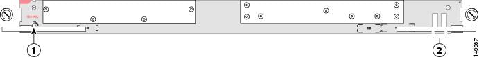
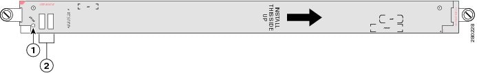
The following figure shows the CRS-MSC front panel.
|
1 |
Status LED |
2 |
Alphanumeric LEDs |
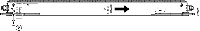
The following figure shows the CRS-MSC-B front panel.
|
1 |
Status LED |
2 |
Alphanumeric LEDs |
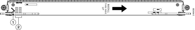
The following figure shows the CRS-MSC-140G front panel.
|
1 |
Status LED |
2 |
Alphanumeric LEDs |
The following figure shows the CRS-FP40 front panel.
|
1 |
Status LED |
2 |
Alphanumeric LEDs |
The following figure shows the CRS-FP140 front panel.
|
1 |
Status LED |
2 |
Alphanumeric LEDs |
The following figure shows the CRS-LSP front panel.

|
1 |
Status LED |
2 |
Alphanumeric LEDs |
Physical Layer Interface Modules
A physical layer interface module (PLIM) provides the packet interfaces for the routing system. Optic modules on the PLIM contain ports to which fiber-optic cables are connected. User data is received and transmitted through the PLIM ports, and converted between the optical signals (used in the network) and the electrical signals (used by line card chassis components).
Each PLIM is paired with a line card through the chassis midplane. The line card provides Layer 3 services for the user data, and the PLIM provides Layer 1 and Layer 2 services. A line card can be paired with different types of PLIMs to provide a variety of packet interfaces and port densities.
In the Cisco CRS 4-Slot Line Card Chassis, line cards and PLIMs are both installed in the front of the chassis, and mate through the chassis midplane. The chassis midplane enables you to remove and replace a line card without disconnecting the user cables on the PLIM.
You can mix and match PLIM types in the chassis.
 Warning | Because invisible radiation may be emitted from the aperture of the port when no fiber cable is connected, avoid exposure to radiation and do not stare into open apertures. Statement 125 |
Warning | Class 1 Laser Product. Statement 113 |
Warning | Class 1 LED product. Statement 126 |
Warning | For diverging beams, viewing the laser output with certain optical instruments within a distance of 100 mm may pose an eye hazard. For collimated beams, viewing the laser output with certain optical instruments designed for use at a distance may pose an eye hazard. Statement 282 |
Warning | Laser radiation. Do not view directly with optical instruments. Class 1M laser product. Statement 283 |
Various types of PLIM interfaces are available for the line card chassis. These interfaces are described in detail, in the following Cisco publications:
- Cisco CRS Carrier Routing System Packet-over-SONET/SDH Physical Layer Interface Module Installation Note
- Cisco CRS Carrier Routing System Gigabit Ethernet Physical Layer Interface Module Installation Note
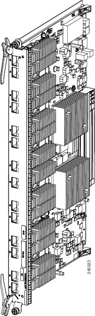
Here is an example of a typical PLIM (in this case, a 14-port 10-GE XFP PLIM. Other PLIMs are similar.
Chassis Cable Management
The line card chassis has cable-management features for the front of the chassis. These cable-management features consist of horizontal cable-management trays above the card cage. These trays have a special telescoping feature that allows them to be extended when the chassis is upgraded with higher-density cards. This extension feature also helps in installing the cables in the chassis.
See the Cisco CRS Carrier Routing System 4-Slot Line Card Chassis Installation Guide for detailed information about chassis cabling and cable management.
SPA Interface Processors and Shared Port Adapters
An optional interface solution (to PLIMs) is also available. SPA interface processors (SIPs) and shared port adapters (SPAs) can be installed instead of PLIMs. A SIP is a carrier card that is similar to a PLIM and inserts into a line card chassis slot and interconnects to an MSC like a PLIM. Unlike PLIMs, SIPs provide no network connectivity on their own.
A SPA is a modular type of port adapter that inserts into a subslot of a compatible SIP carrier card to provide network connectivity and increased interface port density. A SIP can hold one or more SPAs, depending on the SIP type and the SPA size. POS/SDH and Gigabit Ethernet SPAs are available. For complete SIP and SPA information, see the Cisco CRS Carrier Routing System SIP and SPA Hardware Installation Guide.
 Feedback