Cisco CRS Carrier Routing System 4-Slot Line Card Chassis System Description
Bias-Free Language
The documentation set for this product strives to use bias-free language. For the purposes of this documentation set, bias-free is defined as language that does not imply discrimination based on age, disability, gender, racial identity, ethnic identity, sexual orientation, socioeconomic status, and intersectionality. Exceptions may be present in the documentation due to language that is hardcoded in the user interfaces of the product software, language used based on RFP documentation, or language that is used by a referenced third-party product. Learn more about how Cisco is using Inclusive Language.
- Updated:
- February 12, 2017
Chapter: Chassis Cooling System
Chassis Cooling
System
This chapter describes the components that make up the cooling system of the line card chassis. The following sections are included:
Cooling System Overview
The cooling system dissipates the heat generated by the line card chassis and controls the temperature of chassis components. The cooling system has a redundant architecture that allows the chassis to continue operating with a single fan failure. See the Cooling System Redundancy section for more information.
The complete chassis cooling system includes:
- One fan tray (holds four fans and fan controller)
- Temperature sensors (on cards and modules throughout the chassis)
- Control software and logic
- An air filter and air inlet vent
- Impedance carriers for empty chassis slots
The power modules in the power shelf also have their own self-contained cooling fans and air filter.
All four fans in the fan tray operate as a group. So, if it is necessary to increase or decrease airflow, all of the fans in the tray increase or decrease their rotation speed together.
Thermal sensors (inlet, exhaust, and hot-spot) are located on the system boards throughout the chassis and are used to monitor temperature readings and identify when the system is not cooling properly.
Software running on several types of service processor (SP) modules is used to control the operation of the fans. These SP modules are connected by internal Ethernet to the system controller on the route processor (RP).
Chassis Airflow
The following figure shows how air moves through the line card chassis. The air inlet at the bottom front of the chassis pulls in ambient air and passes it through the card cage. Warm air is exhausted out the top rear of the chassis through the fans. An air filter above the power shelf filters the incoming air.
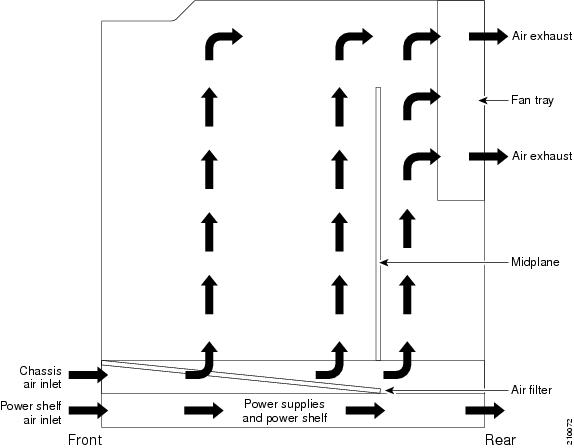
 Note | The chassis card cage has a maximum airflow of 880 cubic feet (24,919 liters) per minute. |
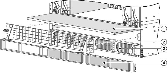
The chassis has a replaceable air filter mounted in the front of the chassis in a slide-out tray above the power shelf. The chassis air filter is shown in the following figure .
You should change the air filter as often as necessary. In a dirty environment, or when you start getting frequent temperature alarms, check the intake grills for debris and check the air filter to see if it needs to be replaced.
 Caution | See the Cisco CRS Carrier Routing System 4-Slot Line Card Chassis Installation Guide for the specific air filter replacement procedure. |
|
1 |
Chassis air filter |
3 |
Power shelf and power modules |
|
2 |
Air intake grille |
4 |
Power shelf air filter |
Cooling System Operation
The fan control software and related circuitry varies the fan speed signal to individual fans to control their speed. This increases or decreases the airflow needed to keep the system operating in a desired temperature range. The chassis cooling system uses multiple fan speeds to optimize cooling, acoustics, and power consumption.
At initial power up, the fans default to 4000 RPM. This provides airflow during system initialization and software boot, and ensures that there is adequate cooling for the chassis in case the software hangs during boot. The fan control software initializes after the routing system software boots, which can take three to five minutes. The fan control software then adjusts the fan speeds appropriately, up to 7500 RPM.
During normal operation, the chassis averages the temperatures reported by inlet temperature sensors. To determine the appropriate fan speed for the current temperature, the fan control software compares the averaged inlet temperature to a lookup table that lists the optimal fan speed for each temperature. The software then sets the fan speed to the appropriate value for the current temperature. To avoid dynamic oscillation of the fan speed, the fan speed control is regulated in discrete steps.
Note | When there are no active alarms or failures, the fan control software checks temperature sensors every two to three minutes. |
Thermal Alarms
Local thermal sensors (on individual cards) monitor temperatures and generate a thermal alarm when the cooling system is not cooling properly. A temperature sensor might trip in response to elevated ambient air temperature, a clogged air filter or other airflow blockage, or a combination of these causes. A fan failure causes a fault message, but if no thermal sensors have tripped, the fan control remains unchanged.
When a thermal sensor reports a thermal alarm, the sensor passes the fault condition to its local service processor (SP), which then notifies the system controller on the route processor (RP). The system controller passes the fault condition to the SP on the fan controller. The fan control software then takes appropriate action to resolve the fault.
When a thermal sensor trips, the fan control software tries to resolve the problem (for example, by increasing fan speed). The software performs a series of steps to prevent chassis components from getting anywhere near reliability-reducing, chip-destroying temperatures. If the fault continues, the software shuts down the card or module to prevent permanent damage to the components.
Cooling System Redundancy
The redundant architecture of the cooling system allows the cooling system to continue operating even when certain components fail. The cooling system can withstand the failure of any one of the following components and still continue to properly cool the line card chassis:
- Any one of the four fans in the fan tray
- One or two of the four AC rectifiers in the AC power shelf
- One or two of the four DC power supplies in the DC power shelf
Note | When a cooling system component fails, it should be replaced within 24 hours. |
Fan Tray
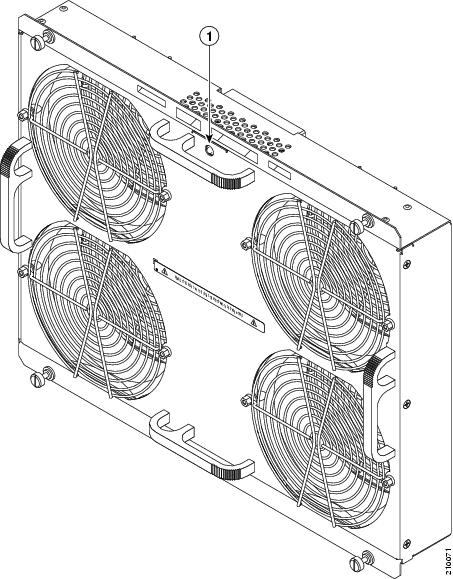
The following figure shows a fan tray, which plugs into the rear of the chassis.
|
1 |
Status LED |
The fan tray contains the following components:
- Four fans—Each fan uses –36 to –72 VDC as its input power. The fans operate in the range of 3500 to 7500 RPM.
Note | The fan speed range limits listed in this document are nominal. These numbers have a tolerance of plus or minus 10 percent. |
- Fan controller—The board terminates signals to and from the fans, filters common-mode noise, and contains tracking and indicator parts. The fan controller is not user accessible or field replaceable.
- Status LED—The LED
indicates the following:
- Green—The fan tray is operating normally.
- Yellow—The fan tray or a fan has experienced a failure and should be replaced.
- Off—The RP has not booted, the LED is faulty, or no power is being received.
The fan tray has the following physical characteristics:
- Height—13.7 in. (34.7 cm)
- Width—17.4 in. (44.1 cm)
- Depth—3.7 in. (9.3 cm)—Includes rear connector and front handles
- Weight—16 lb (7.2 kg)
 Feedback