Cisco CRS Carrier Routing System 8-Slot Line Card Chassis System Description
Bias-Free Language
The documentation set for this product strives to use bias-free language. For the purposes of this documentation set, bias-free is defined as language that does not imply discrimination based on age, disability, gender, racial identity, ethnic identity, sexual orientation, socioeconomic status, and intersectionality. Exceptions may be present in the documentation due to language that is hardcoded in the user interfaces of the product software, language used based on RFP documentation, or language that is used by a referenced third-party product. Learn more about how Cisco is using Inclusive Language.
This chapter describes the power systems of the Cisco CRS 8-Slot Line Card Chassis. It contains the following topics:
Power Systems Overview
There are two options for power systems:
Fixed configuration power system—consists of two power distribution units (PDUs) and either DC power entry modules (PEMs)
or AC rectifiers. The AC version requires 3-phase AC-Delta or AC-Wye input power to the PDU. The PDU distributes facility
power to the AC rectifier or DC PEM, which in turn provides processed power to the chassis. The fixed configuration power
system includes SNMP MIBS and XML support.
Note
In a fixed configuration AC or DC power system, PDU refers to the power component that connects to the AC rectifier or DC
PEM.
Modular configuration power system—consists of two power shelves and either AC or DC power modules (PMs). However, unlike
the fixed configuration power system, the AC version of the modular configuration power system requires single-phase AC input
power to power the shelves. If you have 3-phase AC-Delta or AC-Wye at your equipment, a Cisco CRS PDU will be required to
convert 3-phase AC input power to single-phase AC input power for the power shelf. At the shelf level, the power system provides
2N redundancy; the PMs themselves provide load-share redundancy. The modular configuration power system also includes SNMP
MIBs and XML support.
Note
In a modular configuration AC power system, PDU refers to the Cisco CRS PDU that converts 3-phase AC-Wye or AC-Delta input
power to single-phase AC input power for the modular configuration AC power shelf. For further information, see the
Cisco CRS 3-Phase AC Power Distribution Unit Installation Guide
.
Power components are not interchangeable between the fixed and modular configuration power system.
Power Component Information Common to Two Types of Power System
Basic Chassis Power Details
The Cisco CRS 8-slot line card chassis can be configured with either a DC-input power system or an AC-input power system.
The chassis power system provides the necessary power for chassis components. Input power availability is site dependent and
may be DC, AC Delta, or AC Wye.
A fixed configuration AC PDU connects to an AC rectifier, while a fixed configuration DC PDU connects to a DC PEM. A modular
configuration AC power shelf houses up to 3 AC PMs, while a modular configuration DC power shelf houses up to 4 DC PMs. It
is required that you use only one type of power shelf in a chassis at a time.
Note
In a modular configuration power system, both AC and DC power supplies are referred to as power modules (PMs).
Note
This unit might have more than one power module connection. All connections must be removed to de-energize the unit.Statement1028
Power System-Fixed Configuration
Three types of PDUs exist for fixed configuration power system:
AC Wye PDU
AC Delta PDU
DC PDU
The AC PDU connects to the AC rectifier, while the DC PDU connects to the DC PEM. Although there are differences among the
different PDU types (AC Wye, AC Delta, and DC), they are installed in the same manner.
Fixed configuration power system consists of two power distribution units (PDUs) and either DC power entry modules (PEMs)
or AC rectifiers. The AC version requires 3-phase AC-Delta or AC-Wye input power to the PDU. The PDU distributes facility
power to the AC rectifier or DC PEM, which in turn provides processed power to the chassis. The fixed configuration power
system includes SNMP MIBS and XML support.
Note
In a fixed configuration AC or DC power system, PDU refers to the power component that connects to the AC rectifier or DC
PEM.
Modular configuration power system consists of two power shelves and either AC or DC power modules (PMs). However, unlike
the fixed configuration power system, the AC version of the modular configuration power system requires single-phase AC input
power to power the shelves. If you have 3-phase AC-Delta or AC-Wye at your equipment, a Cisco CRS PDU will be required to
convert 3-phase AC input power to single-phase AC input power for the power shelf. At the shelf level, the power system provides
2N redundancy; the PMs themselves provide load-share redundancy.
Note
In a modular configuration AC power system, PDU refers to the Cisco CRS PDU that converts 3-phase AC-Wye or AC-Delta input
power to single-phase AC input power for the modular configuration AC power shelf. For further information, refer to Cisco
CRS 3-Phase AC Power Distribution Unit Installation Guide.
Caution
Use only one type of modular configuration power shelf—AC or DC—and its mating AC or DC PMs in a chassis at one time.
Precautions and Recommendations
Follow these precautions and recommendations when planning power connections to the router:
For the fixed configuration power system, although PDUs may be installed or removed without powering down the system, for
safety purposes we recommend that you power down the system before you install or remove a PDU.
For the modular configuration power system, although power shelves may be installed or removed without powering down the system,
for safety purposes we recommend that you power down the system before you install or remove a power shelf.
Grounding Guidelines
The router chassis has safety earth ground connections in conjunction with the power cabling to the fixed configuration PDUs.
Modular configuration supports chassis grounding only. The chassis allows you to connect the central office ground system
or interior equipment ground system to the bonding and grounding receptacles on the router chassis, when either a fixed or
modular configuration power system is installed.
Each side of the chassis has one pair of threaded ground studs located on the inside of the chassis and two sets of grounding
receptacles located on the outside of the chassis. These ground points are also called the network equipment building system
(NEBS) bonding and grounding points.
Note
These bonding and grounding receptacles satisfy the Telcordia NEBS requirements for bonding and grounding connections.
This figure shows six chassis grounding points that are provided at the rear (MSC) side of the chassis.
Figure 1. NEBS Bonding and Grounding Points (Rear of Chassis) - Fixed Configuration AC Power Shown
1
NEBS bonding and grounding points (inside chassis)
2
NEBS bonding and grounding points (outside chassis)
Caution
Do not remove the chassis ground wire unless the chassis is being replaced.
Each DC powered chassis contains two fixed configuration PDUs or two modular configuration power shelves for 2N redundancy.
In the fixed configuration power system, each PDU accepts one DC PEM for 2N redundancy. The PDUs and PEMs are field replaceable.
The PDUs contain the input power connectors.
In the modular configuration power system, each power shelf accepts up to four PMs. The power shelves and PMs are field replaceable.
The power shelves contain the input power connectors.
Note
Depending on the hardware deployed at your site, your system may not consume the maximum power supplied by the power system.
AC Power Systems
Each AC powered chassis contains two AC power shelves for 2N redundancy. The shelves contain the input power connectors.
In the fixed configuration power system, each PDU accepts one AC power rectifier. The PDUs and AC power rectifiers are field
replaceable.
In the modular configuration power system, each power shelf can contain up to three AC PMs. The power shelves and the AC PMs
are field replaceable. See Modular Configuration Power System.
Note
Depending on the hardware deployed at your site, your system may not consume the maximum power supplied by the power system.
Installing a Fixed Configuration Power System
This section describes the fixed configuration power system and contains the following topics:
Fixed Power Configuration Overview
This section describes the Cisco CRS 8-slot fixed power configuration system.
Caution
Use only one type of fixed configuration PDU—AC Wye, AC Delta, or DC—and its mating AC rectifier or DC PEM in a chassis at
one time.
The Cisco CRS 8-slot line card chassis DC power system provides 7,500 watts to power the chassis. Each DC PDU is connected
to three pairs of DC power feeds and powers a single DC PEM. Input DC power enters the PDU and is passed to the PEM, which
provides power to the components in the chassis.
Each DC PEM has its own circuit breaker.
The fixed configuration power system distributes power in power zones.
The DC PDUs and DC PEMs are field replaceable.
Fixed Configuration
Power Architecture
Cisco CRS 8-Slot
chassis AC and DC fixed configuration power systems use A and B power supplies
to provide reliable power to all chassis components. In the fixed configuration
power system, each PDU accepts one DC PEM for 2N redundancy. The PDUs and PEMs
are field replaceable. The PDUs contain the input power connectors.
The chassis requires
8.0 kW of DC input power and 8.75 kW of AC input power from the building
supply.
AC or DC input power
enters the chassis through the A and B power supplies and is distributed to the
A or B power bus. Both buses distribute power through the midplane to the MSC,
PLIM, switch fabric, and RP card slots. See the figure titled
CRS 8-Slot Line Card Chassis Power Distribution - Fixed DC
Configuration in the
Fixed Configuration DC Power Distribution Unit section for
the 8-slot chassis power routing distribution for a fixed DC configuration and
the figure titled
CRS 8-Slot Chassis AC Delta Power Distribution - Fixed
Configuration in the
Fixed Configuration AC Delta Power section for the power
routing distribution for a fixed AC configuration.
The A power module supplies –54.5 VDC
to the A bus.
The B power module supplies –54.5 VDC
to the B bus.
Because chassis
components are powered by both A and B power inputs, the line card chassis can
continue to operate normally if:
One AC rectifier
or DC PEM fails.
One input power (A
or B) fails.
One bus fails.
One PDU fails.
It takes two failures
for the system to be degraded. In addition, the failures must occur in both the
A and B sides of the power architecture and affect the same power zone for the
degradation to occur.
Individual chassis
components have power-related devices (OR-ing diodes, inrush control circuits,
and EMI filters) that are part of the chassis power architecture. These
power-related devices form part of the dual power source (A and B bus)
architecture, and enable online insertion and removal (OIR) of the components,
also called
hot swapping .
Fixed Configuration Chassis Power Zones
The AC or DC power system distributes power in the chassis through three power zones, which provide power redundancy and reliability.
Each power zone receives power from both power supplies, which ensures that each zone can operate in case of one power module
failure.
This image
shows the three power zones in the chassis. The table below the figure identifies the power redundancy connection for the
fan trays.
Figure 2. Cisco CRS 8-Slot Line Card Chassis Power Zones
Each fan tray—the upper fan tray (Fan 0) or the lower fan tray (Fan 1)—is powered by both PS A and PS B to have power redundancy
for the fan tray. In addition, both fan trays receive power from both Power Zones 1 and 3 for redundancy. Both fan trays are
monitored by RP0 and RP1 shelf controllers.
Any types of cards can be installed in a power zone.
Fixed Configuration DC Power
The Cisco CRS 8-slot line card chassis DC power system provides 7,500 watts to power the chassis. Each DC PDU is connected
to three pairs of DC power feeds and powers a single DC PEM. Input DC power enters the PDU and is passed to the PEM, which
provides power to the components in the chassis.
Each DC PEM has its own circuit breaker.
The fixed configuration power system distributes power in power zones.
The DC PDUs and DC PEMs are field replaceable.
Unlike the Cisco CRS 16-slot line card chassis, the Cisco CRS 8-slot line card chassis does not contain an alarm module. A
microprocessor in the DC PEM monitors the status of each DC PEM. The microprocessor communicates with the system controller
on the route processor (RP) card. LEDs on the front panel of the RP card indicate active alarm conditions.
The DC PDU is shipped with a plastic safety cover over the input terminal block, as shown in the figure below. This safety
cover has two parts, each part held on to the PDU with a Phillips screw. We recommend removing the safety cover only when
wiring and unwiring the chassis. The safety cover is slotted in such a way that the wires can only come out on the bottom
portion of the cover.
Figure 3. Fixed Configuration DC PDU With Plastic Safety Cover
1
Each set of cables (RTN and –48/–60 VDC) is a single VDC input.
Each PDU requires three DC inputs of –48/–60 VDC (nominal), 60 A service. The PDU accepts input DC power in the range –40.5
to –75 VDC, and has three sets of double-stud terminals (-48/-60 VDC Lines and -48/-60 VDC Returns) for connecting to the
VDC inputs.
Each DC PDU should be connected to a different central office DC power source:
One PDU should be connected to three –48/–60 VDC “A” buses.
Other PDU should be connected to three –48/–60 VDC “B” buses.
If DC power to a PDU fails, the other PDU provides enough power for the chassis. This 2N power redundancy enables the routing
system to operate in spite of single power failure.
For DC power cables, we recommend that you use commensurately rated, high-strand-count copper wire cable, based on local electrical
codes. These wires are not available from Cisco Systems; they are available from any commercial vendor. DC power cables must
be terminated by cable lugs at the power shelf end.
This table lists the fixed configuration DC power components and PIDs for the Cisco CRS 8-Slot Line Card Chassis.
Table 3. Fixed Configuration DC Power Components
Power Component
DC PDU
CRS-8-LCC-PDU-DC(=)
Cisco CRS DC power distribution unit(two required for each chassis)
DC PEM
CRS-8-DC-PEM(=)
Cisco CRS DC PEM1(two required for each chassis, one for each PDU)
Power module filter
CRS-8-PWR-FILTER(=)
Filters (five per pack) for AC rectifier and DC PEM
A DC power distribution unit (PDU) contains one DC input terminal block with 6 poles of two row M6 studs mating with industry
standard two-hole compression lugs on 5/8-inch centers, one ground blade connector and one output connector mating with the
DC PEM. One DC PDU requires three independent nominal -48/-60 VDC, 60 A input services.
One DC PDU requires six 45° angle, industry standard, 2-hole compression lugs with holes on 5/8- inch centers for three pairs
(three -48/-60 VDC inputs and three returns) of DC input connections.
This figure illustrates the 8-slot chassis power routing distribution for a fixed DC configuration.
Figure 4. CRS 8-Slot Line Card Chassis Power Distribution - Fixed DC Configuration
Fixed Configuration DC Power Entry Module
The DC power entry module, shown in DC PEM—Front View figure, processes input power from the DC PDU and passes the power to the system chassis. DC PEMs are field-replaceable.
Three -48/-60 VDC inputs enter the DC PEM at the rear of the PEM through a connector on the DC PDU. The PEM performs inrush
current limiting, EMI filtering, surge protection, and over voltage protection to process the power before it exits the PEM
and is distributed to the chassis midplane.
Each DC PEM has self-contained cooling fans that draw air through the module.
This figure shows the front of the DC PEM. The yellow power switch on the front top left corner can be pushed or pulled to
turn the power on or off, respectively.
Figure 5. DC PEM—Front View
1
Power switch
3
Handle
2
Module air filter
4
Captive screws
A microprocessor in the DC PEM monitors the status of each DC PEM. The microprocessor communicates with the system controller
on the route processor (RP) card. The microprocessor circuitry monitors the following DC PEM fault and alarm conditions:
Fault: Indicates a failure in an DC PEM, such as failed bias supply, or over temperature. It includes a warning that the DC output
voltage is outside the allowable output range.
DCInputFail: Indicates that the DC input voltage is out of range.
CircuitBreakerTrip: Indicates that the DC PEM circuit breaker has tripped.
OverTemperature: Indicates that the DC PEM has exceeded the maximum allowable operating temperature.
DCPEMPresent: Indicates that the DC PEM is present and seated properly in the system chassis.
VoltageandCurrentMonitorsignals(Vmon,Imon): Indicates how much output voltage and current are provided by the DC PEM.
Each DC PEM contains an ID EEPROM that stores information used by the control software (for example, part number, serial number,
assembly deviation, special configurations, test history, and field traceability data).
Fixed Configuration DC PEM Indicators
Each DC PEM has power and status indicators. The DC PEM indicators receive power from both DC PEMs; therefore, the indicators
are operational even when the DC PEM is not powered from its input voltage.
This table lists DC PEM status indicators and their functions.
Table 4. DC PEM Status Indicators
Name
Color
Function
PWR OK
Green
The DC PEM is operating normally with power.
FAULT
Yellow
A fault has been detected in the DC PEM.
DC INPUT FAIL
Yellow
DC input is out of range or is not being provided to the DC PEM.
OT
Yellow
The DC PEM is overheated and it has been shut down.
BREAKER TRIP
Yellow
The input circuit breaker is off (in the off position).
This table lists DC PEM LED readings during failure conditions.
Table 5. DC PEM LED Conditions
Condition
PWR OK LED
Fault LED
DC Input Fail LED
OT LED
Breaker Trip LED
No fault (power is on)
On
Off
Off
Off
Off
Failed DC input power
Off
Off
On
Off
Off
Overheated temperature
Off
On
Off
On
Off
Tripped breaker
Off
Off
Off
Off
On
Fixed Configuration AC Power
An AC-powered Cisco CRS 8-slot line card chassis contains two AC power distribution units (PDUs) and two AC rectifier modules.
Each AC PDU is connected to a 3-phase (200 to 240) input VAC power source and connects to a single 7500-watt AC rectifier
module that is field replaceable. Each AC rectifier module converts input AC power to the 54.5 VDC used by the chassis. Each
rectifier has its own circuit breaker.
To provide 2N power redundancy for the chassis, each PDU and AC rectifier pair is connected to a different AC power source.
During normal operation when both power sources are operational, both PDUs and rectifiers function together to power the chassis.
However, if a power source fails, the other power source provides the other PDU and rectifier pair with enough input power
to power the chassis. This 2N power redundancy enables the routing system to operate despite the power failure.
Two versions of the AC PDU are available to accommodate AC input power in either the Delta or Wye (see Figure 1 for fixed AC Wye PDU) configuration. Each PDU has a different Cisco part number. The PDUs are shipped with AC power cords
that are 14 feet (4.3 m) long.
Unlike the Cisco CRS 16-slot line card chassis, the Cisco CRS 8-slot line card chassis does not contain an alarm module. A
microprocessor in the AC rectifier monitors the status of each AC rectifier. The microprocessor communicates with the system
controller on the RP card. LEDs on the front panel of the RP card indicate active alarm conditions.
The AC PDUs have the following input VAC power requirements:
AC Wye input: 3-phase, 200 to 240 VAC nominal (phase-to-neutral), 50 to 60 Hz, 16 A (International) or 20 A (North America).
The PDU is rated for 14-amp service, and accepts AC input of 16 or 20 A.
The Wye power cord has a 5-pin IEC 60309 plug that is rated for 400 VAC, 16 or 20 A, (3W + N + PE). The power cord plugs into
a similarly rated IEC 60309 receptacle.
AC Delta input: 3-phase, 200 to 240 VAC nominal (phase-to-phase), 50 to 60 Hz, 30 A. The PDU is rated for 24-amp service,
and accepts AC input of 30 A.
The Delta power cord has a 4-pin NEMA L15-30P plug that is rated for 250 VAC, 30 A (3W + PE). The power cord plugs into a
similarly rated NEMA L15-30R locking-type receptacle.
Figure 6. Fixed Configuration AC Wye PDU
This table lists the AC power components and PIDs for the Cisco CRS 8-Slot Line Card Chassis.
Table 6. Fixed Configuration AC Power Components
AC Delta Power Component
AC Delta PDU
CRS-8-LCC-PDU-ACD(=)
Cisco CRS AC Delta power distribution unit(two required for each chassis)
AC rectifier module
CRS-8-AC-RECT(=)
Cisco CRS AC rectifier module(two required for each chassis, one for each PDU)
AC WYE Power Component
AC Wye PDU
CRS-8-LCC-PDU-ACW(=)
Cisco CRS AC Wye power distribution unit(two required for each chassis)
AC rectifier module
CRS-8-AC-RECT(=)
Cisco CRS AC rectifier module(two required for each chassis, one for each PDU)
Power module filter
CRS-8-PWR-FILTER(=)
Filters (five per pack) for AC rectifier and DC PEM
Note
For a complete list of CRS 8-slot chassis power specifications, see
Appendix 1, “Technical Specifications.”
Fixed Configuration AC Delta Power
The AC Delta PDU contains the AC cable assembly with AC plug, EMI filter, and power distribution connections and wiring.
This figure shows the 8-slot chassis power routing distribution for a fixed AC configuration.
Figure 7. CRS 8-Slot Chassis AC Delta Power Distribution - Fixed Configuration-
This figure shows wiring for the AC Delta PDU.
Figure 8. AC Delta Power Wiring
Fixed Configuration AC Wye Power
This figure shows wiring for the AC Wye PDU.
Figure 9. AC Wye Power Wiring
Fixed Configuration AC Rectifier
The AC rectifier is an AC power module that converts input AC power into the DC power necessary to power chassis components.
Note
The same AC rectifier is used with the AC Delta and AC Wye PDUs.
The rectifier takes AC input power from the PDU, rectifies the AC into DC, provides filtering and control circuitry, provides
status signaling, and passes the regulated and isolated DC power to the chassis midplane. Each AC rectifier has self-contained
cooling fans that draw air through the module.
This figure shows the front of the AC power rectifier. The yellow power switch is on the front top left corner of the rectifier.
The switch can be pushed or pulled to turn the power on or off, respectively.
Figure 10. AC Power Rectifier—Front View
1
Power switch
3
Handle
2
Module air filter
4
Captive screws
After the power enters the AC rectifier, internal circuits rectify the AC into DC, filter and regulate it. The conversion
from AC to DC is done in two stages:
The first stage is for power factor correction (PFC). The PFC process converts the AC to regulated primary DC. The PFC maintains
the AC input current to be sinusoidal and in-phase with the AC input. The result is near unity power factor.
The second stage is DC-to-DC conversion. The DC-to-DC process converts regulated primary side DC power to isolated –54.5 VDC
secondary power.
A microprocessor in the AC rectifier monitors the status of each AC rectifier. The microprocessor communicates with the system
controller on the route processor (RP) card. The microprocessor circuitry monitors the following AC rectifier fault and alarm
conditions:
Fault: Indicates a failure in an AC rectifier, such as failed bias supply, over temperature or current limit. It includes a warning
that the DC output is out of the allowable output range.
ACInputFail: Indicates that the AC input voltage is out of range.
CircuitBreakerTrip: Indicates that the AC rectifier circuit breaker has tripped.
OverTemperature: Indicates that the AC rectifier has exceeded the maximum allowable operating temperature.
ACRectifierPresent: Indicates that the rectifier is present and seated properly in the power shelf.
VoltageandCurrentMonitorsignals(Vmon,Imon): Indicate how much output voltages and currents are provided by the AC rectifier.
Each AC rectifier contains an ID EEPROM that stores information used by control software (for example, part number, serial
number, assembly deviation, special configurations, test history, and field traceability data).
Fixed Configuration AC Rectifier Status Indicators
Each AC rectifier has power and status indicators. The AC rectifier status indicators receive power from both AC power rectifiers;
therefore, the status indicators are operational even when the AC rectifier is not powered from its input voltage.
Table 1 lists the AC rectifier status indicators and their functions.
Table 7. AC Rectifier Status Indicators
Name
Color
Function
PWR OK
Green
The AC rectifier is operating normally with power.
FAULT
Yellow
A fault has been detected in the AC rectifier.
AC INPUT FAIL
Yellow
AC input is out of range or is not being provided to the AC rectifier.
OT
Yellow
The AC rectifier is overheated and it has been shut down.
BREAKER TRIP
Yellow
The input circuit breaker is off (in the off position).
ILIM
Yellow
The AC rectifier is operating in a current limiting condition.
Table 2 lists the LED readings during failure conditions
Table 8. AC Rectifier LED Conditions
Condition
PWR OK LED
Fault LED
AC Input Fail LED
OT LED
Breaker Trip LED
ILIM LED
No fault (power is on)
On
Off
Off
Off
Off
Off
Failed AC input power
Off
Off
On
Off
Off
Off
Overheated temperature
Off
On
Off
On
Off
Off
Tripped breaker
Off
Off
Off
Off
On
Off
Current limit
Off
On
Off
Off
Off
On
Modular Configuration Power System
This section describes the modular configuration power system and contains the following topics:
Modular Power Configuration Overview
This section describes the CRS 8-slot chassis modular configuration power system. The modular configuration power solution
is configurable. It includes the following components:
Two (redundant) AC or DC power shelves
Up to three AC power modules or four DC power modules per power shelf
Each DC power module provides 2100 Watts, with potential growth up to 8.4KW DC power per power shelf
Each AC power module provides 3000 Watts, with potential growth up to 9KW DC power per power shelf
Note
The default modular configuration power system may not ship with the maximum number of power modules configured. Additional
power modules can be added at any time, depending on the system’s power requirements.
The figures show an AC modular power module for the Cisco CRS 8-slot chassis.
Figure 11. Modular Configuration AC Power Shelf —Front View
Figure 12. Modular Configuration AC Power Shelf—Rear View
The figures show a front and rear view of a DC modular power shelf for the Cisco CRS 8-slot chassis.
Figure 13. Modular Configuration DC Power Shelf —Front View
Figure 14. Modular Configuration DC Power Shelf —Rear View
Modular Configuration Power Architecture
In the modular configuration power system, each power shelf accepts up to four PMs. The power shelves and PMs are field replaceable.
The power shelves contain the input power connectors.
Note
Depending on the hardware deployed at your site, your system may not consume the maximum power supplied by the power system.
The modular configuration power module provides the following features:
AC or DC power shelf redundancy
PM load-share redundancy
Elimination of power zone restriction, while maintaining zone protection
Capacity for future growth
The modular AC and DC power systems use A and B power shelves to provide reliable, 2N redundant power to all chassis components.
All power modules in the modular power shelf power all zones. In addition, the modular power supplies work in parallel with
each other, and they can monitor power consumption, performance, analysis, and power management concurrently.
Unlike the Cisco CRS 16-slot line card chassis, the power shelf on the Cisco CRS 8-slot line card chassis does not contain
an alarm module. Instead, alarm functionality is integrated into the Route Processor (RP). The DC power module monitors power
module status and processes alarm functions. The AC or DC power module distributes power and passes power module status signals
to the system. Each power module has its own integrated fuse to protect the system, and each power module is plugged into
its own power outlet.
The Cisco CRS 8-Slot Line Card Chassis requires 8.0 kW of DC input power and 8.75 kW of AC input power from the building supply.
Modular Configuration DC Power
The Cisco CRS 8-slot line card chassis modular configuration DC power system can provide up to 8,400 W to power the line card
chassis. The modular configuration DC power system uses A and B power shelves to provide reliable, 2N redundant power to all
chassis components.
Note
Depending on the hardware deployed at your site, your system may not consume the maximum power supplied by the power system.
If DC power to one modular configuration power shelf fails, the other power shelf provides enough power for the chassis. This
2N power redundancy enables the routing system to operate in spite of single power failure.
This table summarizes the DC power system specifications for the Cisco CRS 8-Slot Line Card Chassis.
Table 9. DC Power System Specifications
DC Power Component
Specifications
Power Shelf
Two DC power shelves
DC Power Shelf: Supports up to four DC power modules
Power Redundancy
Two DC Power Shelves each containing up to four DC power modules—2N redundancy
DC Input
Required input current is as follows:
50 amps at –48 VDC nominal input voltage.
40 amps at –60 VDC nominal input voltage
60 amps at low input voltage (–40 VDC)
Required lugs: 45° angled industry standard 2-hole compression lugs with holes on 5/8- inch centers (for example, for AWG
no. 2 wire: Panduit part number LCC2-14AH-Q or equivalent).
Ground Lug
Industry standard 2-hole compression lug with holes on 5/8- inch centers (Panduit part number LCD6-14A-L, or equivalent)
This figure shows the 8-slot chassis power routing distribution for a modular DC configuration.
Figure 15. CRS 8-Slot Chassis Power Distribution- Modular DC Configuration
Modular Configuration DC Power Shelf
The DC modular configuration power shelf is the enclosure that houses the DC power modules and power distribution connections
and wiring. The power shelf installs in the Cisco CRS 8-slot line card chassis from the front and plugs into the chassis power
interface connector panel.
Each modular configuration DC power shelf requires up to four DC input feeds of either –48 VDC (nominal), 50 A or –60 VDC
(nominal), 40 A. The power shelf accepts input DC power in the range –40 to –72 VDC. Each terminal consists of two M6 threaded
studs, 0.6 inches long, and centered 0.625 inches apart. The terminals have a safety cover.
Each DC power shelf supports up to four power modules, and accepts one 60 A battery feed per power module. Input DC power
enters the power shelf and is processed by the power modules before being distributed to the chassis midplane. The power modules
perform inrush current limiting, EMI filtering, surge protection, and circuit isolation on the input DC power, and then distribute
the power via the internal bus bar in the chassis midplane.
Modular Configuration DC Power Module
Each DC power module provides 2100 Watts. The DC power module, shown in this figure passes the power via the internal bus
bar to the system and is similar to the AC power module. Power modules are field-replaceable.
Figure 16. Modular Configuration DC Power Module .
Two –48/–60 VDC inputs enter the power module at the rear of the power shelf, and exits the power module and is distributed
to the chassis midplane.
Unlike the Cisco CRS 16-slot line card chassis, the power shelf on the Cisco CRS 8-slot line card chassis does not contain
an alarm module. The DC power module monitors power module status and processes alarm functions. A microprocessor in the DC
power module monitors the status of each DC power module. The microprocessor communicates with the system controller on the
route processor (RP) card. The microprocessor circuitry monitors the following DC power module fault and alarm conditions:
Fault: Indicates a failure in an DC power module, such as failed bias supply, or over temperature. It includes a warning that the
DC output voltage is outside the allowable output range.
DCInputFail: Indicates that the DC input voltage is out of range.
OverTemperature: Indicates that the DC power module has exceeded the maximum allowable operating temperature.
DCPowerModulePresent: Indicates that the power module is present and seated properly in the system chassis.
VoltageandCurrentMonitorsignals(Vmon,Imon): Indicates how much output voltage and current are provided by the DC power module.
Each DC power module contains an ID EEPROM that stores information used by the control software (for example, part number,
serial number, assembly deviation, special configurations, test history, and field traceability data).
Modular Configuration DC Power Module Indicators
Each DC power module has power and status indicators. The DC power module indicators receive power from both DC power modules;
therefore, the indicators are operational even when the DC power module is not powered from its input voltage. The following
three LED status indicators are located on the front of each DC power module:
Input OK - Green
Output OK - Green
Internal Fault - Red
The power module LED status indicators are not visible when the front grille is installed.
Table 1 lists the power module status indicators and their functions.
Table 10. Power Module Status Indicators
Name
Color
Function
Input OK
Green
Input OK LED turns on continuously when input voltage is present and within the regulation range.
Input OK LED flashes when input voltage is present but not within the regulation range.
Input OK LED is off when input voltage is not present.
Input OK LED flashes when hot-unplugging the power module from the power shelf to indicate that there is energy in the power
module until the input bulk capacitor is completely discharged or the housekeeping circuit is shut down.
Output OK
Green
Output OK LED turns on continuously when power module output voltage is on.
Output OK LED flashes when power module output voltage is in a power limit or an overcurrent situation.
Internal Fault
Red
Internal Fault LED turns on continuously when there is an internal fault in the power module.
The Internal Fault LED on the DC power module is turned on continuously to indicate that one or more of the following internal
faults is detected inside the power module:
5V out of range
Output Stage OT
Fan Fault
OR-ing fault (Output voltage less than bus voltage)
OC shutdown
OT shutdown
OV shutdown
Input stage OT
Fault induced shutdown occurred
Thermal sensor fault
Vout out of range
Boost Vbulk fault
Once all of the faults have been removed and the power module is operating normally, the Internal Fault LED is turned off.
Modular Configuration AC Power
The Cisco CRS 8-slot line card chassis modular configuration AC power system can provide up to 9,000 W to power the line card
chassis.
Note
Depending on the hardware deployed at your site, your system may not consume the maximum power supplied by the power system.
The modular configuration power system provides the following features:
AC power shelf redundancy
PM load-share redundancy
Elimination of power zone distribution, while maintaining zone protection
Capacity for future growth
The modular configuration AC power systems use A and B power shelves to provide reliable, 2N redundant power to all chassis
components.
The Cisco CRS 8-slot line card chassis does not contain an alarm module. The AC PM monitors PM status and processes alarm
functions. The AC PM distributes power and passes PM status signals to the system. Each PM has its own integrated fuse to
protect the system, and each PM is plugged into its own power outlet. Alarms are processed through the RP. LEDs on the front
panel of the RP indicate active alarm conditions.
Unlike the fixed configuration AC power system, which requires 3-phase AC Delta or AC Wye input power, the modular configuration
AC power system requires single-phase AC input power. If you have 3-phase AC Delta or AC Wye at your equipment, a Cisco CRS PDU will be required to convert 3-phase AC input power to single-phase AC input power for the power shelf .
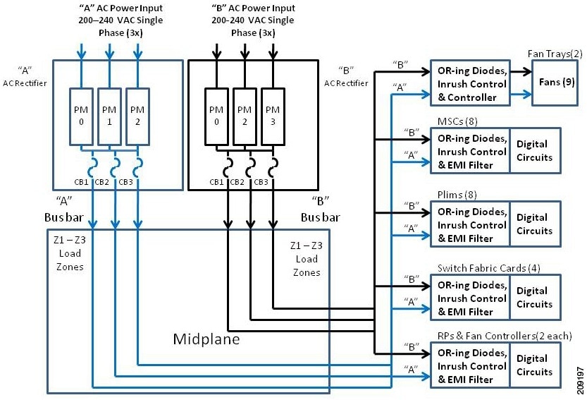
This figure shows the power routing distribution of the 8-slot chassis with a modular AC configuration power system.
Figure 17. CRS 8-Slot Chassis Power Module - Modular AC Configuration
As shown in the figure, AC input power enters the chassis through the A and B power supplies and is distributed to the A
or B power bus. Both buses distribute power through the midplane to the MSC, PLIM, switch fabric, and RP card slots.
Each DC power module provides 2 voltages:
Output voltage 1 is –54 VDC
Output voltage 2 is +5Vaux
Because chassis components are powered by both A and B power inputs, the line card chassis can continue to operate normally
if:
One AC or DC power module fails
One input power (A or B) fails
One internal bus bar fails
One entire power shelf fails
Power modules are added to, or removed from the power shelf
Because no exact redundancy exists across the power modules, individual power modules can be removed without causing the chassis
to lose power.
Individual chassis components have power-related devices, such as OR-ing diodes, inrush control circuits, and EMI filters.
Because any power modules can power all chassis components, these devices can be inserted or removed (OIR) while the chassis
is online. This component insertion and removal is also called hot-swapping
.
The modular configuration AC power shelf has the following input VAC power requirements:
Single-phase, 200 to 240 VAC nominal, 50 to 60 Hz, 16 A
Each power shelf contains three IEC-320-C22 receptacles which can accept up to three IEC-320-C21 connector female plugs, depending
on how many AC PMs are installed in the shelf.
Note
In order to maintain a balanced 3-phase power load, three AC PMs are required to be installed in a Cisco CRS 8-slot line card
chassis AC modular configuration power shelf.
Modular Configuration AC Power Shelf
The AC power shelf is the enclosure that houses the AC power modules and power distribution connections and wiring. The AC
power shelf, shown in this figure, is installed in the Cisco CRS 8-slot line card chassis from the front and plugs into the
chassis power interface connector panel.
Figure 18. Modular Configuration AC Power Shelf
Note
The power cables for the power shelves do not come pre-attached.
Modular Configuration AC Power Module
The AC power module is an AC power module that converts single phase input AC power into the DC power necessary to power chassis
components.
The AC power module (see in this figure) takes input AC power from the power shelf, converts the AC into DC, provides filtering
and control circuitry, provides status signaling, and passes the DC power to the chassis midplane.
Figure 19. Modular Configuration AC Power Module
Each power module has its own power connector to connect input AC power. The input AC power for each power module is as follows:
Each AC power module has a single-phase, 3-wire connection:Input: 200 to 240 VAC, 50 to 60 Hz, 16A. Tolerance: +/-10%(180
to 264) VAC, 50 to 60 Hz, 16A.
A 3-pin IEC-320 C21 90 degree female plug is inserted into a 3-pin IEC-320 C22 male plug at the rear of each power module.
The AC power enters the AC power at the rear of the power shelf. Once the power enters the AC power module, internal circuits
rectify the AC into DC, filter and regulate it. Each AC power module provides two output voltages, as follows:
Output Voltage 1 is -54VDC at 55.5A
Output Voltage 2 is +5V at 0.75A
Each AC power module contains an ID EEPROM that stores information used by control software (for example, part number, serial
number, assembly deviation, special configurations, test history, and field traceability data).
Each AC power shelf supports up to three AC power modules. The AC power modules convert AC power into DC power, provide filtering,
and then distribute the DC power to the chassis midplane. The power shelf also has a service processor module that monitors
the condition of each AC power module and provides status signals that indicate the health of the power supplies.
Modular Configuration AC Power Module Indicators
The following three LED status indicators are located on the front of each AC power module:
Input OK - Green
Output OK - Green
Internal Fault - Red
This table lists the power module status indicators and their functions.
Table 11. AC Power Module Status Indicators
Name
Color
Function
Input OK
Green
Input OK LED turns on continuously when input voltage is present and within the regulation range.
Input OK LED flashes when input voltage is present but not within the regulation range.
Input OK LED is off when input voltage is not present.
Input OK LED flashes when hot-unplugging the power module from the power shelf to indicate that there is energy in the power
module until the input bulk capacitor is completely discharged or the housekeeping circuit is shut down.
Output OK
Green
Output OK LED turns on continuously when power module output voltage is on.
Output OK LED flashes when power module output voltage is in a power limit or an overcurrent situation.
Internal Fault
Red
Internal Fault LED turns on continuously when there is an internal fault in the power module.
The Internal Fault LED on the AC power module is turned on continuously to indicate that one or more of the following internal
faults is detected inside the power module:
5V out of range
Output Stage OT
Fan Fault
OR-ing fault (Output voltage less than bus voltage)
OC shutdown
OT shutdown
OV shutdown
Input stage OT
Fault induced shutdown occurred
Thermal sensor fault
Vout out of range
Boost Vbulk fault
Once all of the faults have been removed and the power module is operating normally, the Internal Fault LED is turned off.
3-Phase AC Power Distribution Unit
This section describes the Cisco CRS Power Distribution Unit (PDU). The PDU converts 3-phase AC input power to single-phase
AC output power that connects directly to the rear of the modular configuration AC power shelf.
Note
The PDU referred to in this document is different from the fixed configuration PDU.
The AC PDU includes either an AC Delta or AC Wye power interface, and has power input and power output cords entering and
exiting the box. The PDU can be installed in a 19-inch rack or other locations, depending on the PDU type, by using chassis
mounting brackets. In this section, single PDU refers to the individual PDU that converts 3-phase AC input power to single-phase
AC output power.
A PDU kit refers to all the components that are required to be installed in a redundant CRS system. A PDU kit contains 2 single
PDUs and any necessary mounting brackets or hardware. When ordering a Cisco CRS system, a PDU kit Product ID should be ordered.
Cisco Product ID numbers for PDU kits are as follows:
CRS-8-PDU-Delta—Redundant 3-phase to single-phase Delta PDU for Cisco CRS 8-slot line card chassis, 2 input/6 output
CRS-8-PDU-Wye—Redundant 3-phase to single-phase Wye PDU for Cisco CRS 8-slot line card chassis, 2 input/6 output
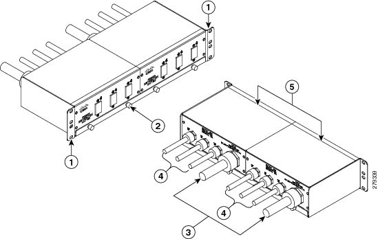
This figure shows the Power Distribution Unit 8D ((Cisco product number PDU-321-3-Delta)) that converts 3-phase AC Delta
input power to single phase output power.
Figure 20. Cisco CRS-8-PDU-Delta
1
Rack mounting ears
2
Rack Tray
3
Input Cord
4
Output Cords
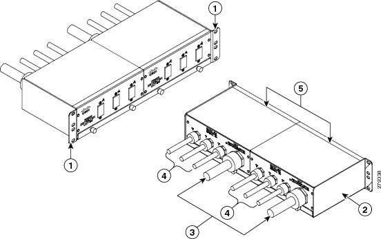
This figure shows the Power Distribution Unit 8W (Cisco product number PDU-321-3-Wye) that converts 3-phase AC Wye input
power to single phase output power.
Figure 21. Cisco CRS-8-PDU-Wye
1
Rack mounting ears
2
Rack Tray
3
Input Cord
4
Output Cords
The PDU for the CRS 8-slot line card chassis is shipped with the following hardware for specific configurations:
Two single AC Delta PDUs with 19 inch rack tray. Each AC Delta PDU has one power input and three outputs.
Two single AC Wye PDUs with 19 inch rack tray. Each AC Wye PDU has one power input and three outputs.


 Feedback