Overview of Line Cards and Physical Layer Interface Modules
The MSC, FP, and LSP card, also called line cards, are the Layer 3 forwarding engine in the CRS 8-slot routing system. Each line card is paired with a corresponding physical layer interface module (PLIM) that contains the packet interfaces for the line card. A line card can be paired with different types of PLIMs to provide a variety of packet interfaces, such as OC-192 POS and OC-48 POS.
- The MSC card is available in the following versions: CRS-MSC (end-of-sale), CRS-MSC-B, CRS-MSC-140G, and CRS-MSC-X/ CRS-MSC-X-L in 200G mode.
- The FP card is available in the following versions: CRS-FP140, CRS-FP-X/CRS-FP-X-L cards in 200G mode).
- The LSP card is: CRS-LSP.
 Note |
For CRS-X next generation line cards and fabric cards, we recommend that you use a modular configuration power system in the chassis. See Modular Configuration Power System, page 2-19 . |
Note |
See CRS Hardware Compatibility, page 1-17 for information about CRS fabric, MSC, and PLIM component compatibility. |
Note |
The following MSC functional description is also generally applicable to the FP and LSP cards, unless noted otherwise. |
Each line card and associated PLIM implement Layer 1 through Layer 3 functionality that consists of physical layer framers and optics, MAC framing and access control, and packet lookup and forwarding capability. The line cards deliver line-rate performance at line rate.
Line cards support several forwarding protocols, including IPV4, IPV6, and MPLS. Note that the route processor (RP) performs routing protocol functions and routing table distributions, while the line card actually forwards the data packets.
Line cards (MSCs, FPs, LSPs) and PLIMs are installed on opposite sides of the line card chassis, and mate through the line card chassis midplane. Each line card and PLIM pair is installed in corresponding chassis slots in the chassis (on opposite sides of the chassis).
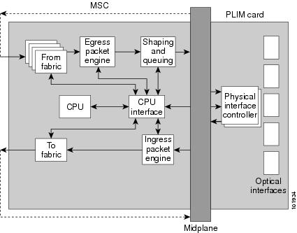
The following figure shows how data enters the optical interfaces on the ingress PLIM and is passed to the ingress MSC. From there, data packets are converted to cells, and forwarded to the switch fabric, where the data cells are switched to the egress MSC and are reassembled into data packets and forwarded out the egress PLIM.

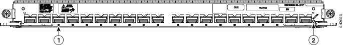
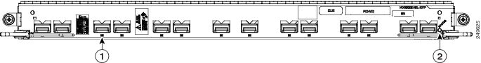
The PLIM provides the interface to user IP data. PLIMs perform Layer 1 and Layer 2 functions, such as framing, clock recovery, serialization and deserialization, channelization, and optical interfacing. Different PLIMs provide a range of optical interfaces, such as very-short-reach (VSR), intermediate-reach (IR), or long-reach (LR).
The line card receives the data from the PLIM and then, based upon the IP packet header, it will perform QoS functionality or other actions, such as the mapping of VLANs. And for ingress data, it will disassemble the packet into 36-byte fabric cells.
This is a simple block diagram of the major components of an MSC/PLIM pair. These components are described in the following sections:
This diagram also applies to the FP and LSP line cards.
PLIM Physical Interface Module On Ingress
Received data enters a PLIM from the physical optical interface. The data is routed to the physical interface controller, which provides the interface between the physical ports, and the Layer 3 function of the MSC. For receive (ingress) data, the physical interface controller performs the following functions:
- Multiplexes the physical ports and transfers them to the ingress packet engine through the line card chassis midplane.
- Buffers incoming data, if necessary, to accommodate back-pressure from the packet engine.
- A GE PLIM provides
Gigabit Ethernet specific functions, such as:
- VLAN accounting and filtering database
- Mapping of VLAN subports
MSC Ingress Packet Engine
The ingress packet engine performs packet processing on the received data. It makes the forwarding decision and places the data into a rate-shaping queue in the “to fabric” section of the board. To perform Layer 3 forwarding, the packet engine performs the following functions:
- Classifies packets by protocol type and parses the appropriate headers on which to do the forwarding lookup
- Determines the appropriate output interface to which to route the data
- Performs access control list filtering
- Maintains per-interface and per-protocol byte-and-packet statistics
- Maintains Netflow accounting
- Implements a flexible dual-bucket policing mechanism
MSC To Fabric Section Queuing
The “to fabric” section of the board takes packets from the ingress packet engine, segments them into fabric cells, and distributes (sprays) the cells into the eight planes of the switch fabric. Because each MSC has multiple connections per plane, the “to fabric” section distributes the cells over the links within a fabric plane. The chassis midplane provides the path between the “to fabric” section and the switch fabric section.
MSC From Fabric Section
The “from fabric” section of the board receives cells from the switch fabric and reassembles the cells into IP packets. The section then places the IP packets in one of its 8K egress queues, which helps the section adjust for the speed variations between the switch fabric and the egress packet engine.
MSC Egress Packet Engine
The transmit (egress) packet engine performs a lookup on the IP address or MPLS label of the egress packet. The egress packet engine performs transmit side features such as output committed access rate (CAR), access lists, diffServ policing, MAC layer encapsulation, and so on.
Shaping and Queuing Function
The transmit packet engine sends the egress packet to the shaping and queuing function (shape and regulate queues function), which contains the output queues. Here the queues are mapped to ports and classes of service (CoS) within a port. Random early-detection algorithms perform active queue management to maintain low average queue occupancies and delays.
PLIM Physical Interface Section On Egress
On the transmit (egress) path, the physical interface controller provides the interface between the MSC and the physical ports on the PLIM. For the egress path, the controller performs the following functions:
- Support for the physical ports.
- Queuing for the ports
- Back-pressure signalling for the queues
- Dynamically shared buffer memory for each queue
- A loopback function where transmitted data can be looped back to the receive side
MSC CPU and CPU Interface
As shown in Figure 2, the MSC contains a central processing unit (CPU) that performs the following functions:
- MSC configuration
- Management
- Protocol control
The CPU subsystem includes:
- A CPU chip
- A Layer 3 cache
- NVRAM
- A flash boot PROM
- A memory controller
- Memory, a dual
in-line memory module (DIMM) socket, providing the following:
- Up to 2 GB of 133 MHz DDR SDRAM on the CRS-MSC
- Up to 2 GB of 166 MHz DDR SDRAM on the CRS-MSC-B
- Up to 8GB of 533 MHz DDR2 SDRAM on the CRS-MSC-140G
- Up to 15GB of 533 MHz DDR3 DIMM on the CRS-MSC-X (200G)
The CPU interface module, provides the interface between the CPU subsystem and the other ASICs on the MSC and PLIM.
The MSC also contains a service processor (SP) module that provides:
- MSC and PLIM power-up sequencing
- Reset sequencing
- JTAG configuration
- Power monitoring
The SP, CPU subsystem, and CPU interface work together to perform housekeeping, communication, and control plane functions for the MSC. The SP controls card power up, environmental monitoring, and Ethernet communication with the line card chassis RP cards. The CPU subsystem performs a number of control plane functions, including receipt of FIB downloads, local PLU and TLU management, statistics gathering and performance monitoring, and MSC ASIC management and fault-handling. The CPU interface drives high-speed communication ports to all ASICs on the MSC and PLIM. The CPU talks to the CPU interface through a high-speed bus attached to its memory controller.


 Feedback