VXLAN Static Routing

VXLAN static routing provides a method for connecting multiple servers in a data center to an enterprise edge router.

This chapter provides information on VXLAN static routing configuration.

VXLAN Static Routing

Table 1. Feature History Table

Feature Name

Release Information

Feature Description

VXLAN Static Routing

Release 7.11.1

Introduced in this release on:NCS 5500 fixed port routers;NCS 5700 fixed port routers;NCS 5500 modular routers(NCS 5700 line cards [Mode: Native])

You can now configure the source and destination virtual tunnel endpoints (VTEPs) for a particular traffic flow, which is particularly useful for scenarios where your data center is connected to an enterprise network, so multiple servers in the data center provide cloud services to your customers and the enterprise edge router. These endpoints help provide rapid convergence in case of failure. Plus, using the UDP header in the VXLAN packet, the VXLAN static routing (also called unicast VXLAN) facilitates network balancing by preventing the transmission of replicated packets.

The feature introduces these changes:

CLI:

YANG Data Model:

Introduction to VXLAN

Traditionally, Virtual Local Area Networks (VLANs) are used to partition a single physical network into multiple logical networks. With VLANs, every VLAN has a VLAN ID, which is added to a frame to keep traffic unique. The VLAN ID is 12-bits long, allowing around 4000 unique VLANs.

But in today's networks, you might have a data center with lots of virtualization and need to isolate several virtual machines (VMs) from other VMs where you could easily run out of VLANs. So, there is a need to provide robust tunneling mechanisms to isolate and load-balance traffic inside the provider’s network.

Virtual Extensible LAN (VXLAN) addresses some of the limitations of traditional VLANs in large-scale and cloud-based environments. VXLAN is widely used in data center environments where there is a need for virtualized networks to support cloud computing and virtualization technologies. It is also used in service provider networks to provide virtualized network services to customers.

VXLAN is a Layer 2 tunneling protocol that connects multiple servers in a data center that provide cloud services to customers and the enterprise edge router and stretches Layer 2 networks over an underlying Layer 3 IP network. VXLAN automatically configures underlay tunnels between the router and servers and overlay routing within those tunnels. VXLAN creates virtual networks on top of an underlay network. The underlay network is typically a physical IP network. VXLAN underlay can be IPv4 packets. The underlay and overlay networks are independent, and changes in the underlay don't affect the overlay. You can add or remove a router in the underlay network without affecting the overlay network.

VXLAN allows you to tunnel Ethernet frames over IP transport that uses IP and UDP as the transport protocol. A tunnel is created that enables you to extend a Layer 2 segment over a Layer 3 network using MAC-in-UDP encapsulation. A VXLAN header is added to the Layer 2 frame and placed inside a UDP packet to send to the routed domain. The VXLAN tunnel endpoint (VTEP) is a router that encapsulates and de-encapsulates Layer 2 traffic. VTEP encapsulates Layer 2 Ethernet frames within the Layer 4 User Datagram Protocol (UDP) and transports the encapsulated frames over a Layer 3 network. For more information on VTEP, see VXLAN Tunnel Endpoint.

VXLAN introduces an 8-byte VXLAN header that consists of a 24-bit VXLAN network identifier (VNI) with the original Ethernet frame added in the UDP payload. The 24-bit VNI is used to identify Layer 2 segments and maintain Layer 2 isolation between the segments.

With all 24 bits in VNI, VXLAN can support 16 million LAN segments. The VNI is used to designate the individual VXLAN overlay network on which the communicating virtual machines (VMs) are situated. VMs in different VXLAN overlay networks cannot communicate with each other.

When a host sends traffic:

  • The VXLAN encapsulates the traffic in UDP and IP headers.

  • VXLAN encodes the flow information in the UDP source port to enable routers to perform flow-based load balancing.

    Flow-based load balancing identifies different flows of traffic based on the key fields in the data packet. For example, IPv4 source and destination IP addresses can be used to identify a flow.

  • VXLAN encapsulates these packets into the tunnel with an IPv4 outer header.

  • After the traffic reaches the destination router, the router decapsulates the packet and sends it to the destination host.

  • VXLAN adds the custom source MAC address in the inner header that encodes the information in the MAC address where your internal network devices can extract the required information.

Benefits of VXLAN

  • High throughput through dedicated VPN connectivity between servers and enterprise edge routers.

  • Allows the creation of overlay networks independent of the underlying physical network, which provides greater flexibility in network design and deployment.

  • Flexible placement of multitenant segments throughout the data center with the creation of isolated virtual networks for multiple tenants, providing greater security and separation between different users. Multitenants are multiple independent tenants or customers on a shared infrastructure.

  • Provides a solution to extend Layer 2 segments over the underlying shared network infrastructure so that workload of a tenant can be placed across physical pods in the data center. Physical pod is a group of computing, networking, and storage resources that can be configured and allocated to a particular tenant.

  • Facilitates network load balancing using the source UDP port within the VXLAN outer header.

Compared to VLAN, VXLAN uses higher scalability to address more Layer 2 segments and utilizes available network paths in the underlying infrastructure in a better way.

The following table describes how VLAN and VXLAN use the scalability and available network paths:

VLAN

VXLAN

VLANs use a 12-bit VLAN ID to address Layer 2 segments, which results in limiting scalability of only 4094 VLANs.

VXLAN uses a 24-bit segment ID known as the VXLAN network identifier (VNID), which enables up to 16 million VXLAN segments to co-exist in the same administrative domain.

VLAN uses the Spanning Tree Protocol for loop prevention, which ends up not using half of the network links in a network by blocking redundant paths.

VXLAN packets are transferred through the underlying network based on its Layer 3 header and can take complete advantage of Layer 3 routing, equal-cost multipath (ECMP) routing, and link aggregation protocols to use all available paths.

VXLAN Static Routing

You can use VXLAN static routing to interconnect non-VXLAN, such as MPLS and VXLAN domains. VXLAN static routing defines the path for VXLAN traffic from the source VTEP to reach the destination VTEP and involves configuring static routes on the underlying Layer 3 network to direct the VXLAN traffic to the appropriate VTEPs.

Benefits of Static VXLAN

  • You can use static routes in scenarios where consistent routing decisions are required. Because the static routes are manually configured and the routing behavior is predictable and stable.

  • You can specify the next hop for each destination using static routes and thereby have direct control over traffic.

  • Static routes are useful for specific traffic engineering or policy requirements.

  • You do not have to maintain routing tables for static routing, hence reduces any overhead associated with routing protocols.

VXLAN Packet Format

VXLAN defines a MAC-in-UDP encapsulation scheme where the original Layer 2 frame has a VXLAN header added and is then placed in a UDP-IP packet. With this MAC-in-UDP encapsulation, VXLAN tunnels Layer 2 network over Layer 3 network. The following illustration shows VXLAN packet format:

Figure 1. VXLAN Packet Format

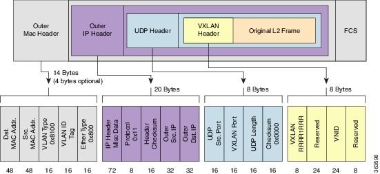
VXLAN introduces an 8-byte VXLAN header that consists of a 24-bit VNID and a few reserved bits. The VXLAN header together with the original Ethernet frame goes in the UDP payload. The 24-bit VNID is used to identify Layer 2 segments and to maintain Layer 2 isolation between the segments. With all 24 bits in VNID, VXLAN can support approximately 16 million LAN segments.

The following table describes the VXLAN fields with parameters:

Field

Parameters

Outer Mac Header

  • Destination MAC Address

  • Source MAC Address

  • VLAN Type

  • VLAN ID

  • Ethernet Type

Outer IP Header

  • IP Header

  • Protocol

  • IP header checksum

  • Outer source IP address

  • Outer destination IP address

UDP Header

  • UDP source port

  • VXLAN port

  • UDP length

  • UDP checksum

VXLAN Header

  • VXLAN Flags - 8 bits

  • VNI - 24 bits. VNI is VXLAN Network Identifier used to identify a VXLAN segment

  • Reserved fields - 24 bits and 8 bits

VXLAN Tunnel Endpoint

A VXLAN tunnel endpoint (VTEP) can be a physical or virtual router that connects the overlay and the underlay networks. A VTEP device is identified in the IP transport network using a unique IP address, which is a loopback interface IP address. The VTEP device uses this IP address to encapsulate Ethernet frames and transmits the encapsulated packets to the transport network through the IP interface. A source and destination VTEP creates a stateless tunnel to deliver traffic from one host to another. When a frame for a remote host reaches a device, the frame is encapsulated in IP and UDP headers. A maximum of 8k VXLAN tunnel interface per VTEP is supported.

Load Sharing with VXLANs

Most data center transport networks are designed and deployed with multiple redundant paths that utilize various multipath load-sharing technologies to distribute traffic loads on all available paths. Encapsulated VXLAN packets are forwarded between VTEPs based on the native forwarding decisions of the transport network.

A typical VXLAN transport network is an IP-routing network that uses the standard IP equal cost multipath (ECMP) to balance the traffic load among multiple best paths. To avoid out-of-sequence packet forwarding, flow-based ECMP is commonly deployed. An ECMP flow is defined by the source and destination IP addresses.

All the VXLAN packet flows between a pair of VTEPs have the same outer source and destination IP addresses. All VTEP devices must use one identical destination UDP port, either the Internet Allocated Numbers Authority (IANA)-allocated UDP port 4789 or a customer-configured port. The source UDP port is the only variable element in the ECMP flow definition that can differentiate VXLAN flows from the transport network standpoint. The VXLAN outer-packet header uses source UDP port for link load-share hashing, which is the only element that can uniquely identify a VXLAN flow. A VXLAN flow is unique as the VXLAN inner frame header considers the VXLAN source UDP port for load balancing.

Encapsulation

The encapsulation of VXLAN packets happens based on the outgoing packets:

  • The destination IP and the egress VNI are derived from the L2VPN configuration.

  • The source IP is the local Network Virtualization Endpoint (NVE) interface.

  • The destination UDP port is the configured NVE destination UDP port.

  • The source UDP port is allocated by the router.

Decapsulation

The decapsulation of VXLAN packets happens based on the incoming packets:

  • The destination IP and destination UDP port are used to attract traffic in underlay network.

  • The destination IP is the NVE source IP.

  • Local router listens to destination UDP port based on locally configured NVE destination UDP port.

  • The service is identified by destination IP, source IP, and VNI at disposition.

  • The service is held by the PWHE interface.

  • The source IP identifies the remote VRF source IP.

  • The source UDP port is allocated by the remote router.

Implement ACL and QoS for VXLAN

You can configure Access Control List (ACL) and QoS for VXLAN. The VXLAN decapsulation for ingress ACL and ingress QoS happens over PW-Ether interfaces. If Layer 3 ACL is configured on PW-Ether interface, the flow remains the same as on a regular interface.


Note


The VXLAN encapsulation is not supported on ACL and QoS configurations, as egress ACL and egress QoS are not supported.


Restrictions for VXLAN Static Routing

  • Only IPv4 VXLAN tunnels are supported.

  • An underlay network cannot be protected by ECMP or Fast Reroute (FRR).

  • Egress Traffic Management (ETM) support is required and all the Generic Interface List (GIL) members must be ETM-enabled. A GIL contains list of physical or bundle interfaces used in a PWHE connection.

  • Non-ETM interfaces are not supported in GIL. If GIL is not enabled with ETM, the traffic will drop and will not be forwarded to the destination tunnel.

  • Mixed mode ETM, which is a combination of ETM and non-ETM members in a GIL, is not supported.

  • FRR and multipath are not supported with ETM. For ETM to work, it is mandatory that the transport paths are unprotected (non-FRR) and unipath.


Note


For more information on ETM, see the Configure Egress Traffic Management section in the Modular QoS Configuration Guide for Cisco NCS 5500 Series Routers.


Configure Static VXLAN

Perform the following tasks to configure a VXLAN tunnel.

  1. Configure the Generic Interface List (GIL). A GIL contains list of physical or bundle interfaces used in a PWHE connection.

  2. Configure ETM mode for the GIL members.

  3. Configure VRF. The VRF is used to divide the VXLAN tenants.

  4. Configure Pseudowire Headend (PWHE). Assign the VRF and attach the GIL to the PWHE interface.

  5. Optionally, you can configure egress QoS on PWHE Interface, to implement QoS.

  6. Configure Network Virtualization Endpoint (NVE) interface and assign a VXLAN Network Identifier (VNI) to the NVE. The NVE is a local tunnel endpoint (LTEP) manager which publishes Uplink-LTEP. The VNI ID is used to identify the endpoint along with source IP and destination IP addresses.

  7. Configure L2VPN cross-connect and assign the PWHE interface. Configure static routing and VXLAN encapsulation. Configure the neighbor with destination IP for VXLAN.

Prerequisites

  • Ensure that the native mode is enabled on the router. You can use the hw-module profile npu native-mode-enable command to enable the native mode.

  • Ensure that hardware MDB profiles are configured using the hw-module profile mdb l3max-se command.

  • Ensure that all the GIL members are ETM-enabled.

Configuration Examples

Configure the GIL:


Router(config)# generic-interface-list txlist
Router(config-gen-if-list)# interface HundredGigE0/0/0/33

Configure ETM mode for the GIL members:


Router(config)# controller Optics0/0/0/33
Router(config-Optics)# mode etm

Configure VRF:


Router(config)# vrf vrf193
Router(config-vrf)# address-family ipv4 unicast

Configure PWHE, assign the VRF, and attach the GIL to the PWHE interface:


Router(config)# interface PW-Ether1
Router(config-if)# mtu 1518
Router(config-if)# vrf vrf193
Router(config-if)# ipv4 address 10.0.0.1 255.255.255.0
Router(config-if)# attach generic-interface-list txlist

Configure Egress QoS on PWHE nterface:


/* Create a QoS Policy */
Router(config)# policy-map test_etm
Router(config-pmap)# class class-default
Router(config-pmap-c)# shape average percent 2
Router(config-pmap-c)# exit
Router(config-pmap)# end-policy-map

/* Apply the policy on PWHE interface */
Router(config)# interface PW-Ether1
Router(config-if)# service-policy output test_etm
Router(config-if)# mtu 1518
Router(config-if)# vrf vrf193
Router(config-if)# ipv4 address 10.0.0.1 255.255.255.0
Router(config-if)# attach generic-interface-list txlist
Router(config-if)# commit

Configure Ingress QoS on PWHE interface:


/* Create a QoS Policy */
Router(config)# class-map match-any dscp10
Router(config-cmap)# match dscp 10 
Router(config-cmap)# end-class-map
Router(config)# policy-map ing
Router(config-pmap)# class dscp10
Router(config-pmap-c)# set traffic-class 1
Router(config-pmap-c)# exit
Router(config-pmap)# class class-default
Router(config-pmap-c)# exit          
Router(config-pmap)# end-policy-map 

/* Apply the policy on PWHE interface */
Router(config)# interface pw-ether 1
Router(config-if)# service-policy input ing
Router(config-if)# commit

Configure NVE interface:


Router(config)# interface nve1
Router(config-if)# member vni 5000
Router(config-nve-vni)# host-reachability protocol static
Router(config-nve-vni)# overlay-encapsulation vxlan
Router(config-if)# source-interface Loopback123
Router(config-if)# exit
Router(config)# interface Loopback123
Router(config-if)# ipv4 address 123.1.1.10 255.255.255.255

Configure L2VPN cross-connect:


Router(config)# l2vpn
Router(config-l2vpn)# xconnect group xg1
Router(config-l2vpn-xc)# p2p xp1
Router(config-l2vpn-xc-p2p)# interface PW-Ether1
Router(config-l2vpn-xc-p2p)# neighbor ipv4 123.1.1.13 nve1 vni 5000

Verification

The following outputs show GIL configuration and the status of GIL.


Router# show gil ma idb
 
GIL MA IDB Database:                                                                                                                                            
====================                                                                                                                                            
GIL name: txlist, ifhandle: 0xb0                                                                                                                                  
  State: Up                                                                                                                                                     
  Flags: 0x2                                                                                                                                                    
  Members:                                                                                                                                                      
    GigabitEthernet0/2/0/2                                                                                                                                      
      Flags: 0x2                                                                                                                                                
    GigabitEthernet0/2/0/0
      Flags: 0x2
  Retry timer:
    Delay: 0 ms, Running: n, Remaining: 0 ms
    Statistics:
      Expiry count   : 0
      Start count    : 0
      Stop count     : 0
Router# show gil ea idb location 0/2/CPU0

GIL EA IDB Database:
====================
GIL name: txlist, ifhandle: 0xb0
  State: Up
  Flags: 0x0
  NPU mask: 0x0

The following output shows that PWHE interface state is up with GIL attached to PWHE.

Router# show interfaces PW-Ether1
PW-Ether1 is up, line protocol is up
  Interface state transitions: 11
  Hardware is PWHE Ethernet Interface, address is e8c5.7a08.6088
  Internet address is 10.0.0.1/24
  MTU 1518 bytes, BW 10000 Kbit (Max: 10000 Kbit)
     reliability 255/255, txload 0/255, rxload 0/255
  Encapsulation ARPA,  loopback not set,
  Last link flapped 00:22:10
  ARP type ARPA, ARP timeout 04:00:00
    L2Overhead: 0
    Generic-Interface-List: txlist
  Last input Unknown, output Unknown
  Last clearing of "show interface" counters Unknown
  5 minute input rate 0 bits/sec, 0 packets/sec
  5 minute output rate 0 bits/sec, 0 packets/sec
Router# show l2vpn pwhe interface pw-ether 1 detail

Interface: PW-Ether1   Interface State: Up, Admin state: Up
  Interface handle 0x190
  MTU:  1518
  BW:   10000 Kbit
  Interface MAC addresses: 02ef.af8d.8008
  Label: 0
  Internal ID: ::ffff:10.0.0.2
  L2-overhead: 0
  VC-type: 5
  CW: N
  Generic-interface-list: txlist (id: 0)
Router# show l2vpn ea pwhe ifhandle 0x190 location 0/2/CPU0

 
----- node0_2_CPU0 -----
  ifName       ifHandle    ifType ifState L2OvrHd  MTU    BW
-----------------------------------------------------------------
PW-Ether1     0x00000190 0x00000052  Up      0    1514    10000

The following output shows the egress QoS policy configuration.

Router# show policy-map interface pw-ether 1

PW-Ether1 direction input: Service Policy not installed
PW-Ether1 output: test_etm

Class class-default
Classification statistics (packets/bytes) (rate - kbps)
Matched : 3381299546/628921715370 12567575
Transmitted : 544297875/101239404750 2023090
Total Dropped : 2837001671/527682310620 10544485
Queueing statistics
Queue ID : None (Pseudo-Wire)
Taildropped(packets/bytes) : 2837001671/527682310620

The following outputs shows the ingress QoS policy configuration.

Router# show qos interface pw-ether 1 input 

PW-Ether1 direction input: dir ifhadle 2000802c
NOTE:- Configured values are displayed within parentheses
Interface PW-Ether1 Ifh 0x2000802c (PWHEMain)
NPU Id:                        0
Total number of classes:       2
Interface Bandwidth:           100000000 kbps
Policy Name:                   ing
SPI Id:                        0x0
Accounting Type:               Layer2 (Include Layer 2 encapsulation and above)
------------------------------------------------------------------------------
Level1 Class                             =   dscp10
New traffic class                        =   1

Default Policer Bucket ID                =   0x621
Default Policer Stats Handle             =   0x0
Policer not configured for this class

Level1 Class                             =   class-default

Default Policer Bucket ID                =   0x620
Default Policer Stats Handle             =   0x0
Policer not configured for this class

HundredGigE0/0/0/26 direction input: dir ifhadle 2000802c
Interface HundredGigE0/0/0/26 Ifh 0x248 (Member) -- input policy
NPU Id:                        0
Total number of classes:       2
Interface Bandwidth:           100000000 kbps
Policy Name:                   ing
SPI Id:                        0x0
Accounting Type:               Layer2 (Include Layer 2 encapsulation and above)
------------------------------------------------------------------------------
Level1 Class                             =   dscp10

Level1 Class                             =   class-default
Router# show policy-map interface pw-ether1 input
Class dscp10
  Classification statistics          (packets/bytes)     (rate - kbps)
    Matched             :           227525526/29123267328          0
    Transmitted         :           227525526/29123267328          0
    Total Dropped       :                   0/0                    0
Class class-default
  Classification statistics          (packets/bytes)     (rate - kbps)
    Matched             :                6631/848768               0
    Transmitted         :                6631/848768               0
    Total Dropped       :                   0/0                    0

The following output verifies that PW-Ether interface is replicated.

Router# show im database interface pw-ether 1 verbose
Fri Jan 27 19:11:59.141 EST                                                                                                                                     
                                                                                                                                                                  
View: OWN - Owner, L3P - Local 3rd Party, G3P - Global 3rd Party, LDP - Local Data Plane                                                                        
      GDP - Global Data Plane, RED - Redundancy, UL - UL                                                                                                        
                                                                                                                                                                  
Node 0/0/CPU0 (0x0)                                                                                                                                             
                                                                                                                                                                  
Interface PW-Ether1, ifh 0x00000190 (up, 1514)                                                                                                                  
  Interface flags:          0x00000000000285d7 (REPLICATED|DYN_REP|IFINDEX                                                                                      
                            |SUP_NAMED_SUB|BROADCAST|VIRTUAL|CONFIG|VIS|DATA                                                                                    
                            |CONTROL)
 
....     
 
  UL interface - UL|GDP|G3P|L3P|OWN     |Repl data len, b                      |
  --------------------------------------|--------------------------------------|
  gil-gil1                  (0x000000b0)                                      0
 
  Node 0/2/CPU0
  ----------------
    PICs
    ----
    0x00000000 00000001
 
    Underlying interface                  | Base interfaces
    --------------------------------------|--------------------------------------
    gil-gil1                  (0x000000b0) GigabitEthernet0/2/0/2    (0x01000080)
                                           GigabitEthernet0/2/0/0    (0x01000040)
 

The following output shows that NVE interface is up with the encapsulation type as VXLAN.

Router# show nve interface nve1
Interface: nve1 State: Up Encapsulation: VxLAN
  Source Interface: Loopback123 (primary: 123.1.1.10)

Verify the L2VPN cross-connect configuration, which provisions a VXLAN tunnel:

Router# show l2vpn xconnect
 
Legend: ST = State, UP = Up, DN = Down, AD = Admin Down, UR = Unresolved,
        SB = Standby, SR = Standby Ready, (PP) = Partially Programmed,
        LU = Local Up, RU = Remote Up, CO = Connected, (SI) = Seamless Inactive
 
XConnect                   Segment 1                       Segment 2               
Group      Name       ST   Description            ST       Description            ST   
------------------------   -----------------------------   -----------------------------
xg1        xp1        UP   PE1                    UP       VXLAN 123.1.1.13,1,5000
                                                                                  UP
----------------------------------------------------------------------------------------