Appendix

Certain troubleshooting aids of the Cisco N540-24Q8L2DD-SYS enable you to perform these tasks that assist the troubleshooting process:

LEDs

The details of LEDs are listed in this section.

Router LEDs

All the data port LEDs in the Cisco NCS 540 Router is at the front panel. There are 5 LEDs that reflect the different statuses of the system.

Table 1. Router LED Descriptions

LED

Color

Status

Alarm

Red

Critical alarm - system-scope (including RP0).

Amber

Major alarm - system-scope (including RP0).

Flashing Amber

Minor alarm - system-scope (including RP0).

Off

No alarm.

Status

Green

The module is operational but has no active major or critical alarms.

Amber

Host kernel booted and XR is booting.

Flashing Red

Not Applicable.

SYNC

Green

Time core is synchronized to an external source including IEEE1588.

Flashing Green

System is in Synchronous Ethernet mode.

Amber

Acquiring state or Holdover: Time core is in acquiring state or holdover mode.

Off

Time core clock synchronization is disabled or in free-running state.

GNSS

Off

GNSS is not configured.

Green

GNSS Normal State. Self-survey is complete.

Red

Power up. GNSS is not tracking any satellite.

Amber

Auto holdover.

Flashing Green

Learning state–normal. Self-survey is not completed.

System Fans LED

Cisco N540-24Q8L2DD-SYS has six fans at the back panel.

Table 2. Fan Assembly LED Descriptions
LED Color Status

STATUS

Green

Fans are operating normally.

Amber

Single fan failure.

Red

More than one fan failure or a single PSU fan failure.

Off

Fan tray is not receiving power.

Power Status LEDs

Table 3. Power Status LEDs

LED Label

Color

Status

PWR

Off

Sytem is powered off

Green

All the power supplies are on and operating normally.

Amber

Standby FPGA upgrade is in progress (this is expected to take about three to five minutes).

Red

Power redundancy is lost due to a power feed failure or an internal power supply failure.

Power Supply LEDs (PM0/PM1)

Table 4. Power Supply LED (PM0/PM1) Descriptions

POWER LED

FAIL LED

Power Supply Condition

Green

Off

Power Supply ON; valid input/output.

Amber 1Hz flashing

Red 1Hz flashing

PSU Warning due to:

  • Over current

  • Over temperature

  • Under voltage

  • Over voltage

  • Over power

  • Fan failure

Off

On

PSU failure due to:

  • Over current

  • Over temperature

  • Under voltage

  • Over voltage

  • Over power

  • Fan failure

Green 1Hz flashing

Off

Power supply is not plugged in to the chassis or shutdown by the system.

Off

Off

No valid power input.

Amber

Off

Low input voltage.

Front Panel Power LED and Fan LED Combination

Table 5. Front Panel Power LED and Fan LED Combination

Fan LED

Power LED

Status

Off

Red

Power failure with one of the input power feeds failed or one of the on-board voltage rails has failed.

Amber

STDBY FPGA upgrade is in progress due to post Reload/Power cycle after HW FPD upgrade All.

Note

 
Upgrade of the STDBY FPGA takes 3–5 minutes.

Green

Flashing Amber

Thermal shutdown with no fan

Flashing Red

Flashing Red

Thermal shutdown

Flashing Red

Flashing Amber

MSS Ready=0

Flashing Amber

Flashing Green

TAM init fail

Flashing Amber

Flashing Red

TAM Not Ready

Flashing Amber

Flashing Amber

SECURE JTAG Fail

Flashing Green

Flashing Green

BIOS Validation Failure

Off

Green

Power Supply ON and operating normally.

System Specifications

For information on the system specifications, see the Cisco Network Convergence System Large Density 540 Routers Data Sheet.

Weight and Power Consumption

For information on physical specifications and power consumption, see the Cisco Network Convergence System Large Density 540 Routers Data Sheet.

Environmental Specifictaions

For information on environmental specifications, see table Environmental properties for NCS 540 fixed systems on the Cisco Network Convergence System 540 Large Density Routers Data Sheet.

RJ-45 Connectors

The RJ-45 connector connects Category 3, Category 5, Category 5e, Category 6, or Category 6A foil twisted-pair or unshielded twisted-pair cable from the external network to the following module interface connectors:

  • Router chassis

    • CONSOLE port

    • MGMT ETH port

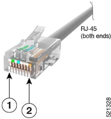
The following figure shows the RJ-45 connector.

Figure 1. RJ-45 Connector

Console Port Pinouts

This following table summarizes the Console port pinouts:

Table 6. Console Port Pinouts

Pin

Signal Name

Direction

Description

1

ACONS-TX

Output

Aux Consoles transmit output, RS232

2

NC

NA

NA

3

CONS-TX

Output

Console RS232 transmit

4

Gnd

NA

Ground

5

Gnd

NA

Ground

6

CONS-RX

Input

Console RS232 receive

7

ACONS-RTX

Input

Aux Consoles receive input, RS232

8

NC

NA

NA

Management Ethernet Port Pinouts

This following table summarizes the Management Ethernet port pinouts:

Table 7. Management and PTP Ethernet Port Pinouts

Pin

Signal Name

1

TRP0+

2

TRP0-

3

TRP1+

4

TRP1-

5

TRP2+

6

TRP2-

7

TRP3+

8

TRP3-

Timing Port Pinouts

The platform is capable of receiving or sourcing timing signals of 1 PPS & 10 MHz. These interfaces are provided by two mini-coax 50-Ohm, 1.0/2.3 DIN series connector on the front panel. Similarly there are two mini-coax 50-Ohm connectors provided in the front panel to output this 1PPS and 10MHz.

This table below summarizes the timing port pinouts:

Table 8. Timing Port Pinouts

10 MHz (Input and Output)

1PPS (Input and Output)

Waveform

Input—Sine wave

Output—Square wave

Input—Rectangular pulse

Output—Rectangular pulse

Amplitude

Input— > 1.7 volt p-p(+8 to +10 dBm)

Output— > 2.4 volts TTL compatible

Input— > 2.4 volts TTL compatible

Output— > 2.4 volts TTL compatible

Impedance

50 ohms

50 ohms

Pulse Width

50% duty cycle

26 microseconds

Rise Time

Input—AC coupled

Output—5 nanoseconds

40 nanoseconds

Time-of-Day Port Pinouts

This table summarizes the ToD/1-PPS port pinouts:

Table 9. RJ-45 ToD/1-PPS Port Pinouts

Pin

Signal Name

Direction

Description

1

2

3

1PPS_N

Output or Input

1PPS RS422 signal

4

GND

5

GND

6

1PPS_P

Output or Input

1PPS RS422 signal

7

TOD_N

Output or Input

Time-of-Day character

8

TOD_P

Output or Input

Time-of-Day character

USB Port Pinouts

This following table summarizes the USB port pinouts:

Table 10. USB Port Pinouts

Pin

Signal Name

Description

A1

Vcc

+5 VDC

A2

D-

Data -

A3

D+

Data +

A4

Gnd

Ground

Alarm Port Pinouts

This following table summarizes the external alarm input pinouts:

Table 11. External Alarm Input Pinouts

Pin

Signal Name

Description

1

ALARM0_IN

Alarm input 0

2

ALARM1_IN

Alarm input 1

3

4

ALARM2_IN

Alarm input 2

5

ALARM3_IN

Alarm input 3

6

7

8

ALARM_IN_COMMON

Alarm Input Common

AC Power Cord Specifications

For more information on the supported power cables, see Ordering information for power cables supported on NCS 540 on the Cisco Network Convergence System 540 Large Density Routers Data Sheet.