Configuring Ethernet Interfaces

This module describes the configuration of Ethernet interfaces.

The following distributed ethernet architecture delivers network scalability and performance, while enabling service providers to offer high-density, high-bandwidth networking solutions.

  • 1-Gigabit

  • 10-Gigabit

  • 25-Gigabit

  • 40-Gigabit

  • 100-Gigabit


Tip


You can programmatically configure and manage the Ethernet interfaces using openconfig-ethernet-if.yang and openconfig-interfaces.yang OpenConfig data models. To get started with using data models, see the Programmability Configuration Guide for Cisco NCS 540 Series Routers.


These solutions are designed to interconnect the router with other systems in point-of-presence (POP)s, including core and edge routers and Layer 2 and Layer 3 switches.

Restrictions for Configuring Ethernet Interfaces

  • Router does not support configuration of the static mac address.

  • As per design, traffic logs for incoming CRC error packets don’t display packets per second (PPS) and other packet-specific information, as highlighted below.

    Router# show interface tenGigE 0/0/0/10 | include packets 
      
    5 minute input rate 541242000 bits/sec, 0 packets/sec 
    5 minute output rate 0 bits/sec, 0 packets/sec 
       0 packets input, 7718374402816 bytes, 0 total input drops 
       Received 0 broadcast packets, 0 multicast packets 
       2952 packets output, 389664 bytes, 0 total output drops 
       Output 0 broadcast packets, 2952 multicast packets 
     
    
  • The router doesn’t support connecting a 1Gig copper cable to a 25GbE or higher speed QSFP ports.

  • For 1Gig fibre cable, the router doesn’t support auto-negotiation for 25GbE or higher speed QSFP ports.

Configuring Physical Ethernet Interfaces

Use this procedure to create a basic Ethernet interface configuration.

Procedure


Step 1

show version

Example:


RP/0/RP0/CPU0:router# show version

(Optional) Displays the current software version, and can also be used to confirm that the router recognizes the line card.

Step 2

show interfaces [GigE | TenGigE | TwentyFiveGigE| FortyGigE | HundredGigE] interface-path-id

Example:


RP/0/RP0/CPU0:router# show interface HundredGigE 0/0/1/0

(Optional) Displays the configured interface and checks the status of each interface port.

Step 3

configure

Example:


RP/0/RP0/CPU0:router# configure terminal

Enters global configuration mode.

Step 4

interface [GigE | TenGigE| TwentyFiveGigE| FortyGigE | HundredGigE] interface-path-id

Example:


RP/0/RP0/CPU0:router(config)# interface HundredGigE 0/0/1/0

Enters interface configuration mode and specifies the Ethernet interface name and notation rack/slot/module/port. Possible interface types for this procedure are:

  • GigE

  • 10GigE

  • 25GigE

  • 40GigE

  • 100GigE

    Note

     
    • The example indicates a 100-Gigabit Ethernet interface in the line card in slot 1.

The supported interface-path-id ranges are:

  • GigE — 0/0/0/0 - 0/0/0/31

  • TenGigE — 0/0/0/0 - 0/0/0/31

  • TwentyFiveGigE — 0/0/0/24 - 0/0/0/31

  • FortyGigE — 0/0/1/0 - 0/0/1/1

  • HundredGigE — 0/0/1/0 - 0/0/1/1

Step 5

ipv4 address ip-address mask

Example:


RP/0/RP0/CPU0:router(config-if)# ipv4 address 172.18.189.38 255.255.255.224

Assigns an IP address and subnet mask to the interface.

  • Replace ip-address with the primary IPv4 address for the interface.

  • Replace mask with the mask for the associated IP subnet. The network mask can be specified in either of two ways:

  • The network mask can be a four-part dotted decimal address. For example, 255.0.0.0 indicates that each bit equal to 1 means that the corresponding address bit belongs to the network address.

  • The network mask can be indicated as a slash (/) and number. For example, /8 indicates that the first 8 bits of the mask are ones, and the corresponding bits of the address are network address.

Step 6

mtu bytes

Example:


RP/0/RP0/CPU0:router(config-if)# mtu 2000

(Optional) Sets the MTU value for the interface.

  • The configurable range for MTU values is 1514 bytes to 9646 bytes.

  • The default is 1514 bytes for normal frames and 1518 bytes for 802.1Q tagged frames.

Step 7

no shutdown

Example:


RP/0/RP0/CPU0:router(config-if)# no shutdown

Removes the shutdown configuration, which forces an interface administratively down.

Step 8

show interfaces [GigE TenGigE TwentyFiveGigE TwentyFiveGigE FortyGigE HundredGigE ] interface-path-id

Example:


RP/0/RP0/CPU0:router# show interfaces HundredGigE 
0/0/1/0

(Optional) Displays statistics for interfaces on the router.


Example

This example shows how to configure an interface for a 100-Gigabit Ethernet line card:


RP/0/RP0/CPU0:router# configure 
RP/0/RP0/CPU0:router(config)# interface HundredGigE 0/0/1/0 
RP/0/RP0/CPU0:router(config-if)# ipv4 address 172.18.189.38 255.255.255.224 

RP/0/RP0/CPU0:router(config-if)# mtu 2000 

RP/0/RP0/CPU0:router(config-if)# no shutdown 
RP/0/RP0/CPU0:router(config-if)# end 
Uncommitted changes found, commit them? [yes]: yes 

RP/0/RP0/CPU0:router# show interfaces HundredGigE 0/0/1/0 
HundredGigE0/0/1/0 is up, line protocol is up
  Interface state transitions: 1
  Hardware is HundredGigE, address is 6219.8864.e330 (bia 6219.8864.e330)
  Internet address is 3.24.1.1/24
  MTU 9216 bytes, BW 100000000 Kbit (Max: 100000000 Kbit)
     reliability 255/255, txload 3/255, rxload 3/255
  Encapsulation ARPA,
  Full-duplex, 100000Mb/s, link type is force-up
  output flow control is off, input flow control is off
  Carrier delay (up) is 10 msec
  loopback not set,
  Last link flapped 10:05:07
  ARP type ARPA, ARP timeout 04:00:00
  Last input 00:08:56, output 00:00:00
  Last clearing of "show interface" counters never
  5 minute input rate 1258567000 bits/sec, 1484160 packets/sec
  5 minute output rate 1258584000 bits/sec, 1484160 packets/sec
     228290765840 packets input, 27293508436038 bytes, 0 total input drops
     0 drops for unrecognized upper-level protocol
     Received 15 broadcast packets, 45 multicast packets
              0 runts, 0 giants, 0 throttles, 0 parity
     0 input errors, 0 CRC, 0 frame, 0 overrun, 0 ignored, 0 abort
     212467849449 packets output, 25733664696650 bytes, 0 total output drops
     Output 23 broadcast packets, 15732 multicast packets
     39 output errors, 0 underruns, 0 applique, 0 resets
     0 output buffer failures, 0 output buffers swapped out
     0 carrier transitions

RP/0/RP0/CPU0:router# show running-config interface HundredGigE 0/0/1/0 

interface HundredGigE 0/0/1/0
 mtu 9216
 
 ipv4 address 3.24.1.1 255.255.255.0
 ipv6 address 3:24:1::1/64
 flow ipv4 monitor perfv4 sampler fsm ingress
!

Information About Configuring Ethernet

This section provides the following information sections:

Default Configuration Values for 100-Gigabit Ethernet

This table describes the default interface configuration parameters that are present when an interface is enabled on a 10-Gigabit Ethernet or 100-Gigabit Ethernet line card.


Note


You must use the shutdown command to bring an interface administratively down. The interface default is no shutdown . When a line card is first inserted into the router, if there is no established preconfiguration for it, the configuration manager adds a shutdown item to its configuration. This shutdown can be removed only be entering the no shutdown command.


Table 1. 100-Gigabit Ethernet line card Default Configuration Values

Parameter

Configuration File Entry

Default Value

MTU

mtu

  • 1514 bytes for normal frames

  • 1518 bytes for 802.1Q tagged frames.

  • 1522 bytes for Q-in-Q frames.

MAC address

mac address

Hardware burned-in address (BIA)

Network Interface Speed

1Gig interfaces connected through copper or fiber cable can have interface speed of either 100 Mbps or 1000 Mbps. This is applicable on 1Gig interface with a 1000Base-T module (GLC-TE). By default 1G interface has following capabilities:

  • Speed—1000 Mbps for fiber cable and autonegotiate for copper cable

  • Duplex—Full

  • Pause—Receive Part (RX) and Transmit Part (TX)

The copper and fiber cables have same default values as mentioned above but autonegotiation is default for copper cable.

The speed can either configured or set to autonegotiate with remote end interface. When in autonegotiation mode, an interface is capable of negotiating the speed of 100 Mbps or 1000 Mbps depending on the speed at the remote end interface; and other parameters such as full duplex and pause are also autonegotiated.

Autonegotiation is an optional function of the Fast Ethernet standard that enables devices to automatically exchange information over a link about speed and duplex abilities. Autonegotiation is very useful for ports where devices with different capabilities are connected and disconnected on a regular basis.


Note


Autonegotiation is disabled by default, but it's mandatory on QSFP-100G-CUxM link. You must enable autonegotiation manually when you use 100GBASE-CR4 DAC cable.


Configuring Network Interface Speed

You can configure the network interface speed by using on of the following methods:

  • Using the speed command

  • Using the negotiation auto command

  • Using both speed and negotiation auto command


Note


Cisco recommends configuring network interface speed in autonegotiation mode.


Using the speed command

When you configure the speed of the network interface (1G) using the speed command, the interface speed is forced to the configured speed by limiting the speed value of the auto negotiated parameter to the configured speed.

This sample configuration forces the Gig interface speed to 100Mbps.


Note


The interface speed at remote end is also set to 100Mbps.


#configuration
 (config)#interface GigabitEthernet 0/0/0/31
 (config-if)#speed 100
 (config-if)#commit
 (config-if)#end

Use the show controller GigE and show interface GigE commands to verify if the speed is configured to 100Mbps and autonegotiation is disabled:

#show controllers GigabitEthernet 0/0/0/31
Operational data for interface GigabitEthernet0/0/0/31:
State:
    Administrative state: enabled
    Operational state: Up
    LED state: Green On
Phy:
    Media type: Four-pair Category 5 UTP PHY, full duplex
    Optics:
        Vendor: CISCO
        Part number: SBCU-5740ARZ-CS1
        Serial number: AVC194525HW
        Wavelength: 0 nm
    Digital Optical Monitoring:
        Transceiver Temp: 0.000 C
        Transceiver Voltage: 0.000 V

        Alarms key: (H) Alarm high, (h) Warning high
                    (L) Alarm low, (l) Warning low
           Wavelength    Tx Power          Rx Power      Laser Bias
        Lane  (nm)    (dBm)    (mW)     (dBm)     (mW)      (mA)
        --   -----   ------   ------    ------   ------    ------
        0     n/a     0.0   1.0000     0.0   1.0000     0.000 

        DOM alarms:
            No alarms

        Alarm                     Alarm    Warning   Warning    Alarm
        Thresholds                High      High       Low       Low
                                 -------   -------   -------   -------
        Transceiver Temp (C):      0.000     0.000     0.000     0.000
        Transceiver Voltage (V):   0.000     0.000     0.000     0.000
        Laser Bias (mA):           0.000     0.000     0.000     0.000
        Transmit Power (mW):       1.000     1.000     1.000     1.000
        Transmit Power (dBm):      0.000     0.000     0.000     0.000
        Receive Power (mW):        1.000     1.000     1.000     1.000
        Receive Power (dBm):       0.000     0.000     0.000     0.000
    Statistics:
        FEC:
            Corrected Codeword Count: 0
            Uncorrected Codeword Count: 0

MAC address information:
    Operational address: 0035.1a00.e67c
    Burnt-in address: 0035.1a00.e62c          
Autonegotiation disabled. 

Operational values:
    Speed: 100Mbps       /*Gig interface speed is set to 100Mbps */
    Duplex: Full Duplex
    Flowcontrol: None
    Loopback: None (or external)
    MTU: 1514
    MRU: 1514
    Forward error correction: Disabled


#show interfaces GigabitEthernet 0/0/0/31
GigabitEthernet0/0/0/31 is up, line protocol is up 
  Interface state transitions: 7
  Hardware is GigabitEthernet, address is 0035.1a00.e62c (bia 0035.1a00.e62c)
  Internet address is Unknown
  MTU 1514 bytes, BW 100000 Kbit (Max: 100000 Kbit)
     reliability 255/255, txload 0/255, rxload 0/255
  Encapsulation ARPA,
  Full-duplex, 100Mb/s, TFD, link type is force-up
  output flow control is off, input flow control is off
  Carrier delay (up) is 10 msec
  loopback not set,
  Last link flapped 00:00:30
  Last input 00:00:00, output 00:00:00
  Last clearing of "show interface" counters never
  30 second input rate 1000 bits/sec, 1 packets/sec
  30 second output rate 0 bits/sec, 1 packets/sec
     90943 packets input, 11680016 bytes, 0 total input drops
     0 drops for unrecognized upper-level protocol
     Received 0 broadcast packets, 90943 multicast packets
              0 runts, 0 giants, 0 throttles, 0 parity
     0 input errors, 0 CRC, 0 frame, 0 overrun, 0 ignored, 0 abort
     61279 packets output, 4347618 bytes, 0 total output drops
     Output 0 broadcast packets, 8656 multicast packets
     0 output errors, 0 underruns, 0 applique, 0 resets
     0 output buffer failures, 0 output buffers swapped out
8	carrier transitions

In the above show output you will observe that the state of the GigabitEthernet0/0/0/31 is up, and line protocol is up. This is because the speed at both ends is 100Mbps.

Configuring Maximum Interface

Starting from Release 24.1.1, the N540-24Q8L2DD-SYS router supports up to 1.1Tbps speed. Following are few sample configuration combinations that will help to achieve upto 1.1Tbps speed:

  • 3x100GE + 32x25GE interfaces

  • 3x100GE + 31x25GE + 1x10GE interfaces

  • 4x100GE + 24x25GE + 8x10GE interfaces

  • 4x100GE + 28x25GE interfaces

Before the Release 24.1.1, the N540-24Q8L2DD-SYS router supports up to 1Tbps speed. This speed can be achieved with a default combination of 2x100GE + 32x25GE interfaces. Ports with high speed bandwidth allows support for lower speed transceivers.

Figure 1. N540-24Q8L2DD-SYS Router Supports up to 1Tbps
N540-24Q8L2DD-SYS Router Supports up to 1Tbps

Apart from the default combination, to support higher speed bandwidth on the interfaces, you need to reconfigure the controllers so that the maximum speed is still within 1Tbps.

Router(config)#controller optics 0/0/0/x
Router(config-Optics)#speed ?
    WORD  1g | 10g | 25g | 40g | 50g | 100g | 200g | 300g | 400g | none

Following sample configuration enables up to 1Tbps speed with a combination of 2x400GE + 20x10GE interfaces.

/* Configure speed 400g on ports 0 and 1 */
Router(config)#controller optics 0/0/0/0
Router(config-Optics)#speed 400g
Router(config-Optics)#controller optics 0/0/0/1
Router(config-Optics)#speed 400g

/* Configure speed 10g on ports from 2 to 21 */
Router(config-Optics)#controller optics 0/0/0/2
Router(config-Optics)#speed 10g
...
Router(config-Optics)#controller optics 0/0/0/21
Router(config-Optics)#speed 10g

/* Configure speed none on ports from 22 to 33 */
Router(config-Optics)#controller optics 0/0/0/22
Router(config-Optics)#speed none
...
Router(config-Optics)#controller optics 0/0/0/33
Router(config-Optics)#speed none

/* Commit all port configurations with single commit */
Router(config-Optics)#commit
Restrictions and Limitations

Depending on the capacity used on the 400GE port, there are only limited combinations with speed restrictions in configuring 50GE ports. Below are some sample combinations on the port restrictions in the N540-24Q8L2DD-SYS router:

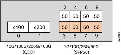
  • If a maximum of 200GE is configured on port 1, then ports 3, 5, 7, and 9 supports only 50GE, when 50GE is configured on ports 2, 4, 6, and 8.

    Figure 2. Restricted 50GE Support on Ports 3,5,7, and 9
    Restricted 50GE Support on Ports 3,5,7, and 9
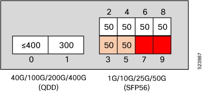
  • If a maximum of 300GE is configured on port 1, then:

    • Port 7 is disabled if 50GE is configured on port 6

    • Port 9 is disabled if 50GE is configured on port 8

    Figure 3. No Support on Ports 7 and 9
    Restricted 50GE Support on Ports 7 and 9
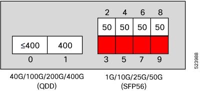
  • If maximum of 400GE is configured on port 1, then:

    • Port 3 is disabled if 50GE is configured on port 2

    • Port 5 is disabled if 50GE is configured on port 4

    • Port 7 is disabled if 50GE is configured on port 6

    • Port 9 is disabled if 50GE is configured on port 8

    Figure 4. No Support on Ports 3,5,7, and 9
    No Support on Ports 3,5,7, and 9

Using the negotiation auto command

When you configure the network interface speed using negotiation auto command, the speed is autonegotiated with the remote end interface. This command enhances the speed capability to 100M or 1G to be negotiated with the peer.

This sample configuration sets the interface speed to autonegotiate:


Note


The interface speed at remote end is set to 100Mbps.


Note


From Cisco IOS XR Software Release 7.3.2 onwards, autonegotiation is not enabled by default. Use the negotiation auto command to enable autonegotiation.


#configuration                              
 (config)#interface GigabitEthernet 0/0/0/31
 (config-if)#negotiation auto 
 (config-if)#commit
 (config-if)#end

Use the show controller GigE and show interface GigE commands to verify if the speed is autonegotiated:

#show interfaces GigabitEthernet 0/0/0/31 
GigabitEthernet0/0/0/31 is up, line protocol is up 
  Interface state transitions: 10
  Hardware is GigabitEthernet, address is 0035.1a00.e62c (bia 0035.1a00.e62c)
  Internet address is Unknown
  MTU 1514 bytes, BW 100000 Kbit (Max: 100000 Kbit)
     reliability 255/255, txload 0/255, rxload 0/255
  Encapsulation ARPA,
  Full-duplex, 100Mb/s, TFD, link type is autonegotiation
  output flow control is off, input flow control is off
  Carrier delay (up) is 10 msec
  loopback not set,
  Last link flapped 00:00:01
  Last input 00:00:00, output 00:00:00
  Last clearing of "show interface" counters never
  30 second input rate 1000 bits/sec, 1 packets/sec
  30 second output rate 0 bits/sec, 0 packets/sec
     91005 packets input, 11687850 bytes, 0 total input drops
     0 drops for unrecognized upper-level protocol
     Received 0 broadcast packets, 91005 multicast packets
              0 runts, 0 giants, 0 throttles, 0 parity
     0 input errors, 0 CRC, 0 frame, 0 overrun, 0 ignored, 0 abort
     61307 packets output, 4350024 bytes, 0 total output drops
     Output 0 broadcast packets, 8668 multicast packets
     0 output errors, 0 underruns, 0 applique, 0 resets
     0 output buffer failures, 0 output buffers swapped out
     15 carrier transitions

In the above show output you see that GigabitEthernet0/0/0/31 is up, and line protocol is up.

 #show controllers GigabitEthernet 0/0/0/31
Operational data for interface GigabitEthernet0/0/0/31:

State:
    Administrative state: enabled
    Operational state: Up
    LED state: Green On

Phy:
    Media type: Four-pair Category 5 UTP PHY, full duplex
    Optics:
        Vendor: CISCO
        Part number: SBCU-5740ARZ-CS1
        Serial number: AVC194525HW
        Wavelength: 0 nm
    Digital Optical Monitoring:
        Transceiver Temp: 0.000 C
        Transceiver Voltage: 0.000 V

        Alarms key: (H) Alarm high, (h) Warning high
                    (L) Alarm low, (l) Warning low
           Wavelength    Tx Power          Rx Power      Laser Bias
        Lane  (nm)    (dBm)    (mW)     (dBm)     (mW)      (mA)
        --   -----   ------   ------    ------   ------    ------
        0     n/a     0.0   1.0000     0.0   1.0000     0.000 

        DOM alarms:
            No alarms

        Alarm                     Alarm    Warning   Warning    Alarm
        Thresholds                High      High       Low       Low
                                 -------   -------   -------   -------
        Transceiver Temp (C):      0.000     0.000     0.000     0.000
        Transceiver Voltage (V):   0.000     0.000     0.000     0.000
        Laser Bias (mA):           0.000     0.000     0.000     0.000
        Transmit Power (mW):       1.000     1.000     1.000     1.000
        Transmit Power (dBm):      0.000     0.000     0.000     0.000
        Receive Power (mW):        1.000     1.000     1.000     1.000
        Receive Power (dBm):       0.000     0.000     0.000     0.000
    Statistics:
        FEC:
            Corrected Codeword Count: 0
            Uncorrected Codeword Count: 0

MAC address information:
    Operational address: 0035.1a00.e67c
    Burnt-in address: 0035.1a00.e62c
          
Autonegotiation enabled:
    No restricted parameters

Operational values:
    Speed: 100Mbps
    Duplex: Full Duplex
    Flowcontrol: None
    Loopback: None (or external)
    MTU: 1514
    MRU: 1514
    Forward error correction: Disabled

Using speed and negotiation auto command

When you configure the speed of the network interface (1G) using the speed and negotiation auto command, the interface autonegotiates all the paramets (full-duplex and pause) except speed. The speed is forced to the configured value.

This sample shows how to configures Gig interface speed to 100Mbps and autonegotiate other parameters:


Note


The interface speed at remote end is set to 100Mbps.


 #configuration                              
 (config)#interface GigabitEthernet 0/0/0/31
 (config-if)#negotiation auto 
 (config-if)#speed 100
 (config-if)#end

Use the show controller GigE and show interface GigE command to verify if the link is up, speed is forced to 100Mbps and autonegotiation is enabled:

#show interfaces GigabitEthernet 0/0/0/31
GigabitEthernet0/0/0/31 is up, line protocol is up 
  Interface state transitions: 9
  Hardware is GigabitEthernet, address is 0035.1a00.e62c (bia 0035.1a00.e62c)
  Internet address is Unknown
  MTU 1514 bytes, BW 100000 Kbit (Max: 100000 Kbit)
     reliability 255/255, txload 0/255, rxload 0/255
  Encapsulation ARPA,
  Full-duplex, 100Mb/s, TFD, link type is autonegotiation
  output flow control is off, input flow control is off
  Carrier delay (up) is 10 msec
  loopback not set,
  Last link flapped 00:00:03
  Last input 00:00:00, output 00:00:00
  Last clearing of "show interface" counters never
  30 second input rate 0 bits/sec, 1 packets/sec
  30 second output rate 0 bits/sec, 0 packets/sec
     90968 packets input, 11683189 bytes, 0 total input drops
     0 drops for unrecognized upper-level protocol
     Received 0 broadcast packets, 90968 multicast packets
              0 runts, 0 giants, 0 throttles, 0 parity
     0 input errors, 0 CRC, 0 frame, 0 overrun, 0 ignored, 0 abort
     61287 packets output, 4348541 bytes, 0 total output drops
     Output 0 broadcast packets, 8664 multicast packets
     0 output errors, 0 underruns, 0 applique, 0 resets
     0 output buffer failures, 0 output buffers swapped out
     12 carrier transitions


In the above show output you will observe that the GigabitEthernet0/0/0/31 is up, and line protocol is up This is because the speed at both ends is 100Mbps.

#show controllers GigabitEthernet 0/0/0/31
Operational data for interface GigabitEthernet0/0/0/31:

State:
    Administrative state: enabled
    Operational state: Up
    LED state: Green On

Phy:
    Media type: Four-pair Category 5 UTP PHY, full duplex
    Optics:
        Vendor: CISCO
        Part number: SBCU-5740ARZ-CS1
        Serial number: AVC194525HW
        Wavelength: 0 nm
    Digital Optical Monitoring:
        Transceiver Temp: 0.000 C
        Transceiver Voltage: 0.000 V

        Alarms key: (H) Alarm high, (h) Warning high
                    (L) Alarm low, (l) Warning low
           Wavelength    Tx Power          Rx Power      Laser Bias
        Lane  (nm)    (dBm)    (mW)     (dBm)     (mW)      (mA)
        --   -----   ------   ------    ------   ------    ------
        0     n/a     0.0   1.0000     0.0   1.0000     0.000 

        DOM alarms:
            No alarms

        Alarm                     Alarm    Warning   Warning    Alarm
        Thresholds                High      High       Low       Low
                                 -------   -------   -------   -------
        Transceiver Temp (C):      0.000     0.000     0.000     0.000
        Transceiver Voltage (V):   0.000     0.000     0.000     0.000
        Laser Bias (mA):           0.000     0.000     0.000     0.000
        Transmit Power (mW):       1.000     1.000     1.000     1.000
        Transmit Power (dBm):      0.000     0.000     0.000     0.000
        Receive Power (mW):        1.000     1.000     1.000     1.000
        Receive Power (dBm):       0.000     0.000     0.000     0.000
    Statistics:
        FEC:
            Corrected Codeword Count: 0
            Uncorrected Codeword Count: 0

MAC address information:
    Operational address: 0035.1a00.e67c
    Burnt-in address: 0035.1a00.e62c
          
Autonegotiation enabled:
    Speed restricted to: 100Mbps  /* autonegotiation is enabled and speed is forced to 100Mbps*/

Operational values:
    Speed: 100Mbps
    Duplex: Full Duplex
    Flowcontrol: None
    Loopback: None (or external)
    MTU: 1514
    MRU: 1514
    Forward error correction: Disabled

Ethernet MTU

The Ethernet maximum transmission unit (MTU) is the size of the largest frame, minus the 4-byte frame check sequence (FCS), that can be transmitted on the Ethernet network. Every physical network along the destination of a packet can have a different MTU.

Cisco IOS XR software supports two types of frame forwarding processes:

  • Fragmentation for IPV4 packets–In this process, IPv4 packets are fragmented as necessary to fit within the MTU of the next-hop physical network.


    Note


    IPv6 does not support fragmentation.


  • MTU discovery process determines largest packet size–This process is available for all IPV6 devices, and for originating IPv4 devices. In this process, the originating IP device determines the size of the largest IPv6 or IPV4 packet that can be sent without being fragmented. The largest packet is equal to the smallest MTU of any network between the IP source and the IP destination devices. If a packet is larger than the smallest MTU of all the networks in its path, that packet will be fragmented as necessary. This process ensures that the originating device does not send an IP packet that is too large.


Note


To enable hashing for L3 header only when the majority of traffic is fragmented, use the hw-module profile load-balance algorithm L3-Only command.


Jumbo frame support is automatically enable for frames that exceed the standard frame size. The default value is 1514 for standard frames and 1518 for 802.1Q tagged frames. These numbers exclude the 4-byte frame check sequence (FCS).

The following list describes the properties of MTUs:

  • Each physical port can have a different MTU.

  • Main interface of each bundle can have one MTU value.

  • L3 sub-interface (bundle or physical) shares MTU profiles and can have a maximum of 3 unique configured MTUs per NPU.


    Note


    L2 sub-interface MTU is not supported.


Link Layer Discovery Protocol (LLDP)

Cisco Discovery Protocol (CDP) is a device discovery protocol that runs over Layer 2. Layer 2 is also known as the data link layer that runs on all Cisco-manufactured devices, such as routers, bridges, access servers, and switches. CDP allows the network management applications to automatically discover and learn about other Cisco devices that connect to the network.

To support non-Cisco devices and to allow for interoperability between other devices, it also supports the IEEE 802.1AB LLDP. LLDP is also a neighbor discovery protocol that is used for network devices to advertise information about themselves to other devices on the network. This protocol runs over the data link layer, which allows two systems running different network layer protocols to learn about each other.

With LLDP, you can also access the information about a particular physical network connection. If you use a non-Cisco monitoring tool (via SNMP,) LLDP helps you identify the Object Identifiers (OIDs) that the system supports. The following are the supported OIDs:
  • 1.0.8802.1.1.2.1.4.1.1.4

  • 1.0.8802.1.1.2.1.4.1.1.5

  • 1.0.8802.1.1.2.1.4.1.1.6

  • 1.0.8802.1.1.2.1.4.1.1.7

  • 1.0.8802.1.1.2.1.4.1.1.8

  • 1.0.8802.1.1.2.1.4.1.1.9

  • 1.0.8802.1.1.2.1.4.1.1.10

  • 1.0.8802.1.1.2.1.4.1.1.11

  • 1.0.8802.1.1.2.1.4.1.1.12

Transmission of VLAN-Tagged LLDP Packets

Table 2. Feature History Table

Feature Name

Release

Description

Transmission of VLAN-Tagged LLDP Packets

Release 7.9.1

With this release, transmitting VLAN-tagged LLDP packets on the subinterfaces is supported. Earlier, if LLDP is enabled on a subinterface, the LLDP packets are sent without a VLAN tag.

VLAN-tagged LLDP packets help to identify unauthorized devices on the network and discover VLANs configured on the network devices. You can monitor and enforce VLAN segregation, ensuring that devices are connected to the correct VLANs and preventing unauthorized access to sensitive network segments.

You can enable VLAN tagging for LLDP packets globally or on each subinterface using these commands:

You can now transmit VLAN-tagged LLDP packets on the subinterfaces. When VLAN-tagged LLDP transmission is enabled either globally or at subinterface level, VLAN information is added to the Ethernet header of the constructed LLDP packet. For VLAN tagging, LLDP packet includes a TLV called the "Port VLAN ID TLV" to convey VLAN information. This TLV contains the VLAN ID associated with the port or interface of the sending device. It provides the receiving device with information about the VLAN membership of the transmitting port. With this, the devices can exchange VLAN information during LLDP discovery and facilitate the configuration and management of VLANs across the network.

Global VLAN-tagged LLDP Processing

You can enable VLAN tagging of LLDP packets globally on all subinterfaces after enabling LLDP on all subinterfaces.

When you enable LLDP globally, all subinterfaces are automatically enabled for both transmit and receive operations. You can override this default operation at the subinterface to disable receive or transmit operation.

The global attributes are available for LDDP under subinterface as well. See Enabling LLDP Globally for more details.

Subinterface-level VLAN-tagged LLDP Processing

Instead of enabling VLAN tagging of LLDP packets on all subinterfaces on the system, you can enable it only for specific subinterfaces. You can also disable either transmit or receive on the subinterface using lldp transmit disable or lldp receive disable commands.

Enabling LLDP Globally

To run LLDP on the router, you must enable it globally. When you enable LLDP globally, all interfaces that support LLDP are automatically enabled for both transmit and receive operations.

You can override this default operation at the interface to disable receive or transmit operations.

The following table describes the global attributes that you can configure:

Attribute Default Range Description
Holdtime 120 0-65535 Specifies the holdtime (in sec) that are sent in packets
Reinit 2 2-5 Delay (in sec) for LLDP initialization on any interface
Timer 30 5-65534 Specifies the rate at which LLDP packets are sent (in sec)

To enable LLDP globally, complete the following steps:

  1. RP/0/RP0/CPU0:router # configure

  2. RP/0/RP0/CPU0:router(config) #lldp

  3. end or commit

Running configuration

RP/0/RP0/CPU0:router-5#show run lldp
Fri Dec 15 20:36:49.132 UTC
lldp
!

RP/0/RP0/CPU0:router#show lldp neighbors
Fri Dec 15 20:29:53.763 UTC
Capability codes:
        (R) Router, (B) Bridge, (T) Telephone, (C) DOCSIS Cable Device
        (W) WLAN Access Point, (P) Repeater, (S) Station, (O) Other

Device ID       Local Intf          Hold-time  Capability     Port ID
SW-NOSTG-I11-PUB.cis Mg0/RP0/CPU0/0      120        N/A             Fa0/28

Total entries displayed: 1

RP/0/RP0/CPU0:router#show lldp neighbors mgmtEth 0/RP0/CPU0/0
Fri Dec 15 20:30:54.736 UTC
Capability codes:
        (R) Router, (B) Bridge, (T) Telephone, (C) DOCSIS Cable Device
        (W) WLAN Access Point, (P) Repeater, (S) Station, (O) Other

Device ID       Local Intf          Hold-time  Capability     Port ID
SW-NOSTG-I11-PUB.cis Mg0/RP0/CPU0/0      120        N/A             Fa0/28

Total entries displayed: 1

Enabling LLDP Per Interface

When you enable LLDP globally, all interfaces that support LLDP are automatically enabled for both transmit and receive operations. However, if you want to enable LLDP per interface, perform the following configuration steps:

  1. RP/0/RP0/CPU0:router(config)# int gigabitEthernet 0/2/0/0

  2. RP/0/RP0/CPU0:router(config-if)# no sh

  3. RP/0/RP0/CPU0:router(config-if)#commit

  4. RP/0/RP0/CPU0:router(config-if)#lldp ?

  5. RP/0/RP0/CPU0:router(config-if)#lldp enable

  6. RP/0/RP0/CPU0:router(config-if)#commit

Running configuration

RP/0/RP0/CPU0:router#sh running-config  
Wed Jun 27 12:40:21.274 IST
Building configuration...
!! IOS XR Configuration 0.0.0
!! Last configuration change at Wed Jun 27 00:59:29 2018 by UNKNOWN
!
interface GigabitEthernet0/0/0/0
 shutdown
!
interface GigabitEthernet0/0/0/1
 shutdown
!
interface GigabitEthernet0/0/0/2
 shutdown
!
interface GigabitEthernet0/0/0/3
 Shutdown
!
interface GigabitEthernet0/0/0/4
 shutdown
!
interface GigabitEthernet0/0/0/5
 shutdown
!
end

Verification

Verifying the config
==================
RP/0/RP0/CPU0:router#sh lldp interface <===== LLDP enabled only on GigEth0/0/0/3
Wed Jun 27 12:43:26.252 IST


GigabitEthernet0/0/0/3:
        Tx: enabled
        Rx: enabled
        Tx state: IDLE
        Rx state: WAIT FOR FRAME
RP/0/RP0/CPU0:router# 

RP/0/RP0/CPU0:router# show lldp neighbors 
Wed Jun 27 12:44:38.977 IST
Capability codes:
        (R) Router, (B) Bridge, (T) Telephone, (C) DOCSIS Cable Device
        (W) WLAN Access Point, (P) Repeater, (S) Station, (O) Other

Device ID       Local Intf          Hold-time  Capability     Port ID
ios             Gi0/0/0/3           120        R               Gi0/0/0/3       <====== LLDP enabled only on GigEth0/0/0/3 and neighborship seen for the same.

Total entries displayed: 1

RP/0/RP0/CPU0:router#

How to Configure Interfaces in Breakout Mode

Interface breakout allows you to divide a single high-bandwidth interface into multiple lower-bandwidth interfaces. This feature is useful for optimizing network performance and managing bandwidth allocation.

Table 3. Feature History Table

Feature name

Release Information

Feature Description

Breakout Port Support

Release 24.4.1

Introduced in this release on: Fixed Systems(8200, 8700); Modular Systems (8800 [LC ASIC: P100]) (select variants only*).

*This feature is now supported on:

  • 8212-32FH-M

  • 8711-32FH-M

  • 88-LC1-12TH24FH-E

8x25G Breakout Port Support on N540-24Q8L2DD-SYS

Release 24.2.11

This feature now extends support on the Cisco NCS 540 Series routers running on Cisco IOS XR7.

An 8x25G breakout interface allows you to split the 400G high-density ports into multiple lower-density ports.

You can now configure 8x25G breakout ports using the optics QDD-2X100-SR4-S.

Breakout port is supported on the following Cisco NCS 540 router variant:

  • N540-24Q8L2DD-SYS

Partial 4x100G and 2x100G Breakout Port Support

Release 7.11.1

A breakout interface allows to split the high-density port into multiple lower-density ports.

You can now configure 4x100G, 3x100G, 2x100G, and 1x100G for 400G breakout ports, and 2x100G, and 1x100G, for 200G breakout ports.

Breakout port is supported on the following Cisco NCS 540 router variant:

  • N540-24Q8L2DD-SYS

With breakout interfaces, you can eliminate the need for more network devices or modules.

Optimized Bandwidth Allocation for 3x100G Breakout

Release 7.11.1

Improved bandwidth allocation for 3x100G breakout by utilizing 300G bandwidth. Previously, 400G bandwidth was allocated for configuring 3x100G breakouts, resulting in 100G of unused bandwidth. This enhancement reduces unused bandwidth and optimizes overall bandwidth allocation.

Information About Breakout

The router supports transmission of traffic in the breakout mode. The breakout mode enables a physical port to be split into multiple GbE ports.

Breakout Mode options:

  • 4x10GbE

  • 4x25GbE

  • 8x25GbE

  • 4x100GbE

  • 3x100GbE

  • 2x100GbE

  • 1x100GbE

Table 4. Supported Breakout Modes

Port

Breakout Mode

Supported Optics

1/10/25GbE

4x10GbE

QSFP-40G-SR4

4x25GbE

QSFP-100G-SR4-S

400GbE

4x100GbE

QDD-4X100G-FR-S, QDD-4X100G-LR-S, QDD-400G-ZR-S, QDD-400G-ZRP-S, and DP04QSDD-HE0

3x100GbE, 1x100GbE, and 2x100GbE

QDD-400G-ZRP-S, and DP04QSDD-HE0

2x100GbE

QDD-2X100-SR4-S, QDD-2X100-CWDM4-S, and QDD-2X100-LR4-S

8x25GbE

QDD-2X100-SR4-S


Note


  • The supported breakout mode is dependent on the port and optic transceiver.


Configure Breakout in a Port


Note


For the N540-24Q8L2DD-SYS router, before proceeding with the breakout configuration, ensure that you configure the port mode speed under the optics controller. This step is crucial to ensure that the optics controller operates at the desired speed and can properly handle the breakout settings.

For port mode speed configuration steps, refer to Configure Port Mode Speed.


This example shows how to configuring a 4x100GbE breakout in a port:
RP/0/RP0/CPU0:Router# configure
RP/0/RP0/CPU0:Router(config)# controller optics 0/0/0/1
RP/0/RP0/CPU0:Router(config-Optics)# breakout 4x100
RP/0/RP0/CPU0:Router(config-Optics)# commit
RP/0/RP0/CPU0:Router(config-Optics)# end

This example shows how to configuring a 3x100GbE breakout in a port:

RP/0/RP0/CPU0:Router# configure
RP/0/RP0/CPU0:Router(config)# controller optics 0/0/0/1
RP/0/RP0/CPU0:Router(config-Optics)# breakout 3x100
RP/0/RP0/CPU0:Router(config-Optics)# commit
RP/0/RP0/CPU0:Router(config-Optics)# end
This example shows how to configuring a 8x25GbE breakout in a port:
RP/0/RP0/CPU0:Router# configure
RP/0/RP0/CPU0:Router(config)# controller optics 0/0/0/1
RP/0/RP0/CPU0:Router(config-Optics)# speed 200g
RP/0/RP0/CPU0:Router(config-Optics)# breakout 8x25
RP/0/RP0/CPU0:Router(config-Optics)# commit
RP/0/RP0/CPU0:Router(config-Optics)# end

Remove the Breakout Configuration

Removing the 4x100GbE breakout configuration:
RP/0/RP0/CPU0:Router# configure
RP/0/RP0/CPU0:Router(config)# controller optics 0/0/0/1
RP/0/RP0/CPU0:Router(config-Optics)# no breakout 4x100
RP/0/RP0/CPU0:Router(config-Optics)# commit
RP/0/RP0/CPU0:uut(config-Optics)# end

Verify a Breakout Configuration

Verifying a 4x100GbE breakout configuration:
RP/0/RP0/CPU0:Router# show running-config controller optics 0/0/0/1
controller Optics0/0/0/1
breakout 4x100
!
 
RP/0/RP0/CPU0:Router# show int br location 0/0/CPU0 | i HundredGigE0/0/0/1
       HundredGigE0/0/0/1/0          up          up          ARPA 10000   10000000
       HundredGigE0/0/0/1/1          up          up          ARPA 10000   10000000
Verifying a 3x100GbE breakout configuration:
RP/0/RP0/CPU0:Router# show controllers npu interface-bandwidth-usage detail instance 0 location 0/RP0/CPU0
Thu Oct 26 09:08:19.554 UTC
Interface Bandwidth usage
Total BW             : 1100 Gbps
Total BW used        : 300 Gbps
Total BW available   : 800 Gbps
Verifying a 8x25GbE breakout configuration:
RP/0/RP0/CPU0:Router# show running-config controller optics 0/0/0/0
controller Optics0/0/0/0
 speed 200g
 breakout 8x25
!

RP/0/RP0/CPU0:Router# show int br location 0/0/CPU0 | i TwentyFiveGigE0/0/0/0
Interface                      IP-Address        Status          Protocol Vrf-Name
TwentyFiveGigE0/0/0/0/0        unassigned        Down Down        default
TwentyFiveGigE0/0/0/0/1        unassigned        Down Down        default
TwentyFiveGigE0/0/0/0/2        unassigned        Down Down        default
TwentyFiveGigE0/0/0/0/3        unassigned        Down Down        default
TwentyFiveGigE0/0/0/0/4        unassigned        Down Down        default
TwentyFiveGigE0/0/0/0/5        unassigned        Down Down        default
TwentyFiveGigE0/0/0/0/6        unassigned        Down Down        default
TwentyFiveGigE0/0/0/0/7        unassigned        Down Down        default

Disable Auto-Squelching

Table 5. Feature History Table

Feature Name

Release Information

Description

Disable Auto-Squelching

Release 7.11.1

This release introduces support to disable Auto squelching. This helps to detect weak signals that are hidden within the laser source noise. By disabling Auto squelch, you can reduce the processing overhead in systems that have stable laser sources and minimal noise, helping you optimize the performance of your system. When the Auto squelch function is enabled, the optical module will generate a local fault signal on the host side if it detects a fault on the media side. By default, Auto squelch is enabled.

The feature introduces these changes:

CLI:The following keyword has been introduced.

YANG DATA models:

This release introduces the support to disable auto-squelch functionality on the module on the host side. When enabled, the squelch function is activated on the module when no suitable media-side input signal from the remote end is available to be forwarded to the host-side output (example: Rx LOS is asserted). Auto squelching is commonly used to suppress unwanted noise from laser sources in communication systems. When disabled and no valid signal is detected on the module from the remote end, the module will generate a local fault towards the NPU. However, disabling auto-squelching provides you with expanded signal detection. This enables you to detect extremely weak signals that are embedded within the laser source noise. Also, by eliminating the need to continuously monitor and suppress unwanted noise, system resources can be allocated more efficiently, leading to improved performance.

In this feature, we introduced the host auto-squelch disable command to disable the auto-squelch functionality when there is an invalid input signal from the remote end. This feature provides you with the flexibility to customize the system's behavior according to your requirements.

Disabling Laser Squelching Configuration Example

This example shows how to disable laser squelching for a host on controller optics:


router#config
router(config)#controller 0/0/0/0
router(config-Optics)#host auto-squelch disable
router(config-Optics)#commit 

Verification

This example shows how to verify the laser squelching disabled configuration:

router#show controllers optics 0/0/0/0 
    Host Squelch Status: disable