Site Planning Considerations
This chapter describes the general considerations for planning the installation of the Cisco NCS 6000 Series Routers.For complete instructions on mounting and securing the chassis, see the Cisco Network Convergence System 6000 Series Routers Unpacking, Moving, and Securing Guide .
- Basic Site and Installation Planning
- Aisle Spacing and Maintenance Access Floor Plan
- Power and Cooling Requirements
- System Console
- Cable Management
- Cisco Installation Services
- System Testing, Certification, and Warranties
Basic Site and Installation Planning
As you plan for basic site and installation requirements, consider the following:
-
Does the installation site have adequate power for the routing system?
-
Can the routing system be positioned close to the AC or DC power source, and are the power receptacles easy to reach?
-
Does the site have appropriate floor space available in which to install the rack-integrated chassis? See the “LCC Chassis Specifications” section or “FCC Chassis Specifications” section for more information.
-
Is there a scissor lift or similar lifting device available to lift the rack-integrated chassis?
In addition, make sure that the installation site meets the following access requirements:
-
At least 48 inches (122 cm) of clearance exist between rows of equipment. This space is needed to access components in the chassis. Additional clearance may be necessary for installation.
-
If a physical console terminal is desired near the system, make sure enough room exists for the console terminal and the console cable is long enough to reach the system from the terminal.
-
Chassis exhaust vents are not blocked, and input airflow at the bottom of the chassis is not blocked.
When planning the site, you should think about potential expansion of the system. Consider the following:
-
Expanding from a single-chassis standalone system to a multichassis system requires you to replace the original FCs with a different type of FC that has optical connectors for connecting the multiple chassis to each other. The LCC requires six S13 FCs for multi-chassis configurations. The FCC requires S2 FCs for multi-chassis configurations.
-
Floor space for additional chassis.
-
Proximity of chassis to each other.
-
Power and cooling requirements for additional chassis.
-
Cable management for routing system cables.
The following are required to move the Cisco NCS 6000 Series chassis at the site:
-
Moving device such as a safety hand truck, pallet jack, or forklift to move the equipment to the installation site. Make sure that the device is capable of preventing the chassis from tipping. For example, you could use a safety hand truck with retractable safety leg wheels and a security strap, such as the Stevens Appliance Truck Company “Escort” Model STEV SRT-M-66 (distributed by McMaster-Carr as Model 2654T6).
-
We recommend that you use the Cisco chassis lift dolly (“jumbo jack”) to move the chassis. The dolly product ID is: NCS 6008 Lift Dolly (PID NCS-LIFT). You can use this same dolly for both the Cisco NCS 6008 LCC and the Cisco NCS 6000 FCC. If you already have a CRS dolly, you can order PID NCS-LIFT-BRKT, which is the CRS Lift upgrade to NCS 6008 dolly.
Aisle Spacing and Maintenance Access Floor Plan
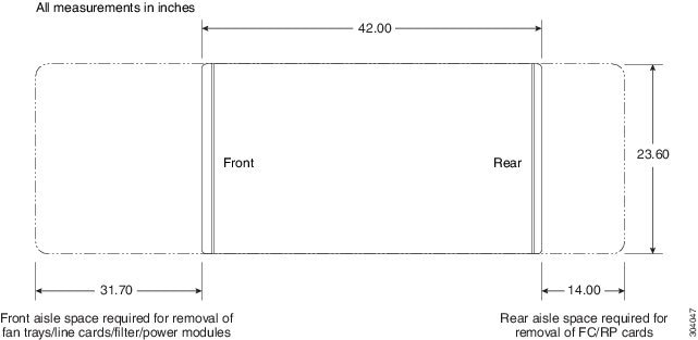
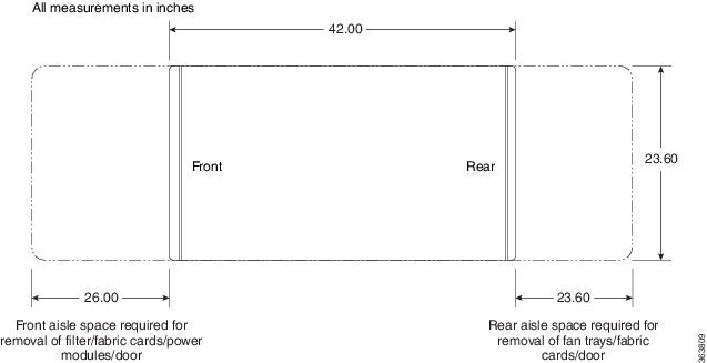
The floor plan for the Cisco NCS 6000 Series Routers must include enough space to install the chassis and allow sufficient airflow for the system. The floor plan must also provide enough room to access chassis components for maintenance (for example, to remove fan trays, power components, cables, and air filters).
The following figure shows a top-down view of the LCC footprint required for installation.

The following figure shows a top-down view of the FCC footprint required for installation.

Drill Hole Template
Before moving the chassis into place and securing it, you must make sure that your site is prepared. Because of its size and weight, the chassis must be securely bolted to the floor. Several possible bolting configurations exist for the chassis. Cisco provides a drill hole template to identify the chassis footprint and the pattern of holes that must be drilled into the floor for the mounting hardware that secures the chassis to the floor.
Power and Cooling Requirements
See the Power and Cooling chapter for information about the power and cooling systems on the chassis and for information about the power and cooling requirements at the installation site.
System Console
A system console is required to configure the routing system for operation. As you plan your site facilities, make sure that the site has enough room for a system console and the console cable is long enough to reach the routing system.
 Note | The console port does not support modem control or hardware flow control. The port requires a straight-through EIA/TIA-232 cable. |
Cable Management
As the size of the routing system increases, the cabling required for the chassis increases. For example, a chassis fully loaded with eight line cards (LCs) or 12 fabric cards (FCs) has more cables connected to it than a partially loaded chassis.
The cabling runs must be carefully planned. The basic configurations for various routing systems should be arranged to minimize the complexity and length of the cable runs. Precut and terminated cables are considered part of the basic configuration.
The four cable management brackets on the Cisco NCS 6000 chassis are for organizing these interface cables to keep the front and rear of the chassis clear and to help eliminate sharp bends in the cables. Excessive bending can damage interface cables.
You must provide the cables from the Cisco NCS 6000 chassis to your facility interconnect. Because the type and number of components vary with each routing system site, plan these data cable runs in advance of the system installation. When planning the data cable runs, consider the following:
-
Number and type of interface connections
-
Vertical cable management
-
Proper length and termination of cables
-
Termination at the other end of the cables (patch panel, optical transport equipment, and so on)
 Note | For the LCC, contact your Cisco representative to obtain a Cisco short-reach, 100x10GE patch panel (PID NCS-PP-100X10-SR). |
 Note | An optional but helpful insertion-extraction tool (IET) available from manufacturer Ripley Miller (part number 80860), can be used to expedite insertion and extraction of the fiber optic connectors in high-density patch panels. |
Required Cables
See the RP Card Cables for the LCC table for the types of cables required to connect to the ports on the RP cards in the LCC. See the SC and SC-SW Card Cables for the FCC table for the types of cables required to connect to the ports on the SC and SC-SW cards in the FCC.
|
RP Card Port |
Required Cable Type |
|---|---|
|
Console port 0 |
RJ-45 port for straight-through EIA/TIA-232 cable. |
|
Console port 1 |
RJ-45 port for straight-through EIA/TIA-232 cable. |
|
Console port 2 |
RJ-45 port for straight-through EIA/TIA-232 cable. |
|
Ethernet management port 0 |
RJ-45 port for shielded twisted-pair (STP) cable Cat5e or better. |
|
Ethernet management port 1 |
Port for SFP+ optical module capable of up to 10-Gbps operation. For example: copper SFP-GE-T, 1GE SFP-GE-L, SFP-GE-S, 10G-SFP-SR and 10G-SFP-LR |
|
Control plane expansion Ethernet port 0 |
Port for SFP+ optical module capable of up to 10-Gbps operation. |
|
Control plane expansion Ethernet port 1 |
Port for SFP+ optical module capable of up to 10-Gbps operation. |
|
Six interface shelf Ethernet ports |
Port for SFP+ optical module capable of up to 10-Gbps operation. |
|
Sync port for external BITS clock |
Cat5 or better unshielded twisted-pair (UTP) cable. |
|
Sync port 0 for BITS/J.211 time reference input |
RJ-45 for STP cable Cat5 or better. |
|
Sync port 1 for BITS/J.211 time reference input |
RJ-45 for STP cable Cat5 or better. |
|
GPS Time Transfer Interface (TTI) port |
RJ-45 port for STP cable Cat5 or better, RF 1.0/2.3 coax connectors. |
|
Cisco Time Expansion port |
RJ-45 port for STP cable Cat5 or better. |
|
IEEE 1588 time synchronization port |
RJ-45 port for STP cable Cat5 or better. |
|
USB 2.0 port for external storage |
— |
|
Alarm port |
Shielded 15-pin D-SUB cable with male connector. |
|
SC and SC-SW Card Ports |
Required Cable Type |
|---|---|
|
Console port 0 |
RJ-45 port for straight-through EIA/TIA-232 cable. |
|
Console port 1 |
RJ-45 port for straight-through EIA/TIA-232 cable. |
|
RJ-45 Ethernet management port |
RJ-45 port for shielded twisted-pair (STP) cable Cat5e or better. |
|
Control plane expansion Ethernet port 0 |
Port for SFP+ optical module capable of up to 10-Gbps operation. |
|
Control plane expansion Ethernet port 1 |
Port for SFP+ optical module capable of up to 10-Gbps operation. |
|
Up to 56 SFP+ 10GE optical ports, depending on the multi-chassis configuration1 |
Port for SFP+ optical module capable of up to 10-Gbps operation. |
|
QSFP+ 40GE optical ports (two per SC-SW card)1 |
Port for QSFP+ 40GE optical module capable of up to 40-Gbps operation. |
|
USB 2.0 port for external storage |
— |
|
Alarm port |
Shielded 15-pin D-SUB cable with male connector. |
Cisco Installation Services
Cisco or a Cisco partner can provide complete installation services, from planning to power up. For information about Cisco or Cisco partner installation services, see Cisco Services at: http://www.cisco.com/web/services/index.html
System Testing, Certification, and Warranties
After the routing system has been installed, it must be tested and certified.
-
For information about testing and certification, refer to the product datasheets at: http://www.cisco.com/c/en/us/products/routers/network-convergence-system-6000-series-routers/datasheet-listing.html
-
For product warranty information, see: http://www.cisco.com/c/en/us/products/warranty-listing.html
 Feedback