Overview
This chapter provides an overview of the Cisco NCS 6000 Series Routers. The Cisco NCS 6000 Series Routers include the Cisco NCS 6008 Line Chassis (LCC) and the Cisco NCS 6000 Fabric Card Chassis (FCC). Read the information in this chapter before you unpack and transport the chassis to the final installation location.
Chassis Packaging
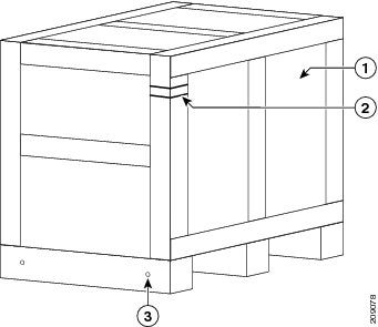
Depending on the number of options that you ordered, the Cisco NCS 6000 Series chassis arrives packaged in several shipping crates and pallets. The chassis is shipped on a pallet by itself and arrives inside a polyethylene bag enclosed in a plywood box, held in place by steel clips. Other system components are shipped in separate crates and can arrive at the final chassis site at different times.
For complete details on the contents of your shipment, see the inventory and parts identification label on the crate. The total number of pallets depend on the details of the options that you ordered, with each package containing a label that describes the contents.
 Note | The following list is only a sample of what a Cisco NCS 6000 shipment contains. For complete details on the contents of each pallet, see the shipping and parts identification label on the pallet or the shipping manifest. |
-
Dolly pallet: Contains two dolly units in the 90-degree position (Figure 3).
-
Chassis pallet: Contains the chassis itself encased in a polyethylene bag and covered with a wooden packing crate held together with metal brackets. The chassis is the first shipping box to be unpacked and transported to its final installation location.
The drill hole template (Cisco product ID NC6-DRILLTEMP) is attached to the inside of the shipping crate door. The drill hole template is the same for both the LCC and FCC.
-
Power components pallet: Contains the power components, including the Power Modules (PMs). For the FCC, a separate box ships that contains a power supply enclosure that includes the power trays and the PCMs.
-
Primary card pallet: Contains the fabric cards, line cards, and route processor cards. The FCC pallet contains only fabric cards.
-
Cosmetics pallet: Contains the default cosmetic components for the exterior of the chassis. This pallet will also contain any optional cosmetic components for the exterior of the chassis, if ordered.
Chassis Specifications
The following table lists the physical specifications (dimensions and weight) for the Cisco NCS 6000 Series Routers (as shipped and as installed without packaging).
|
Cisco NCS 6008 Line Card Chassis |
Cisco NCS 6000 Fabric Card Chassis |
|
|---|---|---|
|
Physical Dimensions (Without Packaging) |
||
|
Height |
81.0 in. (205.7 cm) as shipped 84.0 in. (213.4 cm) as installed with the “top cap” (The top cap in the cosmetics package attaches to the top of the chassis) |
76.60 in. (205.7 cm) as shipped 84.0 in. (213.4 cm) as installed with the power shelf The FCC does not have a top cap. |
|
Width |
23.6 in. (59.9 cm) |
23.6 in. (59.9 cm) |
|
Depth |
39.0 in. (99.1 cm) without doors and other cosmetics 42.0 in. (106.7 cm) with front and rear doors and standard vertical cable troughs |
39.0 in. (99.1 cm) without exterior cosmetics 42.0 in. (106.7 cm) with front and rear doors and standard vertical cable troughs |
|
Aisle Spacing |
To install the LCC (front): 48 in. (122 cm) To service FRUs (front): 31.7 in. (80.5 cm) To service FRUs (rear): 14.0 in. (35.6 cm) |
To install the FCC (front): 48 in. (122 cm) To service FRUs (front): 31.7 in. (80.5 cm) To service FRUs (rear): 14.0 in. (35.6 cm) |
|
Weight (Without Packaging) |
||
|
775 lb (352 kg) chassis as shipped 1025 lb (466 kg) chassis in shipping crate with pallet 1450 lb (658 kg) chassis fully loaded with power, fan trays, cards, and cosmetics |
708 lb (321 kg) chassis as shipped 925 lb (420 kg) chassis in shipping crate with pallet 1130 lb (513 kg) chassis fully loaded with power, fan trays, cards, and cosmetics |
|
Safety Guidelines
 Caution | Before you perform any procedure in this document, review the safety guidelines in this section to avoid injuring yourself or damaging the equipment. |
The following guidelines are for your safety and to protect equipment. Guidelines do not include all hazards. Be alert.
 Note | Before installing, configuring, or troubleshooting any installed card, review the safety warnings listed in the Regulatory Compliance and Safety Information for the Cisco Network Convergence System 6000 Series Routers. |
Never attempt to lift an object that might be too heavy for you to lift by yourself.
-
Keep the work area clear and dust free during and after installation. Do not allow dirt or debris to enter into any laser-based components.
-
Keep tools and chassis components away from walk areas.
-
Do not wear loose clothing, jewelry, and other items that could get caught in the chassis while working with the chassis and its associated components.
-
Use Cisco equipment in accordance with its specifications and product-usage instructions.
-
Do not work alone if potentially hazardous conditions exist.
Preventing Electrostatic Discharge
Electrostatic discharge (ESD) damage, which can occur when electronic cards or components are improperly handled, results in complete or intermittent failures. We recommend use of an ESD-preventive strap whenever you handle network equipment or one of its components.
Follow these guidelines for preventing ESD damage:
-
Always use an ESD-preventive wrist or ankle strap, and ensure that it makes good skin contact. Connect the equipment end of the connection cord to an ESD jack or bare metal surface on the chassis.
-
Handle a card by its ejector levers, when applicable, or its metal carrier only; avoid touching the board or connector pins.
-
Place a removed card board side up on an antistatic surface or in a static-shielding bag. If you plan to return the component to the factory, immediately place it in a static-shielding bag.
-
Avoid contact between the card and clothing. The wrist strap protects the board from only ESD voltage on the body: ESD voltage on clothing can still cause damage.
 Caution | When unpacking and setting parts aside, it is important to set them either in their original antistatic packaging or on an antistatic mat to avoid ESD damage. |
Site Preparation
Before moving the chassis into place and securing it, you must make sure that your site is prepared. Verify that the securing location provides the recommended space and ensure that you have enough space available for installation and maintenance of the chassis and its components.
For additional details on making your site ready for the chassis, see the Cisco Network Convergence System 6000 Series Routers Site Planning Guide .
System Installation Templates
Because of its size and weight, the chassis must be securely bolted to the floor. Cisco provides a drill hole template (Figure 1) that ships attached to the inside of the crate door. This template identifies the chassis footprint and the pattern of holes that must be drilled into the floor for the mounting hardware that secures the chassis to the floor. This drill template is used for both the LCC and FCC.
For more information about floor plans, clearance information, and planning for future space needs, see the Cisco Network Convergence System 6000 Series Routers Site Planning Guide.

|
1 |
Cable pass though |
4 |
Secondary LCC mount locations |
|
2 |
Cable pass through for chassis ground |
5 |
Secondary FCC mount locations |
|
3 |
Primary LCC/FCC mount locations (preferred location) |
|
|
Dolly Specifications
The optional dolly that is available for the Cisco NCS 6000 Series chassis is flexible enough to meet several challenges common when first positioning a chassis of this size and weight. Such challenges include limited hallway or doorway width, doorway thresholds, ramps, and tight corners along the transport route. To overcome these challenges, use the dolly in either of the following configurations:
-
The 90-degree configuration — The dolly assemblies are shipped in this configuration. In some cases, this configuration is needed to transport the chassis. Use the 90-degree configuration (Figure 5) to move the chassis off the pallet. Take extra care when using this configuration so that the chassis does not tip too far and fall during transport.
-
This 180-degree configuration — This configuration is a more stable configuration for transporting the chassis. We recommend using the 180-degree configuration (Figure 6) for moving the chassis, although both configurations are acceptable to transport the as-shipped chassis.
 Note | The optional Cisco NCS 6000 Series Routers lift dolly is available from Cisco (PID NCS-LIFT). If you already have a CRS lift dolly, you can order PID NCS-LIFT-BRKT, which is the CRS lift upgrade to the NCS lift dolly. |
The following table lists the specifications for the Cisco NCS 6000 Series chassis lift dolly.
|
Specification |
Value |
|---|---|
|
Weight (each component) |
126.0 lb (57 kg) |
|
Maximum recommended safe curb height |
1.5 in. (3.8 cm) |
Unpacking the Dolly
We recommend that you use a dolly to move the chassis. The dolly is an optional item that you can order from Cisco. The shipping crate contains the dolly units, positioned in the 90-degree configuration (Figure 3). This section describes how to unpack and position the dolly units.
 Note | If the dolly supplied by Cisco is not the appropriate method of transportation, contact Cisco support to determine a method of transportation appropriate for your site. Ensure that the alternate moving device is capable of supporting the weight of the chassis, moving the chassis safely, and preventing the chassis from tipping too far and falling during transport. |
Required Tools and Equipment
-
3/8-inch ratchet wrench
-
5/8-inch socket
-
Flat-blade screwdriver
Steps
| Step 1 | Carefully move the pallet containing the dolly to the location where you plan to unpack it. The dolly arrives as two separate, identical units, one unit each for the front and back of the chassis. | ||||||||||||||||||||||||||||||||||||||||||
| Step 2 | Use the
flat-blade screwdriver to remove the clip from the dolly shipping crate.
| ||||||||||||||||||||||||||||||||||||||||||
| Step 3 | Remove the front panel from the dolly crate. Swing open and lift off. | ||||||||||||||||||||||||||||||||||||||||||
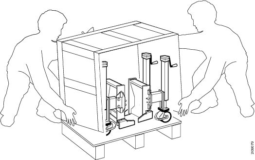
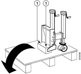
| Step 4 | Using the 3/8-inch ratchet wrench with 5/8-inch socket, remove the two holding bolts from each side at the base of the dolly pallet (Figure 2). | ||||||||||||||||||||||||||||||||||||||||||
| Step 5 | With at least
two people, one on each side of the dolly shipping crate, tilt the crate back
and lift off the pallet.
 | ||||||||||||||||||||||||||||||||||||||||||
| Step 6 | Using the
3/8-inch ratchet wrench with 5/8-inch socket, remove the two bolts and the
dolly stopper.
| ||||||||||||||||||||||||||||||||||||||||||
| Step 7 | Release the
caster brakes and remove the dolly from the pallet.
The following figure shows the dolly 90-degree configuration labels and components. 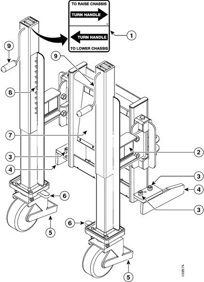
The following figure shows the dolly 180-degree configuration. Both dolly units are identical. 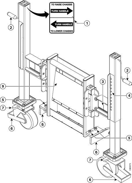
|
Modifying the Dolly Configuration
The dolly can be positioned in either the 180-degree or 90-degree configuration, depending on the needs of your site. See the Guidelines for important recommendations before modifying the dolly configuration.
When changing the configuration of the dolly wheel assemblies (from 180 to 90 degrees or conversely), follow these guidelines:
-
Lower the chassis to the floor before you change configurations.
-
Keep the casters on the floor at all times when you are changing the dolly configuration from one position to the other.
-
Unlock the brake or anti-rotation on the casters only when you are ready to actually change the configuration (move the lift swing arm bracket). When you are preparing to change the configuration (remove bolts), make sure that the brakes and anti-rotation pin are in the locked position.
-
Change the dolly configuration one caster at a time. Take your time and do not rush through the process.
-
Make sure that the bolts are secured after you have completed changing the configuration.
Required Tools and Equipment
-
3/8-inch ratchet wrench
-
12-mm hex bit
Steps
To change the dolly configuration from the as-shipped 90-degree configuration to the 180-degree transport configuration, perform the following steps.
| Step 1 | Set the caster wheel rotation using the caster anti-rotation pin. Turn the anti-rotation pin to a vertical position to lock the caster (Figure 5, callout 2). | ||
| Step 2 | To lock the brakes depress the brakes on each side of the dolly. | ||
| Step 3 | Using the handles (Figure 5, callout 9), turn the dolly lifting cranks to raise or lower the dolly according to the label rotation direction. Turn the lifting cranks until the dolly casters are just off the floor. | ||
| Step 4 | Unlock the dolly caster brakes and anti-rotation pins on both units. | ||
| Step 5 | On the dolly
unit attached to the front side of the chassis, use the 3/8-inch ratchet wrench
with 12-mm hex bit to remove the two holding bolts on the left side lift arm
swing bracket to convert to the 180-degree configuration.
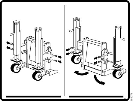 | ||
| Step 6 | Swing the lift arm swing bracket to the side (180-degree position as shown in the above figure). Reinsert the holding bolts and partially tighten the bolts. | ||
| Step 7 | Repeat Step 1 through Step 6 for the other dolly unit. Figure 6 shows the dolly in a 180-degree configuration. | ||
| Step 8 | Lock the dolly caster brakes and anti-rotation pins until you are ready to move the chassis. | ||
| Step 9 | Using the
3/8-inch ratchet wrench with 12-mm hex bit, firmly tighten the holding bolts on
both dolly units.
|
 Feedback