- Preface
- Product Overview
- Administration Tasks for Internal Directory Mode
- Administration Tasks for External Directory Mode
- Directory Administration Tool
- Cisco PIX Firewall Device Support
- IMGW Device Module Development Toolkit
- Troubleshooting
- How to Use the IMGW Device Module Toolkit
- Software Licenses and Acknowlegements
- Levels of Access
- How to Login and Out of the System
- Operator-Level Operations
- Administrator-Level Operations
Administration Tasks for Internal Directory Mode
This chapter describes the Cisco CNS Configuration Engine 1.4 administration tasks for Internal Directory mode including information about:
•![]() How to Login and Out of the System
How to Login and Out of the System
•![]() Device Configuration Order Entry
Device Configuration Order Entry
•![]() Redefining Hostname, Domain Name, and Country Code
Redefining Hostname, Domain Name, and Country Code
Levels of Access
In Internal Directory mode, there are two categories of users who have access to device information:
•![]() Administrator
Administrator
•![]() Operator
Operator
An Administrator has the higher access level of the two categories; full access to device and user information. An Operator has access to only order entry and operator password-related tasks.
For example, an Administrator can access all the functional areas of the user interface. Whereas, an Operator only has access to Order Entry and Tools functions.
How to Login and Out of the System
You can connect to the system by means of:
•![]() SSH
SSH
•![]() System console
System console
How to Login
To login to the system, follow these steps:
Step 1 ![]() Launch your web browser.
Launch your web browser.
This user interface is best viewed using Microsoft Internet Explorer, version 5.5 or later.
Step 2 ![]() Go to the Cisco CNS Configuration Engine 1.4 URL.
Go to the Cisco CNS Configuration Engine 1.4 URL.
For example: http://<ip_address>

Note ![]() If encryption is set during Setup (see "Encryption Settings" section on page 2-6), use https://<ip_address>.
If encryption is set during Setup (see "Encryption Settings" section on page 2-6), use https://<ip_address>.
The login window appears (see Figure 2-1).
Figure 2-1 Logging In to the Configuration Server

Step 3 ![]() Enter your User ID.
Enter your User ID.
This is the value for the ConfigService AdminID parameter that you entered during Setup.
Step 4 ![]() Enter your password.
Enter your password.
Step 5 ![]() Click LOGIN.
Click LOGIN.
For an Administrator, the full-function Cisco CNS Configuration Engine 1.4 Home page appears (see Figure 2-2).
For an Operator, a limited-function Cisco CNS Configuration Engine 1.4 Home page appears where the active tabs are Home, Order Entry, and Tools (see Figure 2-3).
Figure 2-2 Administrator Home Page

Figure 2-3 Operator Home Page

How to Log Out
To log out of the system, click the Logout button.
Operator-Level Operations
After logging into the Cisco CNS Configuration Engine 1.4, an Operator has access to the following functions:
•![]() Order Entry
Order Entry
–![]() New Order
New Order
–![]() Edit Order
Edit Order
–![]() Subdevice Order
Subdevice Order
–![]() Update Image
Update Image
–![]() Query Device Inventory
Query Device Inventory
•![]() Tools
Tools
–![]() Change Password
Change Password
–![]() View Event Log
View Event Log
–![]() View Image Server Log
View Image Server Log
•![]() Image Service
Image Service
–![]() View Image
View Image
–![]() Query Job
Query Job
–![]() Cancel/Stop Job
Cancel/Stop Job
–![]() Restart Job
Restart Job
Device Configuration Order Entry
The order entry functions of creating a new device configuration order, editing an existing order, and managing subdevice orders are available to both Administrator and Operator.
To conduct device configuration order entry operations as an Operator, follow these steps:
Step 1 ![]() From the Home page, click Order Entry.
From the Home page, click Order Entry.
The Order Entry page appears (see Figure 2-4).
Step 2 ![]() To add and edit device configuration orders, see "Device Configuration Order Entry" section.
To add and edit device configuration orders, see "Device Configuration Order Entry" section.
Figure 2-4 Order Entry for Operator-Level User

How to Change or Reset a Password at the Operator Level
Under tools, an Operator has access to the password editor (for changing or resetting only their own password), and the event log.
To change or reset a password at the operator level, click Tools.
The password editor appears (see Figure 2-5).
Figure 2-5 Operator Password Editor

Step 1 ![]() Enter your old password.
Enter your old password.
Table 2-1 lists valid values for these fields.
Step 2 ![]() Enter your new password.
Enter your new password.
Step 3 ![]() To confirm your new password, enter it again.
To confirm your new password, enter it again.
Step 4 ![]() To save your changes, click Save.
To save your changes, click Save.
Step 5 ![]() To return to the Tools main menu, click the Tools tab.
To return to the Tools main menu, click the Tools tab.
How to View the Event Log
As an operator, to view the Event Log, click Tools -> View Event Log.
The Event Log control panel appears (see Figure 2-6)
Figure 2-6 Operator-Level Event Log Control Panel

CNS Image Service
Under Image Service, an Operator can view available images (see "How to View an Image" section) and perform tasks on image update operations the same as an administrator (see "Working with Image Update Jobs" section).
Administrator-Level Operations
In Internal Directory mode, an Administrator can access all of the functions provided by the Cisco CNS Configuration Engine 1.4 user interface including managing user accounts and devices.
Managing Devices
To begin managing devices, follow these steps:
Step 1 ![]() Login to the system (see "How to Login and Out of the System" section).
Login to the system (see "How to Login and Out of the System" section).
Step 2 ![]() From the Home page, click on the Devices tab.
From the Home page, click on the Devices tab.
A functional overview of the device administration options appears (see Figure 2-7).
Figure 2-7 Device Administration Overview

How to View Device Configuration
To view a device configuration, follow these steps:
Step 1 ![]() From the Devices Functional Overview page, click View Device.
From the Devices Functional Overview page, click View Device.
The Device List page appears (see Figure 2-8).
Figure 2-8 View Device List

Step 2 ![]() Click on the icon for the device configuration you wish to view.
Click on the icon for the device configuration you wish to view.
The Configuration for that device appears (see Figure 2-9).
Figure 2-9 Device Configuration

Note ![]() The device configuration displayed is the configuration as it appears at the configuration server. It may not be the configuration running on the device.
The device configuration displayed is the configuration as it appears at the configuration server. It may not be the configuration running on the device.
Step 3 ![]() To view subdevices (if applicable), in the left pane, click View Subdevices.
To view subdevices (if applicable), in the left pane, click View Subdevices.
Step 4 ![]() To view Images associated with this device (if applicable), in the left pane, click View Images.
To view Images associated with this device (if applicable), in the left pane, click View Images.
Step 5 ![]() To return to the Devices main menu, click on the Devices tab.
To return to the Devices main menu, click on the Devices tab.
How to Add a Device
To add the logical appearance of a device to the configuration server, follow these steps:
Step 1 ![]() From the Devices Functional Overview page, click Add Device.
From the Devices Functional Overview page, click Add Device.
The Device Information page appears (see Figure 2-10).
Figure 2-10 Device Information Page

Step 2 ![]() Enter a valid value (no spaces) in the Device Name field.
Enter a valid value (no spaces) in the Device Name field.
Table 2-3 list valid values for these attributes.
Step 3 ![]() In the Unique ID field, accept the default value that appears or enter another valid value (no spaces).
In the Unique ID field, accept the default value that appears or enter another valid value (no spaces).
Step 4 ![]() Select a device type from the drop-down list.
Select a device type from the drop-down list.
Step 5 ![]() Choose a template file.
Choose a template file.
To use a template on your Cisco CNS Configuration Engine 1.4:
a. ![]() Choose Select file.
Choose Select file.
b. ![]() Use the drop-down list to choose a template.
Use the drop-down list to choose a template.
OR
To use an external template:
a. ![]() Choose Enter URL.
Choose Enter URL.
b. ![]() Enter the full URL for the server, directory, and filename where the template is stored. Currently, only http is supported.
Enter the full URL for the server, directory, and filename where the template is stored. Currently, only http is supported.
c. ![]() To test access to the external template, click Test URL.
To test access to the external template, click Test URL.
If the server is unavailable or the external template cannot be accessed, an error appears. You can still save this logical device, but the template is not available until you have access to the external template.
Step 6 ![]() Choose a group.
Choose a group.

Tip ![]() Use the Group Manager under DAT (see "How to Add a Group" section) to set up groups before you add a device.
Use the Group Manager under DAT (see "How to Add a Group" section) to set up groups before you add a device.
Step 7 ![]() To cancel creating a device and return to the Devices main menu, click Cancel.
To cancel creating a device and return to the Devices main menu, click Cancel.
Step 8 ![]() To return to the Devices main menu and cancel creating a device, click on the Devices tab.
To return to the Devices main menu and cancel creating a device, click on the Devices tab.
Step 9 ![]() To continue creating IDs for this device, click Next.
To continue creating IDs for this device, click Next.
If the Device Type is not Pix, the Create Device page for adding device IDs appears (see Figure 2-12).
If the Device Type is Pix, the Pix Password page appears (see Figure 2-11).
Step 10 ![]() If applicable, enter an authentication password for Pix device, otherwise skip to Step 11.
If applicable, enter an authentication password for Pix device, otherwise skip to Step 11.
Figure 2-11 Pix Password Page

Figure 2-12 Device IDs Page

Step 11 ![]() For the Event ID, accept the default value that appears or enter another value.
For the Event ID, accept the default value that appears or enter another value.
Table 2-5 list valid values for these attributes.
Step 12 ![]() For the Config ID, accept the default value that appears or enter another value.
For the Config ID, accept the default value that appears or enter another value.
Step 13 ![]() For the Image ID, if you are using configuration service only, leave this field blank.
For the Image ID, if you are using configuration service only, leave this field blank.
To use image service this parameter must be specified.
Step 14 ![]() To cancel creating a device and return to the Devices main menu, click Cancel.
To cancel creating a device and return to the Devices main menu, click Cancel.
Step 15 ![]() If applicable (modular router), choose subdevices.
If applicable (modular router), choose subdevices.
Step 16 ![]() To go back to the previous page, click Back.
To go back to the previous page, click Back.
Step 17 ![]() To finish creating this device at this point, click Finish.
To finish creating this device at this point, click Finish.
Step 18 ![]() To continue creating Image associations for this device, click Next.
To continue creating Image associations for this device, click Next.
The Create Device page for adding Image associations appears (see Figure 2-13).
Figure 2-13 Create Device Image Association

Step 19 ![]() In Step 3 on the page, select the image from the Name drop-down list.
In Step 3 on the page, select the image from the Name drop-down list.
The Image Type field and Image Location drop-down box are populated with corresponding information for the image.
Step 20 ![]() From the Image Location drop-down list, select the desired location.
From the Image Location drop-down list, select the desired location.
Step 21 ![]() To add another row for image location, click Add Another Row.
To add another row for image location, click Add Another Row.
You can locate multiple copies of an image on separate servers. This allows you to do load-sharing when updating a large number of devices. Each device in a large group can be associated with a copy of the image located at one of many server locations.
Step 22 ![]() In the Destination field, enter a valid URL where the image will be copied.
In the Destination field, enter a valid URL where the image will be copied.
For example:
disk0:/c7200-mz
Step 23 ![]() To indicate which image is to be activated on the device after distribution, select the radio button in front of each row.
To indicate which image is to be activated on the device after distribution, select the radio button in front of each row.
Step 24 ![]() In Step 4, on the page, select the Configuration Control template file you want to send to this device for activation of a new image:
In Step 4, on the page, select the Configuration Control template file you want to send to this device for activation of a new image:
Tip ![]() Use the Configuration Control template that contains the CLI commands required for image activation for this device (see "Configuration Control Template" section). If you do not have such a template, see "How to Add a Template" section.
Use the Configuration Control template that contains the CLI commands required for image activation for this device (see "Configuration Control Template" section). If you do not have such a template, see "How to Add a Template" section.
a. ![]() To select a template file from the drop-down list, click the Select file radio button.
To select a template file from the drop-down list, click the Select file radio button.
b. ![]() Use the drop-down list to choose a template file.
Use the drop-down list to choose a template file.
OR
To use an external template:
a. ![]() Choose Enter URL.
Choose Enter URL.
b. ![]() Enter the full URL for the server, directory, and filename where the template is stored. Currently, only http is supported.
Enter the full URL for the server, directory, and filename where the template is stored. Currently, only http is supported.
c. ![]() To test access to the external template, click Test URL.
To test access to the external template, click Test URL.
If the server is unavailable or the external template cannot be accessed, an error appears. You can still save this logical device, but the template is not available until you have access to the external template.
Step 25 ![]() To cancel creating a device and return to the Devices main menu, click Cancel.
To cancel creating a device and return to the Devices main menu, click Cancel.
Step 26 ![]() To go back to the previous page, click Back.
To go back to the previous page, click Back.
Step 27 ![]() To finish creating this device, click Finish.
To finish creating this device, click Finish.
How to Edit a Device
To edit information associated with a particular device, follow these steps:
Step 1 ![]() From the Devices Functional Overview page, click Edit Device.
From the Devices Functional Overview page, click Edit Device.
Step 2 ![]() From the Edit Device page, click on the icon for the device you wish to edit.
From the Edit Device page, click on the icon for the device you wish to edit.
The device configuration appears with a menu of edit functions in the left pane (see Figure 2-14).
Figure 2-14 Device Configuration
Step 3 ![]() From the left pane, choose the edit function you want to use.
From the left pane, choose the edit function you want to use.
Step 4 ![]() To go back to the Device List page, in the left pane, click << Up.
To go back to the Device List page, in the left pane, click << Up.
Step 5 ![]() To return to the Devices main menu, click on the Devices tab.
To return to the Devices main menu, click on the Devices tab.
How to Edit Device Information
To edit device information, follow these steps:
Step 1 ![]() From the Edit Device page, click Edit Information.
From the Edit Device page, click Edit Information.
The device information editor page appears. For devices other than PIX, see Figure 2-15. For PIX device, see Figure 2-16.
Figure 2-15 Device Information Editor

Figure 2-16 Device Information Editor for PIX Device

Step 2 ![]() To modify the device name, enter a valid value (no spaces) in the Device Name field.
To modify the device name, enter a valid value (no spaces) in the Device Name field.
Step 3 ![]() To modify the Unique ID, enter a valid value (no spaces) in the Unique ID field.
To modify the Unique ID, enter a valid value (no spaces) in the Unique ID field.
Step 4 ![]() Modify the template file as required.
Modify the template file as required.
Step 5 ![]() To revert to the existing values, click Reset.
To revert to the existing values, click Reset.
Step 6 ![]() To update device information, click Modify.
To update device information, click Modify.
Step 7 ![]() To return to the Devices main menu, click on the Devices tab.
To return to the Devices main menu, click on the Devices tab.
How to Edit Device Templates
To edit a device template, follow these steps:
Step 1 ![]() From the Edit Device page, click Edit Template.
From the Edit Device page, click Edit Template.
The template editor appears (see Figure 2-17).
Figure 2-17 Template Editor

Step 2 ![]() In the Attributes field, click the drop-down arrow.
In the Attributes field, click the drop-down arrow.
Step 3 ![]() Choose the attribute you wish to add to the template, then click Add.
Choose the attribute you wish to add to the template, then click Add.
Step 4 ![]() Repeat Steps 2 and 3 for all attributes you wish to add to the template file.
Repeat Steps 2 and 3 for all attributes you wish to add to the template file.
Step 5 ![]() Delete all unusable strings from the template file.
Delete all unusable strings from the template file.
Step 6 ![]() Edit strings as necessary.
Edit strings as necessary.
The default multi-line begin and end tags are ^[ and ^] respectively. The delimiter for these tags are: ~ ! @ ^ & * - = |. Do not use # or %.
For example, a multi-line test banner might be:
banner exec ^[*
This is a Test Banner
1. Hi
2. Hello
3. Test is 1234567890*
^]
Step 7 ![]() To save your edits, click Save.
To save your edits, click Save.
Step 8 ![]() To save this version as a new template, click Save as.
To save this version as a new template, click Save as.
Step 9 ![]() To return to the Devices main menu, click on the Devices tab.
To return to the Devices main menu, click on the Devices tab.
How to Edit Device Parameters
To edit device parameters, follow these steps:
Step 1 ![]() From the Edit Device page, click Edit Parameter.
From the Edit Device page, click Edit Parameter.
The parameters editor appears.
Step 2 ![]() Edit all active lines as required.
Edit all active lines as required.
Step 3 ![]() To save your edits, click Save Parameters.
To save your edits, click Save Parameters.
Step 4 ![]() To return to the Devices main menu, click on the Devices tab.
To return to the Devices main menu, click on the Devices tab.
How to Edit Contact Information
To edit contact information related to the physical location of a device, follow these steps:
Step 1 ![]() From the Edit Device page, click Edit ContactInfo.
From the Edit Device page, click Edit ContactInfo.
The contact information appears.
Step 2 ![]() Edit all active fields as required.
Edit all active fields as required.
Step 3 ![]() To clear your entries, click Reset.
To clear your entries, click Reset.
Step 4 ![]() To save your edits, click Update.
To save your edits, click Update.
Step 5 ![]() To return the to the Devices main menu, click on the Devices tab.
To return the to the Devices main menu, click on the Devices tab.
How to Edit Subdevices
For complete information about working with subdevices, including editing, see "Working with Subdevices" section.
How to Edit Image Association Information
To edit image information associated with a device, follow these steps:
Step 1 ![]() From the Edit Device page, click Edit Images.
From the Edit Device page, click Edit Images.
The Edit Device Image page appears.
Step 2 ![]() Edit image and configuration information as required.
Edit image and configuration information as required.
Step 3 ![]() To revert to the previous state, click Cancel.
To revert to the previous state, click Cancel.
Step 4 ![]() To complete this task, click Finish.
To complete this task, click Finish.
How to Resynchronize a Device
If the cns_password of a device becomes corrupted so that there is a mismatch between the device and the corresponding password information help in the directory, you can resynchronize the device with the CNS Configuration Engine 1.4 by using the Resync Device function.
To resynchronize a device, follow these steps:
Step 1 ![]() From the Devices Functional Overview page (see Figure 2-7), click Resync Device.
From the Devices Functional Overview page (see Figure 2-7), click Resync Device.
Step 2 ![]() From the Resync Device page, click on the icon for the device you wish to re-synchronize.
From the Resync Device page, click on the icon for the device you wish to re-synchronize.
Note ![]() PIX devices will not be visible on this page.
PIX devices will not be visible on this page.
Step 3 ![]() In the confirmation window that appears, click Ok.
In the confirmation window that appears, click Ok.
Step 4 ![]() To return to the Devices main menu, click on the Devices tab.
To return to the Devices main menu, click on the Devices tab.
How to Delete a Device
To delete the logical appearance of a device from the configuration server, follow these steps:
Step 1 ![]() From the Devices Functional Overview page (see Figure 2-7), click Delete Device.
From the Devices Functional Overview page (see Figure 2-7), click Delete Device.
Step 2 ![]() From the Delete Device page, click View.
From the Delete Device page, click View.
Step 3 ![]() Click the check box for the device(s) you wish to delete.
Click the check box for the device(s) you wish to delete.
Step 4 ![]() Click Next.
Click Next.
A list of devices selected for deletion appears.
Step 5 ![]() To abandon this task at this point, in the left pane, click << Up.
To abandon this task at this point, in the left pane, click << Up.
Step 6 ![]() To continue, click Delete.
To continue, click Delete.
Step 7 ![]() To return to the Devices main menu, click on the Devices tab.
To return to the Devices main menu, click on the Devices tab.
How to Update Device Configuration and Image
To send an updated version of the configuration or a new image to a device, from the Devices Functional Overview page, click Update. The Update Device Functional Overview page appears (see Figure 2-18).
Figure 2-18 Update Device

How to Update Device Configuration
To update a device configuration, complete the following steps:
Step 1 ![]() From the Update Device Functional Overview page, click Update Config.
From the Update Device Functional Overview page, click Update Config.
Step 2 ![]() To update all the devices in a particular group(s), click the check box next to the icon for the desired group(s).
To update all the devices in a particular group(s), click the check box next to the icon for the desired group(s).
Step 3 ![]() To update the configuration for certain devices, from the Update Device Config page, click View.
To update the configuration for certain devices, from the Update Device Config page, click View.
Step 4 ![]() Click the check box next to the icon for the device(s) you wish to update.
Click the check box next to the icon for the device(s) you wish to update.
Note ![]() PIX devices will not be visible on this page.
PIX devices will not be visible on this page.
Step 5 ![]() Click Next.
Click Next.
The update task dialog box appears (see Figure 2-19)
Figure 2-19 Update Task

Step 6 ![]() Choose the Config Action task you require.
Choose the Config Action task you require.
•![]() Write - applies the configuration without causing it to persist in NVRAM.
Write - applies the configuration without causing it to persist in NVRAM.
•![]() Persist - applies the change and causes it to persists in NVRAM.
Persist - applies the change and causes it to persists in NVRAM.
Step 7 ![]() If required, check the Syntax Check check-box.
If required, check the Syntax Check check-box.
Step 8 ![]() Click Update Device via Event.
Click Update Device via Event.
Step 9 ![]() To return to the Devices main menu, click on the Devices tab.
To return to the Devices main menu, click on the Devices tab.
How to Update Device Image
To update a device image, complete the following steps:
Step 1 ![]() From the Update Device Functional Overview page, click Update Image.
From the Update Device Functional Overview page, click Update Image.
Step 2 ![]() To update all devices in a particular group, click the check box for the desired group.
To update all devices in a particular group, click the check box for the desired group.
Step 3 ![]() To update the image for a certain device, from the Update Device Image page, click View.
To update the image for a certain device, from the Update Device Image page, click View.
Step 4 ![]() Click the check box next to the icon for the device(s).
Click the check box next to the icon for the device(s).
Note ![]() PIX devices will not be visible on this page.
PIX devices will not be visible on this page.
Step 5 ![]() Click Submit.
Click Submit.
The Update Image page appears (see Figure 2-20)
Figure 2-20 Update Image

Step 6 ![]() To distribute the image, click the check box for Distribute Image.
To distribute the image, click the check box for Distribute Image.
Step 7 ![]() To activate the image, click the check box for Activate Image.
To activate the image, click the check box for Activate Image.
Tip ![]() All three agents (event, partial config, and image) must be running on the device for the activation process to succeed.
All three agents (event, partial config, and image) must be running on the device for the activation process to succeed.
Note ![]() For the image to become active on the device, you must have a Configuration Control template associated with this device that contains the CLI commands for image activation (see "Configuration Control Template" section).
For the image to become active on the device, you must have a Configuration Control template associated with this device that contains the CLI commands for image activation (see "Configuration Control Template" section).
Step 8 ![]() To update the image immediately, click the radio button for Immediate.
To update the image immediately, click the radio button for Immediate.
Step 9 ![]() To update the image at a specified time in the future, click the radio button for At a future time:
To update the image at a specified time in the future, click the radio button for At a future time:
a. ![]() Enter a time value.
Enter a time value.
b. ![]() Enter a date value.
Enter a date value.
Step 10 ![]() Set the Device Batch Size.
Set the Device Batch Size.
This is the number of concurrent image updates. This feature allows you to limit the number of concurrent requests to a server. When one batch of image update requests has been satisfied, then next batch starts.
Note ![]() If you are running a device image update session to a mix of IMGW and agent devices, the effective device batch size limit for IMGW devices—concurrent Telnet session limit—is equal to the value (default = 20) set for this attribute in the Setup program (refer to the Cisco CNS Configuration Engine 1.4 Installation & Setup Guide For Linux).
If you are running a device image update session to a mix of IMGW and agent devices, the effective device batch size limit for IMGW devices—concurrent Telnet session limit—is equal to the value (default = 20) set for this attribute in the Setup program (refer to the Cisco CNS Configuration Engine 1.4 Installation & Setup Guide For Linux).
Step 11 ![]() If applicable, enter a text description of the job.
If applicable, enter a text description of the job.
Step 12 ![]() To perform an evaluation rather than an actual update, click the check box at the bottom of this pane.
To perform an evaluation rather than an actual update, click the check box at the bottom of this pane.
Step 13 ![]() To abandon this task, on the Update Image page, click Cancel.
To abandon this task, on the Update Image page, click Cancel.
Step 14 ![]() To continue, complete the steps called for, then click Update.
To continue, complete the steps called for, then click Update.
The Update Image Status page appears (see Figure 2-21). You can use this Job ID to perform job-related tasks (see "Image Update Jobs" section).
Figure 2-21 Job ID for Update Image

Step 15 ![]() To return to the Devices main menu, click on the Devices tab.
To return to the Devices main menu, click on the Devices tab.
Configuration Control Template
To restart a device with a new image, you need to issue the CLI commands that you would normally enter from the device console to activate a new image.
For example, if you want to restart a Cisco 3600 Series router with an image named 3600.image, from the device console, you would issue the following CLI commands:
no boot system
boot system flash:3600.image
Because you are using the CNS 2100 Series system running the CNS Configuration Engine 1.4 application to update and activate a new image on a device, you need to provide the device with a Configuration Control template that contains the required CLI commands for image activation.
If you do not have such a template, see "How to Add a Template" section. Also, you must associate this Configuration Control template with the particular device (see Step 24 under "How to Add a Device").
The content of the Configuration Control template for image activation should contain the CLI commands that you would normally enter from the device console to activate a new image on the device.
Working with Subdevices
A subdevice is a configuration object for network modules in a modular router. When working with subdevices, it is very important to pick the correct type of interface card or module.
To work with subdevices, from the Devices Functional Overview page, click Subdevices.
The Subdevices Functional Overview page appears (see Figure 2-22).
Figure 2-22 Subdevices

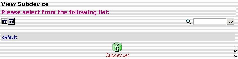
How to View Subdevices
To view subdevices, follow these steps:
Step 1 ![]() From the Subdevices Functional Overview page, select View Subdevice.
From the Subdevices Functional Overview page, select View Subdevice.
The list of subdevices appears (see Figure 2-23).
Figure 2-23 View Subdevice
Step 2 ![]() Click on the icon for the device configuration you wish to view.
Click on the icon for the device configuration you wish to view.
The Configuration for that device appears.
Note ![]() The subdevice configuration displayed is the configuration as it appears at the configuration server. It may not be the configuration running on the subdevice.
The subdevice configuration displayed is the configuration as it appears at the configuration server. It may not be the configuration running on the subdevice.
Step 3 ![]() To return to the Devices main menu, click on the Devices tab.
To return to the Devices main menu, click on the Devices tab.
How to Add Subdevices
To add the logical appearance of a subdevice to the configuration server, follow these steps:
Step 1 ![]() From the Subdevices Functional Overview page, click Add Subdevice.
From the Subdevices Functional Overview page, click Add Subdevice.
The Subdevice Information page appears (see Figure 2-24).
Figure 2-24 Subdevice Information Page

Step 2 ![]() Enter a valid value (no spaces) in the Device Name field.
Enter a valid value (no spaces) in the Device Name field.
Step 3 ![]() Accept the default value that appears or enter another valid value (no spaces) in the Config ID field.
Accept the default value that appears or enter another valid value (no spaces) in the Config ID field.
Step 4 ![]() From the Device Type drop-down list, choose the type of device to which this subdevice is associated.
From the Device Type drop-down list, choose the type of device to which this subdevice is associated.
Device type is the name of the network module as defined in the Cisco product catalog (price list).
Step 5 ![]() Choose a template file.
Choose a template file.
To use a template on your Cisco CNS Configuration Engine 1.4:
a. ![]() Choose Select file.
Choose Select file.
b. ![]() Use the drop-down list to choose a template.
Use the drop-down list to choose a template.
OR
To use an external template:
a. ![]() Choose Enter URL.
Choose Enter URL.
b. ![]() Enter the full URL for the server, directory, and filename where the template is stored. Currently, only http is supported.
Enter the full URL for the server, directory, and filename where the template is stored. Currently, only http is supported.
c. ![]() To test access to the external template, click Test URL.
To test access to the external template, click Test URL.
If the server is unavailable or the external template cannot be accessed, an error appears. You can still save this logical subdevice, but the template is not available until you have access to the external template.
Step 6 ![]() Choose a group.
Choose a group.
Step 7 ![]() To clear your entries, click Reset.
To clear your entries, click Reset.
Step 8 ![]() To add this device, click Add.
To add this device, click Add.
Step 9 ![]() To return to the Devices main menu, click on the Devices tab.
To return to the Devices main menu, click on the Devices tab.
How to Edit Subdevices
To edit information associated with a particular subdevice, follow these steps:
Step 1 ![]() From the Subdevices Functional Overview page, click Edit Subdevice.
From the Subdevices Functional Overview page, click Edit Subdevice.
Step 2 ![]() From the Edit Subdevice page, click on the icon for the subdevice you wish to edit.
From the Edit Subdevice page, click on the icon for the subdevice you wish to edit.
The subdevice configuration appears with a menu of edit functions in the left pane.
Step 3 ![]() From the left pane, choose the edit function you want to use.
From the left pane, choose the edit function you want to use.
Step 4 ![]() To go back to the Device List page, in the left pane, click << Up.
To go back to the Device List page, in the left pane, click << Up.
Step 5 ![]() To return to the Devices main menu, click on the Devices tab.
To return to the Devices main menu, click on the Devices tab.
How to Edit Subdevice Information
To edit subdevice information, follow these steps:
Step 1 ![]() From the Edit Subdevice page, click Edit Information.
From the Edit Subdevice page, click Edit Information.
The subdevice information editor dialog box appears (see Figure 2-25).
Figure 2-25 Device Information Editor

Step 2 ![]() To modify the device name, enter a valid value (no spaces) in the Device Name field.
To modify the device name, enter a valid value (no spaces) in the Device Name field.
Step 3 ![]() To modify the ConfigID, enter a valid value (no spaces) in the Config ID field.
To modify the ConfigID, enter a valid value (no spaces) in the Config ID field.
Step 4 ![]() To modify the device type, choose the appropriate device.
To modify the device type, choose the appropriate device.
Step 5 ![]() To modify the template filename, choose a new template filename.
To modify the template filename, choose a new template filename.
Step 6 ![]() Modify the template file as required.
Modify the template file as required.
Step 7 ![]() Use the Arrow buttons to modify the status of subdevices attached to this device.
Use the Arrow buttons to modify the status of subdevices attached to this device.
Step 8 ![]() To clear your entries, click Reset.
To clear your entries, click Reset.
Step 9 ![]() To update device information, click Modify.
To update device information, click Modify.
Step 10 ![]() To return to the Devices main menu, click on the Devices tab.
To return to the Devices main menu, click on the Devices tab.
How to Edit Subdevice Template
To edit a device template, follow these steps:
Step 1 ![]() From the Edit Subdevice page, click Edit Template.
From the Edit Subdevice page, click Edit Template.
The template editor appears.
Step 2 ![]() In the Attributes field, click the drop-down arrow.
In the Attributes field, click the drop-down arrow.
Step 3 ![]() Choose the attribute you wish to add to the template, then click Add.
Choose the attribute you wish to add to the template, then click Add.
Step 4 ![]() Repeat Steps 2 and 3 for all attributes you wish to add to the template file.
Repeat Steps 2 and 3 for all attributes you wish to add to the template file.
Step 5 ![]() Delete all unusable strings from the template file.
Delete all unusable strings from the template file.
Step 6 ![]() Edit strings as necessary.
Edit strings as necessary.
The default multi-line begin and end tags are ^[ and ^] respectively. The delimiter for these tags are: ~ ! @ ^ & * - = |. Do not use # or %.
A multi-line test banner might be:
banner exec ^[*
This is a Test Banner
1. Hi
2. Hello
3. Test is 1234567890*
^]
Step 7 ![]() To save your edits, click Save.
To save your edits, click Save.
Step 8 ![]() To save this version as a new template, click Save as.
To save this version as a new template, click Save as.
Step 9 ![]() To return to the Devices main menu, click on the Devices tab.
To return to the Devices main menu, click on the Devices tab.
How to Edit Subdevice Parameters
To edit subdevice parameters, follow these steps:
Step 1 ![]() From the Edit Subdevice page, click Edit Parameter.
From the Edit Subdevice page, click Edit Parameter.
The parameters editor appears.
Step 2 ![]() Modify parameters values as required.
Modify parameters values as required.
Step 3 ![]() To save your edits, click Save Parameters.
To save your edits, click Save Parameters.
Step 4 ![]() To return to the Devices main menu, click on the Devices tab.
To return to the Devices main menu, click on the Devices tab.
How to Edit Contact Information
To edit contact information related to the physical location of a device, follow these steps:
Step 1 ![]() From the Edit Device page, click Edit ContactInfo.
From the Edit Device page, click Edit ContactInfo.
The contact information appears.
Step 2 ![]() Edit all active fields as required.
Edit all active fields as required.
Step 3 ![]() To clear your entries, click Reset.
To clear your entries, click Reset.
Step 4 ![]() To save your edits, click Update.
To save your edits, click Update.
Step 5 ![]() To return the to the Devices main menu, click on the Devices tab.
To return the to the Devices main menu, click on the Devices tab.
How to Delete Subdevices
To delete the logical appearance of a subdevice from the configuration server, follow these steps:
Step 1 ![]() From the Subdevices Functional Overview page (see Figure 2-22), click Delete Device.
From the Subdevices Functional Overview page (see Figure 2-22), click Delete Device.
The Delete Subdevice page appears (see Figure 2-26).
Figure 2-26 Delete Subdevice

Step 2 ![]() To delete all subdevices in a group, check the group.
To delete all subdevices in a group, check the group.
Step 3 ![]() To delete certain subdevices in a group, click View.
To delete certain subdevices in a group, click View.
Step 4 ![]() From the list, check the subdevices you wish to delete.
From the list, check the subdevices you wish to delete.
Step 5 ![]() To proceed, click Next.
To proceed, click Next.
A status page appears indicating that the subdevice has been selected for deletion (see Figure 2-27).
Figure 2-27 Delete Subdevice

Step 6 ![]() To delete this subdevice, click Delete.
To delete this subdevice, click Delete.
Step 7 ![]() To return to the Devices main menu, click on the Devices tab.
To return to the Devices main menu, click on the Devices tab.
How to Query Device Inventory
You can use the Query Device Inventory feature to get a reports from devices about:
•![]() Running image information
Running image information
•![]() Hardware information
Hardware information
•![]() File system list
File system list
To query device inventory follow these steps:
Step 1 ![]() From the Devices Functional Overview page, click Query Device Inventory.
From the Devices Functional Overview page, click Query Device Inventory.
The Query Device Inventopry screen appears (see Figure 2-28).
Figure 2-28 Query Device Inventory

Step 2 ![]() Check the device(s) for which you want to get an inventory report(s), then click Submit.
Check the device(s) for which you want to get an inventory report(s), then click Submit.
Device inventory report(s) appear (see Figure 2-29)
Figure 2-29 Device Inventory Report

Step 3 ![]() To return to the Devices main menu, click on the Devices tab.
To return to the Devices main menu, click on the Devices tab.
How to Manage User Accounts
To begin managing user accounts, follow these steps:
Step 1 ![]() Login to the system (see "How to Login and Out of the System" section).
Login to the system (see "How to Login and Out of the System" section).
Step 2 ![]() From the Home page, click on the Users tab.
From the Home page, click on the Users tab.
A functional overview of the user administration options appears (see Figure 2-30).
Figure 2-30 User Administration Overview

How to Add a User Account
To add a user account, follow these steps:
Step 1 ![]() From the User Administration page, click Add User.
From the User Administration page, click Add User.
The User Information dialog box appears (see Figure 2-31).
Figure 2-31 User Information

Step 2 ![]() Enter a valid value (no spaces) in the UserID field.
Enter a valid value (no spaces) in the UserID field.
Table 2-9 lists valid values for these fields.
Step 3 ![]() Enter a password in the Password field.
Enter a password in the Password field.
Step 4 ![]() Confirm the password by entering it again in the Confirm Password field.
Confirm the password by entering it again in the Confirm Password field.
Step 5 ![]() Enter the user's last name in the Last Name field.
Enter the user's last name in the Last Name field.
Step 6 ![]() Enter the user's first name in the First Name field.
Enter the user's first name in the First Name field.
Step 7 ![]() In the Group pane, click the radio button that classifies the privilege level (Administrator, Operator) of this user.
In the Group pane, click the radio button that classifies the privilege level (Administrator, Operator) of this user.
Step 8 ![]() To clear your entries, click Reset.
To clear your entries, click Reset.
Step 9 ![]() To save your entries, click Save.
To save your entries, click Save.
Step 10 ![]() To return to the Users main menu, click on the Users tab.
To return to the Users main menu, click on the Users tab.
How to Edit a User Account
To edit a user account, follow these steps:
Step 1 ![]() From the User Administration page, click Edit User.
From the User Administration page, click Edit User.
A list of users appears (see Figure 2-32).
Figure 2-32 User List

Step 2 ![]() From the User List, click on the icon for the user account you wish to edit.
From the User List, click on the icon for the user account you wish to edit.
Note ![]() Administrator-level users are shown with a key icon associated with the figure icon.
Administrator-level users are shown with a key icon associated with the figure icon.
The User Information page appears (see Figure 2-33).
Figure 2-33 User Information

Step 3 ![]() To modify the user ID, enter a valid value (no spaces) in the UserID field.
To modify the user ID, enter a valid value (no spaces) in the UserID field.
Table 2-10 list valid values for these fields.
Step 4 ![]() To modify the user's last name, edit the Last Name field.
To modify the user's last name, edit the Last Name field.
Step 5 ![]() To modify the user's first name, edit the First Name field.
To modify the user's first name, edit the First Name field.
Step 6 ![]() To modify the user group status, click the appropriate radio button in the Group pane.
To modify the user group status, click the appropriate radio button in the Group pane.
Step 7 ![]() To clear your entries, click Reset.
To clear your entries, click Reset.
Step 8 ![]() To save your entries, click Save.
To save your entries, click Save.
User information update status appears (see Figure 2-34).
Step 9 ![]() To return to the Users main menu, click on the Users tab.
To return to the Users main menu, click on the Users tab.
Figure 2-34 User Information Update Status

How to Delete a User Account
To delete a user account, follow these steps:
Step 1 ![]() From the User Administration page, click Delete User.
From the User Administration page, click Delete User.
Step 2 ![]() From the user list (see Figure 2-32), click on the icon for the user account you wish to delete.
From the user list (see Figure 2-32), click on the icon for the user account you wish to delete.
Step 3 ![]() To return to the Users main menu, click on the Users tab.
To return to the Users main menu, click on the Users tab.
How to Change or Reset a User Password
To change or reset a user password, follow these steps:
Step 1 ![]() From the User Administration page, click Change Password.
From the User Administration page, click Change Password.
The Change Password dialog box (see Figure 2-35) appears.
Figure 2-35 Change Password

Step 2 ![]() Enter the UserID for the user account password you want to change or reset.
Enter the UserID for the user account password you want to change or reset.
Table 2-11 lists valid values for these fields.
Step 3 ![]() Enter the new password in the New password field.
Enter the new password in the New password field.
Step 4 ![]() Enter the new password again in the Confirm password field.
Enter the new password again in the Confirm password field.
Step 5 ![]() To clear your entries, click Reset.
To clear your entries, click Reset.
Step 6 ![]() To save the new password, click Edit.
To save the new password, click Edit.
Step 7 ![]() To return to the Users main menu, click on the Users tab.
To return to the Users main menu, click on the Users tab.
How to Change Account Privilege Level
To change the privilege level of a user account, follow these steps:
Step 1 ![]() From the User Administration page, click Edit User.
From the User Administration page, click Edit User.
Step 2 ![]() Choose the user in question from the user list (see Figure 2-32).
Choose the user in question from the user list (see Figure 2-32).
The User Information page appears (see Figure 2-36).
Figure 2-36 User Information

Step 3 ![]() In the Group pane, click the radio button that classifies the privilege level (Administrator, Operator) of this user.
In the Group pane, click the radio button that classifies the privilege level (Administrator, Operator) of this user.
Step 4 ![]() To clear your entries, click Reset.
To clear your entries, click Reset.
Step 5 ![]() To save your entries, click Save.
To save your entries, click Save.
Step 6 ![]() To return to the Users main menu, click on the Users tab.
To return to the Users main menu, click on the Users tab.
Device Configuration Order Entry
To conduct device configuration order entry tasks, from the Home page, click the Order Entry tab. The Order Entry page appears (see Figure 2-37).
Figure 2-37 Device Configuration Order Entry

How to Enter an Order for a New Device Configuration
To enter a new device configuration order, follow these steps:
Step 1 ![]() From the Order Entry Functional Overview page, click New Order.
From the Order Entry Functional Overview page, click New Order.
The order information dialog box appears (see Figure 2-38).
Figure 2-38 New Device Configuration Order

Step 2 ![]() Enter a valid value (no spaces) in the Device Name field.
Enter a valid value (no spaces) in the Device Name field.
Table 2-12 list valid values for these fields.
Step 3 ![]() Enter a valid value (no spaces) in the Event ID field.
Enter a valid value (no spaces) in the Event ID field.
Step 4 ![]() Enter a valid value (no spaces) in the Config ID field.
Enter a valid value (no spaces) in the Config ID field.
Step 5 ![]() Choose a template file.
Choose a template file.
To use a template on your Cisco CNS Configuration Engine 1.4:
a. ![]() Choose Select file.
Choose Select file.
b. ![]() Use the drop-down menu to choose a template.
Use the drop-down menu to choose a template.
OR
To use an external template:
a. ![]() Choose Enter URL.
Choose Enter URL.
b. ![]() Enter the full URL for the server, directory, and filename where the template is stored. Currently, only http is supported.
Enter the full URL for the server, directory, and filename where the template is stored. Currently, only http is supported.
c. ![]() To test access to the external template, click Test URL.
To test access to the external template, click Test URL.
If the server is unavailable or the external template cannot be accessed, an error appears. You can still save this logical device, but the template is not available until you have access to the external template.
Step 6 ![]() Choose a group.
Choose a group.
Tip ![]() Use the Group Manager under DAT (see "How to Add a Group" section) to set up groups before you add a device.
Use the Group Manager under DAT (see "How to Add a Group" section) to set up groups before you add a device.
Step 7 ![]() To clear your entries, click Reset.
To clear your entries, click Reset.
Step 8 ![]() To add this device, click Add.
To add this device, click Add.
Confirmation page appears.
Step 9 ![]() Click Update Contact Information.
Click Update Contact Information.
Contact information page appears.
Step 10 ![]() To update contact information, fill in all applicable field.
To update contact information, fill in all applicable field.
Step 11 ![]() To clear your entries, click Reset.
To clear your entries, click Reset.
Step 12 ![]() To continue, click Add.
To continue, click Add.
Confirmation page appears.
Step 13 ![]() Click Edit Parameters.
Click Edit Parameters.
If there are parameters in the configuration template, they appear. Otherwise, skip.
Step 14 ![]() Enter values for parameters.
Enter values for parameters.
Step 15 ![]() Click Apply Template.
Click Apply Template.
A confirmation page appears.
Step 16 ![]() To save, but not apply, click Save.
To save, but not apply, click Save.
Step 17 ![]() To save and apply, Save and Apply.
To save and apply, Save and Apply.
Step 18 ![]() To clear your entry, click Reset.
To clear your entry, click Reset.
Step 19 ![]() To return to the Order Entry main menu, click on the Order Entry tab.
To return to the Order Entry main menu, click on the Order Entry tab.
Editing an Existing Configuration Order
To edit an existing configuration order, follow these steps:
Step 1 ![]() From the Order Entry Functional Overview page, click Edit Order.
From the Order Entry Functional Overview page, click Edit Order.
The Edit Order page appears (see Figure 2-39).
Step 2 ![]() Click on the icon for the device configuration order you wish to edit.
Click on the icon for the device configuration order you wish to edit.
The device configuration order editor appears with a menu of edit functions in the left pane.
Figure 2-39 Edit Order Device List

How to Edit Existing Order Information
To edit existing order information, follow these steps:
Step 1 ![]() From the Order Editor page, click Edit Information.
From the Order Editor page, click Edit Information.
The order information dialog box appears.
Step 2 ![]() To modify the device name, enter a valid value (no spaces) in the Device Name field.
To modify the device name, enter a valid value (no spaces) in the Device Name field.
Step 3 ![]() To modify the EventID, enter a valid value (no spaces) in the Event ID field.
To modify the EventID, enter a valid value (no spaces) in the Event ID field.
Step 4 ![]() To modify the ConfigID, enter a valid value (no spaces) in the Config ID field.
To modify the ConfigID, enter a valid value (no spaces) in the Config ID field.
Step 5 ![]() To modify the template filename, choose a new template filename.
To modify the template filename, choose a new template filename.
Step 6 ![]() Modify the template file as required.
Modify the template file as required.
Step 7 ![]() To clear your entries, click Reset.
To clear your entries, click Reset.
Step 8 ![]() To save your edits, click Modify.
To save your edits, click Modify.
Step 9 ![]() To return to the Order Entry main menu, click on the Order Entry tab.
To return to the Order Entry main menu, click on the Order Entry tab.
How to Edit Parameters
To edit parameter for an order, follow these steps:
Step 1 ![]() From the Order Editor page, click Edit Parameters.
From the Order Editor page, click Edit Parameters.
The parameter editor appears (see Figure 2-40).
Figure 2-40 Parameter Editor

Step 2 ![]() Edit the value(s) of all applicable fields.
Edit the value(s) of all applicable fields.
Table 2-13 list valid values for these fields.
|
|
|
|
|---|---|---|
Parameter Name |
Name of parameter set for the device |
a-z |
Step 3 ![]() To save, but not apply, click Save.
To save, but not apply, click Save.
Step 4 ![]() To save and apply, Save and Apply.
To save and apply, Save and Apply.
Step 5 ![]() To clear your entry, click Reset.
To clear your entry, click Reset.
A parameter save and apply status page appears.
Figure 2-41 Parameter Save Status

Step 6 ![]() Use the radio buttons to choose a Config Action, then click Update Device via Event.
Use the radio buttons to choose a Config Action, then click Update Device via Event.
Step 7 ![]() To return to the Order Entry main menu, click on the Order Entry tab.
To return to the Order Entry main menu, click on the Order Entry tab.
How to Edit Contact Information
To edit contact information for an existing order, follow these steps:
Step 1 ![]() From the Order Editor page, click Edit ContactInfo.
From the Order Editor page, click Edit ContactInfo.
The contact information appears (see Figure 2-42).
Figure 2-42 Contact Information (Partial View)

Step 2 ![]() Edit all active fields as required.
Edit all active fields as required.
Table 2-14 list valid values for these fields.
|
|
|
|
|---|---|---|
All Fields |
Contact information fields |
a-z |
Step 3 ![]() To clear your entries, click Reset.
To clear your entries, click Reset.
Step 4 ![]() To save your edits, click Update.
To save your edits, click Update.
Step 5 ![]() To return the to the Order Entry main menu, click on the Order Entry tab.
To return the to the Order Entry main menu, click on the Order Entry tab.
Managing Subdevice Configuration Orders
To enter new subdevice configuration orders or edit existing ones, from the Order Entry page, click Subdevice Order. The subdevice order entry page appears (see Figure 2-43).
Figure 2-43 New Subdevice Order Entry

How to Enter an Order for a New Subdevice Configuration
To enter an order for a new subdevice configuration, follow these steps:
Step 1 ![]() From the Subdevice Order page, click New Subdevice Order.
From the Subdevice Order page, click New Subdevice Order.
The subdevice information page appears (see Figure 2-44).
Figure 2-44 New Subdevice Order Entry Information

Step 2 ![]() Enter a valid value (no spaces) in the Device Name field.
Enter a valid value (no spaces) in the Device Name field.
Table 2-15 list valid values for these fields.
Step 3 ![]() Accept the default value that appears or enter another valid value (no spaces) in the Config ID field.
Accept the default value that appears or enter another valid value (no spaces) in the Config ID field.
Step 4 ![]() From the Device Type drop-down menu, choose the type of device to which this subdevice is associated.
From the Device Type drop-down menu, choose the type of device to which this subdevice is associated.
Step 5 ![]() Choose a template file.
Choose a template file.
To use a template on your Cisco CNS Configuration Engine 1.4:
a. ![]() Choose Select file.
Choose Select file.
b. ![]() Use the drop-down list to choose a template.
Use the drop-down list to choose a template.
OR
To use an external template:
a. ![]() Choose Enter URL.
Choose Enter URL.
b. ![]() Enter the full URL for the server, directory, and filename where the template is stored. Currently, only http is supported.
Enter the full URL for the server, directory, and filename where the template is stored. Currently, only http is supported.
c. ![]() To test access to the external template, click Test URL.
To test access to the external template, click Test URL.
If the server is unavailable or the external template cannot be accessed, an error appears. You can still save this logical subdevice, but the template is not available until you have access to the external template.
Step 6 ![]() Choose a group.
Choose a group.
Step 7 ![]() To clear your entries, click Reset.
To clear your entries, click Reset.
Step 8 ![]() To add this device, click Add.
To add this device, click Add.
Step 9 ![]() To return to the Order Entry main menu, click on the Order Entry tab.
To return to the Order Entry main menu, click on the Order Entry tab.
How to Edit an Existing Order for a Subdevice Configuration
To edit an existing order for a new subdevice configuration, follow these steps:
Step 1 ![]() From the Subdevice Order page, click Edit Subdevice Order.
From the Subdevice Order page, click Edit Subdevice Order.
Step 2 ![]() From the Subdevice List page, click on the icon for the subdevice you wish to edit.
From the Subdevice List page, click on the icon for the subdevice you wish to edit.
The subdevice configuration appears with a menu of edit functions in the left pane (see Figure 2-45).
Figure 2-45 ESubdevice Order

How to Edit Subdevice Information
To edit subdevice information, follow these steps:
Step 1 ![]() From the Edit Subdevice page, click Edit Information.
From the Edit Subdevice page, click Edit Information.
The subdevice information editor dialog box appears (see Figure 2-46).
Figure 2-46 Subdevice Information Editor

Step 2 ![]() To modify the device name, enter a valid value (no spaces) in the Device Name field.
To modify the device name, enter a valid value (no spaces) in the Device Name field.
Table 2-16 list valid values for these fields.
Step 3 ![]() To modify the ConfigID, enter a valid value (no spaces) in the Config ID field.
To modify the ConfigID, enter a valid value (no spaces) in the Config ID field.
Step 4 ![]() To modify the device type, choose the appropriate device.
To modify the device type, choose the appropriate device.
Step 5 ![]() To modify the template filename, choose a new template filename.
To modify the template filename, choose a new template filename.
Step 6 ![]() Modify the template file as required.
Modify the template file as required.
Step 7 ![]() Use the Arrow buttons to modify the status of subdevices attached to this device.
Use the Arrow buttons to modify the status of subdevices attached to this device.
Step 8 ![]() To clear your entries, click Reset.
To clear your entries, click Reset.
Step 9 ![]() To update device information, click Modify.
To update device information, click Modify.
Step 10 ![]() To return to the Order Entry main menu, click on the Order Entry tab.
To return to the Order Entry main menu, click on the Order Entry tab.
How to Edit Subdevice Parameters
To edit subdevice parameters, follow these steps:
Step 1 ![]() From the Edit Subdevice page, click Edit Parameter.
From the Edit Subdevice page, click Edit Parameter.
The parameters editor appears.
Step 2 ![]() Modify parameters values as required.
Modify parameters values as required.
Step 3 ![]() To save your edits, click Save Parameters.
To save your edits, click Save Parameters.
Step 4 ![]() To return to the Order Entry main menu, click on the Order Entry tab.
To return to the Order Entry main menu, click on the Order Entry tab.
How to Edit Contact Information
To edit contact information related to the physical location of a device, follow these steps:
Step 1 ![]() From the Edit Device page, click Edit ContactInfo.
From the Edit Device page, click Edit ContactInfo.
The contact information appears.
Step 2 ![]() Edit all active fields as required.
Edit all active fields as required.
Step 3 ![]() To clear your entries, click Reset.
To clear your entries, click Reset.
Step 4 ![]() To save your edits, click Update.
To save your edits, click Update.
Step 5 ![]() To return the to the Order Entry main menu, click on the Order Entry tab.
To return the to the Order Entry main menu, click on the Order Entry tab.
Management Tools
To use the management tools, from the Home page, click on the Tools tab.
The Tools page appears (see Figure 2-47).
Figure 2-47 Management Tools

How to Use DAT
To connect to the user interface for the Directory Administration Tool (DAT), follow these steps:
Step 1 ![]() From the Tools main menu, click DAT.
From the Tools main menu, click DAT.
The login window appears (see Figure 2-48).
Figure 2-48 Directory Administration Tool Login Window

Step 2 ![]() Enter your User ID.
Enter your User ID.
This is the LDAP proxy user name for the Cisco CNS Configuration Engine 1.4 administrative account that you entered during Setup.
Step 3 ![]() Enter your LDAP proxy password.
Enter your LDAP proxy password.
Step 4 ![]() Click LOGIN.
Click LOGIN.
The Directory Administration Tool Overview page appears (see Figure 2-49).
Figure 2-49 DAT Home Page

Step 5 ![]() From here, go to "Directory Administration Tool" and follow the procedures for the tasks you want to run.
From here, go to "Directory Administration Tool" and follow the procedures for the tasks you want to run.
Managing Data
From the Tools page, click Data Manager. The Data Manager page appears (see Figure 2-50).
Figure 2-50 Data Manager

How to Schedule Data Backup
To schedule a data backup, follow these steps:
Step 1 ![]() From the Data Manager Overview page, click ScheduleBackup.
From the Data Manager Overview page, click ScheduleBackup.
The backup information dialog box appears (see Figure 2-51).
Figure 2-51 Backup Schedule Parameters

Step 2 ![]() To specify where you want the backup data to be stored, enter the FTP server name in the FTP Server Name field.
To specify where you want the backup data to be stored, enter the FTP server name in the FTP Server Name field.
Table 2-17 list valid values for these fields.
Step 3 ![]() To specify the username to login to the FTP server, enter a valid username in the Username field.
To specify the username to login to the FTP server, enter a valid username in the Username field.
Step 4 ![]() To specify the password to use to login to the FTP server, enter a valid value in the Password field.
To specify the password to use to login to the FTP server, enter a valid value in the Password field.
Step 5 ![]() To specify the subdirectory where the data file is put, enter the absolute path in the Directory field.
To specify the subdirectory where the data file is put, enter the absolute path in the Directory field.
Step 6 ![]() Choose whether to Enable Log File Management.
Choose whether to Enable Log File Management.
Step 7 ![]() To specify the backup schedule, complete the fields in the Backup Schedule pane.
To specify the backup schedule, complete the fields in the Backup Schedule pane.
Note ![]() The time base for the CNS 2100 Series system should be set to Coordinated Universal Time (UTC).
The time base for the CNS 2100 Series system should be set to Coordinated Universal Time (UTC).
Step 8 ![]() To cancel the backup operation, click Cancel.
To cancel the backup operation, click Cancel.
Step 9 ![]() To start the backup operation, click Backup.
To start the backup operation, click Backup.
Step 10 ![]() To return to the Tools main menu, click on the Tools tab.
To return to the Tools main menu, click on the Tools tab.
For more information about backup and restore, refer to the Cisco CNS Configuration Engine 1.4 Installation & Setup Guide For Linux.
How to Update Product List
The product list is a mapping between product name of the network modules as specified in the pricing list and the numeric identification number stored in EPROM. As new products are added, this list grows and hence the need for the Cisco CNS Configuration Engine 1.4 to update this list whenever new products are added. This list can be downloaded from the Cisco web site at: http://www.cisco.com.
To update the product list, follow these steps:
Step 1 ![]() From the Data Manager page, click Update Product List.
From the Data Manager page, click Update Product List.
The Update Product List dialog box appears (see Figure 2-52).
Figure 2-52 Update Product List

Step 2 ![]() Select the appropriate download option.
Select the appropriate download option.
Table 2-18 list valid values for these fields.
Step 3 ![]() Enter the target URL.
Enter the target URL.
Step 4 ![]() Enter your username and password.
Enter your username and password.
Step 5 ![]() To download the product list, click Download.
To download the product list, click Download.
Step 6 ![]() To return to the Tools main menu, click on the Tools tab.
To return to the Tools main menu, click on the Tools tab.
How to Manage Disk Space
To setup disk space e-mail notification of disk space usage, follow these steps:
Step 1 ![]() From the Group Manager page, click Manage Disk Space.
From the Group Manager page, click Manage Disk Space.
The Setup Disk Space Notification dialog box appears (see Figure 2-53).
Figure 2-53 Disk Space Notification

Step 2 ![]() Set the notification percentage to the value that triggers an e-mail notification.
Set the notification percentage to the value that triggers an e-mail notification.
Table 2-19 list valid values for these fields.
Step 3 ![]() Set the appropriate e-mail address for notification e-mail.
Set the appropriate e-mail address for notification e-mail.
Step 4 ![]() To save these entries, click Save.
To save these entries, click Save.
Step 5 ![]() To return to the Tools main menu, click on the Tools tab.
To return to the Tools main menu, click on the Tools tab.
How to Manage Directory Content
With the directory manager you can:
•![]() Edit the schema
Edit the schema
•![]() Import a schema from an XML file
Import a schema from an XML file
To use the directory manager tool, click Directory Mgr.
The Directory Manager page appears (see Figure 2-54).
Figure 2-54 Directory Manager

How to Edit the Schema
To edit the schema, follow these steps:
Step 1 ![]() From the Directory Manager page, click Edit Schema.
From the Directory Manager page, click Edit Schema.
The schema editor appears (see Figure 2-55).
Figure 2-55 Schema Editor

Step 2 ![]() From drop-down list, select name of class to which attribute belongs.
From drop-down list, select name of class to which attribute belongs.
Table 2-20 list valid values for these fields.
Step 3 ![]() Enter the name of the new attribute
Enter the name of the new attribute
Step 4 ![]() Accept or modify the Unique ID for this attribute.
Accept or modify the Unique ID for this attribute.
Step 5 ![]() To clear your entries, click Reset.
To clear your entries, click Reset.
Step 6 ![]() To add this attribute to the schema, click Add Entry.
To add this attribute to the schema, click Add Entry.
Step 7 ![]() To return to the Tools main menu, click on the Tools tab.
To return to the Tools main menu, click on the Tools tab.
How to Import Schema
You can import a schema accessible from your computer. However, the file must be in XML format and conform to the definitions specified in the document type definition (DTD) file shown here:
<!-- DTD for DAML -->
<!-- Last updated: 2000-10-03 -->
<!ELEMENT daml (schema)>
<!-- SCHEMA -->
<!ELEMENT schema (class+,attribute-type+,link*)>
<!-- element types common to class and attribute-type -->
<!ELEMENT class (auxclass*,attribute+)>
<!ATTLIST class
name (#PCDATA) #REQUIRED
id ID #IMPLIED
superior IDREF #IMPLIED
type (structural|abstract|auxiliary) #REQUIRED
description? #IMPLIED
>
<!ELEMENT auxclass EMPTY>
<!ATTLIST auxclass
ref IDREF #REQUIRED
>
<!ELEMENT attribute EMPTY>
<!ATTLIST attribute
ref IDREF #REQUIRED
required (true|false) #REQUIRED
>
<!ELEMENT attribute-type EMPTY>
<!ATTLIST attribute-type
name (#PCDATA) #REQUIRED
id ID #REQUIRED
single-value (true|false) "false"
syntax (string|integer|boolean|binary|key) "string"
>
<!ELEMENT link EMPTY>
<!ATTLIST link
fromclass IDREF #REQUIRED
fromattr IDREF #REQUIRED
toclass IDREF #REQUIRED
toattr IDREF #REQUIRED
>
For example, a valid schema would look like:
<?xml version="1.0" encoding="UTF-8"?>
<!DOCTYPE dsml SYSTEM "dsml.dtd">
<dsml complete="true">
<directory-schema>
   <attribute-type id="IOSe1ipaddress" single-value="true" obsolete="false"
user-modification="true">
<name>IOSe1ipaddress</name>
<object-identifier>1.2.840.113548.3.1.2.20</object-identifier>
<syntax>string</syntax>
</attribute-type>
<class id="IOSConfigClass" superior="top" type="structural" obsolete="false">
<name>IOSConfigClass</name>
<object-identifier>1.2.840.113548.3.2.2.1</object-identifier>
<attribute ref="1.2.840.113548.3.1.2.20" required="false"/>
</class>
</directory-schema>
</dsml>
To import a schema from an XML file accessible from your computer, follow these steps:
Step 1 ![]() From the Directory Manager page, click Import Schema.
From the Directory Manager page, click Import Schema.
The import schema dialog box appears (see Figure 2-56).
Figure 2-56 Import Schema

Step 2 ![]() Enter the filename of the schema you want to import in the Schema Filename field.
Enter the filename of the schema you want to import in the Schema Filename field.
Table 2-21 list valid values for these fields.
|
|
|
|
|---|---|---|
Schema Filename |
Name of schema file to import. |
a-z |
Use the browse function to locate the file, if needed.
Step 3 ![]() To clear your entries, click Reset.
To clear your entries, click Reset.
Step 4 ![]() To import the file, click Import.
To import the file, click Import.
Step 5 ![]() To return to the Tools main menu, click on the Tools tab.
To return to the Tools main menu, click on the Tools tab.
Templates and Template Management
When creating a template, it is possible to specify variables that will be contextually substituted. Many of these variables are available in the drop-down menu in the Template Editor (see Figure 2-60). It is also possible to create these files offline without the Template Editor and still use these variables.
The basic format of a template file is simply the text of the configuration to be downloaded to your device (see "Sample Template" section). However, you can put variable substitutions of the following form (for example, the variable name could be iosipaddress):
Internal directory mode:
${LDAP://this:attrName=iosipaddress}
External directory mode:
${LDAP://10.1.2.3/cn=Device1,ou=CNSDevices,o=cisco,c=us:attrName=iosipaddress}
It is possible to create segments of templates that can be included in other templates. For example, you might have an Ethernet configuration that would be used by multiple devices. In each device template, you could have:
#include /opt/CSCOcnsie/Templates/ethernet_setup.cfgtpl
Now, you could centralize all the administration for Ethernet configuration in one file.

Sample Template
The following sample is the configuration template for the DemoRouter (DemoRouter.cfgtpl), which is pre-loaded on your system:
!
version 12.0
service timestamps debug uptime
service timestamps log uptime
no service password-encryption
service udp-small-servers
service tcp-small-servers
!
hostname DemoRouter
!
boot system flash c7200-is-mz
enable secret 5 $1$cMdI$.e37TH540MWB2GW5gMOn3/
enable password cisco
!
ip subnet-zero
!
interface FastEthernet0/0
no ip address
no ip directed-broadcast
no ip route-cache
no ip mroute-cache
shutdown
half-duplex
!
interface Ethernet1/0
ip address 10.10.1.1 255.255.255.240
no ip directed-broadcast
no ip route-cache
no ip mroute-cache
!
interface Ethernet1/1
no ip address
no ip directed-broadcast
no ip route-cache
no ip mroute-cache
shutdown
!
interface Ethernet1/2
no ip address
no ip directed-broadcast
no ip route-cache
no ip mroute-cache
shutdown
!
interface Ethernet1/3
no ip address
no ip directed-broadcast
no ip route-cache
no ip mroute-cache
shutdown
!
ip classless
ip route 0.0.0.0 0.0.0.0 10.10.1.1
ip http server
!
dialer-list 1 protocol ip permit
dialer-list 1 protocol ipx permit
!
line con 0
transport input none
line aux 0
line vty 0 4
password cisco
login
!
end
Configuration Control Templates
To restart a device with a new image, you need Configuration Control templates that contain the required CLI commands for image activation on particular devices.
For example, if you want to restart a Cisco 3600 Series router with an image named 3600.image, from the device console, you would issue the following CLI commands:
no boot system
boot system flash:3600.image
The content of the Configuration Control template for image activation should contain the CLI commands that you would normally enter from the device console to activate a new image on the device.
Templates for Modular Routers
The template mechanism for the devices has been enhanced to support modular routers. A modular router chassis includes slots in which you can install modules. You can install any module into any available slot in the chassis. Some modules like 2 Ethernet 2 WAN card slot module can in turn have sub slots to install interface cards or line cards. Device management has been extended to support subdevices representing line cards.
Additional attributes representing line card number, line card type, and subdevices have been added to the existing device object structure in the directory server in order to have the same structure to represent the main device or the subdevice.
Currently, card type is a string that maps to the product code of the network module. Since the EPROM data in the card stores part numbers only, not product codes, the part numbers are mapped to product codes. The user uses part numbers and the configuration server maps part number to product codes.
In the context of main device, the line card number and line card type fields make no sense and hence are set to NULL value. The subdevices field in the sub device (representing the line card) is set to NULL value.
New interface variable support has been added. These variables are included in the templates, which are parameterize with the interface numbers in the template. These are not attributes. They are special format variables that are replaced by the configuration server based on the interface information, which comes from the device. These variables only specify the relative position of the interface on the module and are replaced by the actual slot number, shelf-ID or port number. The interface variables are wrapped in percent sign (%) characters and specify the type, if any, and the relative position. The configuration server replaces these variables with the interface numbers. The interface type still has to be specified in the CLI using the following syntax:
Interface Variable = %[InterfaceType] RelativePosition%
For example:
%FastEthernet 0% for interface FastEthernet
%Serial 0% interface Serial
%T1 0% controller T1
%E1 0% controller E1
%voice-port 0% voice-port
Example 1:
A network module with two FastEthernet ports plugged in Slot 2 would be referred in the configuration CLI as FastEthernet 2/0 and FastEthernet 2/1 and referred in the template as FastEthernet %FastEthernet 0% and FastEthernet %FastEthernet 1%:
!
interface FatsEthernet 2/0
ip address 10.10.1.1 255.255.255.0
!
interface FatsEthernet 2/1
ip address 20.20.1.1 255.255.255.0
!
Templates for these CLIs would be:
!
interface FastEthernet %FastEthernet 0%
ip address 10.10.1.1 255.255.255.0
!
interface FastEthernet %FastEthernet 1%
ip address 20.20.1.1 255.255.255.0
!
Example 2 (Voice card with two ports plugged in slot 3):
!
voice-port 3/0/0
description 4082224444
!
voice-port 3/0/0
description 4082225555
!
Templates for these CLIs would be:
!
voice-port %voice-port 0%
description 4082224444
!
voice-port %voice-port 1%
description 4082225555
!
The main device template does not include links to the subdevice templates. The subdevice templates are appended to the main device template. The line card number are a parameter in the subdevice templates.
All the CLI commands which reference a line card interface are specified in the subdevice template for that line card. This implies that any command in the global configuration mode, or otherwise, that refers to a particular line card interface is in the template for that subdevice (line card) and not in the main device template.
Only the CLI commands in the global configuration mode, and not pertaining to the any specific interface, are specified in the main device template.
The port number and channel number are not be template parameters since these are fixed for a given line card. The network administrator can configure specific channels on the interfaces by explicitly specifying the channels in the subdevice templates.
For example:
interface Serial %Serial 0%:0
Sample Templates for Modular Router
The names of the attributes for slot, slot-unit, line card type and so forth, are used for demonstration purposes.
Main Device Template
!
version 12.2
no parser cache
no service single-slot-reload-enable
service timestamps debug uptime
service timestamps log uptime
no service password-encryption
!
hostname 2600
!
logging rate-limit console 10 except errors
!
memory-size iomem 25
ip subnet-zero
!
!
!
no ip dhcp-client network-discovery
lcp max-session-starts 0
!
ip classless
no ip http server
!
call rsvp-sync
!
no mgcp timer receive-rtcp
!
mgcp profile default
!
dial-peer cor custom
!
!
!
!
line con 0
line aux 0
line vty 0 4
login
line vty 5 15
login
!
Fastethernet Template
Interface FastEthernet %FastEthernet 0%
ip address 10.0.0.1 255.0.0.0
shutdown
speed auto
Voice-port Template
voice-port %voice-port 0%
playout-delay mode adaptive
!
voice-port %voice-port 1%
!
dial-peer voice 10 pots
destination-pattern 200
port %voice-port 0%
forward-digits all
voice-port %voice-port 0%
!
dial-peer voice 20 pots
destination-pattern 100
port %voice-port 0%
!
voice-port %voice-port 1%
Modular Router Events
Modular router events are published to the event bus and are accessible to applications connected to the bus. The IOS device publishes the system hardware configuration in the cisco.cns.config.device-details event after hardware discovery. The Cisco CNS Configuration Engine 1.4 is configured to listen for this event, retrieve it and extract the hardware configuration of the device.
Following is the DTD of the cisco.cns.config.device-details event that the Cisco IOS device sends:
<!ELEMENT device-details (config-id, connect-interface?, card-info*>
<!ELEMENT config-id (#PCDATA)>
<!ELEMENT connect-interface (#PCDATA)>
<!ELEMENT card-info (card-info+)>
	<!ELEMENT card-info
(card-type,card-desc?,slot,daughter?,serial-number,part-number,hw-version?,board-revision?
,ports?,controller?,rma-number?,test-history?,eeprom-version?,eeprom-data?,interface?,cont
roller?,voice-port?)>
<!ELEMENT card-type (#PCDATA)>
<!ELEMENT card-desc (#PCDATA)>
<!ELEMENT slot (#PCDATA)>
<!ELEMENT daughter (#PCDATA)>
<!ELEMENT serial-number (#PCDATA)>
<!ELEMENT part-number (#PCDATA)>
<!ELEMENT hw-version (#PCDATA)>
<!ELEMENT board-revision (#PCDATA)>
<!ELEMENT ports (#PCDATA)>
<!ELEMENT controller (#PCDATA)>
<!ELEMENT rma-number (#PCDATA)>
<!ELEMENT test-history (#PCDATA)>
<!ELEMENT eeprom-version (#PCDATA)>
<!ELEMENT eeprom-data (#PCDATA)>
<!ELEMENT interface (#PCDATA)>
<!ELEMENT controller (#PCDATA)>
<!ELEMENT voice-port (#PCDATA)>
Dynamic Templates
There may be times when the actual contents of a template needs to be dynamically generated. To do this, you would use the #call mechanism. This executes a JavaScript program whose output becomes part of the template. The program is re-executed each time a device asks for the template.
For example, you might want to distribute the load across the various event gateway processes without permanently assigning a device to a particular event gateway. This is useful because of the limit of 500 devices per event gateway daemon instance.
Let us take the following template as an example:
version 12.0
service timestamps debug uptime
service timestamps log uptime
no service password-encryption
service udp-small-servers
service tcp-small-servers
!
hostname DemoRouter
#call /opt/CSCOcnsie/Templates/event_setup.js
Here is an example of an event_setup.js that one might use:
/*
* An instance of Event Gateway resides on every odd port from 11011 to 11031.
* This will choose a random one in this range so that devices are spread out
* evenly among the various ports. Adjust the IP address in the println
* statement to be the address of the IE2100 itself.
*/
var port = Math.floor(Math.random() * 11) * 2 + 11011;
println("cns event 10.1.6.131 " + port.toString());
The result of this combination would be a template that appears as follows:
version 12.0
service timestamps debug uptime
service timestamps log uptime
no service password-encryption
service udp-small-servers
service tcp-small-servers
!
hostname DemoRouter
cns event 10.1.6.131 11017
The last line is programmatically determined and recalculated every time the template is requested by the device. So the next time a device requests this template, the last line might be:
cns event 10.1.6.131 11023
Simple modifications to event_setup.js could even be used to distribute devices across multiple CNS 2100 Series devices (by dynamically generating the IP address). It could also be used to affect any part of the device configuration—be it DNS servers or routing tables. Anything that is printed out by the JavaScript program becomes a dynamic part of the template.
Control Structures
The configuration template can include simple control structures such as, if, else and elseif. By using these control structures, the user can include or exclude a block of CLI commands based on a parameter stored in the directory.
The syntax for these # preprocessing control structures is as follows:
Syntax Description
#if <URL> = constant
cli-command(s)
#elseif <URL> = constant
cli-command(s)
#else
cli-command(s)
#endif
Where constant is an integer, boolean or a string in single quotes and the <URL> is a URL pointing to an attribute in the Directory or Database.
Note ![]() Nested #if and #elseif is NOT supported.
Nested #if and #elseif is NOT supported.
Usage Guidelines
The configuration template can include #define entries to define short names for long URLs.
The syntax for the #define preprocessing command is as follows
#define definition-name <URL> | constant
where <URL> is a reference to an attribute in the directory.
The configuration template can contain another # preprocessing command #include, which allows the inclusion of other configuration templates or the results of an ASP page.
The syntax for the # preprocessing command is as follows:
#include <URL> | `<Filename>' | <Filename>
Whenever an #include directive is encountered, it is replaced by the content of the file.
The following configuration template sample includes either IP sub-template or ISDN sub-template based on the value of the parameter protocol in the directory or database.
Examples
!
version 12.0
service timestamps debug uptime
service timestamps log uptime
no service password-encryption
service udp-small-servers
service tcp-small-servers
!
hostname ${LDAP://this:attrName=IOShostname}
#if ${LDAP://this:attrName=IOSIPprotocol} = true then
#include ${LDAP://this:attrName=IPsubTemplate}
#else
#include ${LDAP://this:attrName=ISDNsubTemplate}
#endif
The parameter, ${LDAP://this:attrName=IPsubTemplate} contains the location of the file.
How to Manage Templates
To use the template manager tool, click Template Mgr.
The Template Manager page appears (see Figure 2-57).
Figure 2-57 Template Manager

How to Add a Template
To add a template to the directory, follow these steps:
Step 1 ![]() From the Template Manager page, click Add Template.
From the Template Manager page, click Add Template.
A blank template page appears (see Figure 2-58).
Figure 2-58 Add Template

Step 2 ![]() Enter the filename for this template in the Template File field.
Enter the filename for this template in the Template File field.
Table 2-22 list valid values for these fields.
Step 3 ![]() To choose the attributes you want to be included in this template, use the Attributes menu.
To choose the attributes you want to be included in this template, use the Attributes menu.
Step 4 ![]() To save your entries, click Save.
To save your entries, click Save.
Step 5 ![]() To return to the Tools main menu, click on the Tools tab.
To return to the Tools main menu, click on the Tools tab.
How to Edit a Template
To edit parameters (attribute information) and the content of a template, follow these steps:
Step 1 ![]() From the Template Manager page, click Edit Template.
From the Template Manager page, click Edit Template.
The Edit Template list appears (see Figure 2-59).
Figure 2-59 Edit Template List

Step 2 ![]() Click on the icon for the template file you wish to edit.
Click on the icon for the template file you wish to edit.
The template file appears.
Step 3 ![]() To edit parameters (attribute information), follow these steps:
To edit parameters (attribute information), follow these steps:
a. ![]() From the template file page, click Edit AttributeInfo.
From the template file page, click Edit AttributeInfo.
b. ![]() Edit the desired parameter fields.
Edit the desired parameter fields.
Only selected (see check box) parameters appear in Order Entry.
The Display Name and Default Value appear when an operator edits parameters by means of Order Entry.
c. ![]() To clear your entries, click Reset.
To clear your entries, click Reset.
d. ![]() To save your changes, click Save.
To save your changes, click Save.
Step 4 ![]() To save and apply, Save and Apply.
To save and apply, Save and Apply.
e. ![]() To return to the Tools main menu, click on the Tools tab.
To return to the Tools main menu, click on the Tools tab.
Step 5 ![]() To edit template content, follow these steps:
To edit template content, follow these steps:
a. ![]() To edit the content of a template, from the template file page, click Edit Content.
To edit the content of a template, from the template file page, click Edit Content.
The template content appears (see Figure 2-60).
Figure 2-60 Template Content

b. ![]() Edit the content by adding or deleting attributes.
Edit the content by adding or deleting attributes.
c. ![]() To save your edits, click Save.
To save your edits, click Save.
d. ![]() To save as a new template, click Save as.
To save as a new template, click Save as.
e. ![]() To return to the Tools main menu, click on the Tools tab.
To return to the Tools main menu, click on the Tools tab.
How to Delete a Template
To delete a template, follow these steps:
Step 1 ![]() From the Template Manager page, click Delete Template.
From the Template Manager page, click Delete Template.
The template file list appears.
Step 2 ![]() Select the template you wish to delete.
Select the template you wish to delete.
Step 3 ![]() Delete the desired template file.
Delete the desired template file.
Step 4 ![]() To return to the Tools main menu, click on the Tools tab.
To return to the Tools main menu, click on the Tools tab.
How to Import a Template
To import a template file to the configuration server from another location, follow these steps:
Step 1 ![]() From the Template Manager page, click Import Template.
From the Template Manager page, click Import Template.
Step 2 ![]() In the dialog box that appears, enter the name of the template file in the Filename field, if known, or browse your directory tree to choose the filename you desire.
In the dialog box that appears, enter the name of the template file in the Filename field, if known, or browse your directory tree to choose the filename you desire.
Step 3 ![]() To clear the field, click Reset.
To clear the field, click Reset.
Step 4 ![]() To upload the template file, click Upload.
To upload the template file, click Upload.
Step 5 ![]() To return to the Tools main menu, click on the Tools tab.
To return to the Tools main menu, click on the Tools tab.
Security Manager
With the security manager tool you can change the bootstrap password.
The bootstrap password is used to authenticate a Cisco IOS device before it connects to the Event Gateway. For additional information see "Authentication settings" section on page 2-7)
To use the security manager tool, from the Tools page, click Security Mgr.
The Security Manager page appears (see Figure 2-61).
Figure 2-61 Security Manager

How to Change Bootstrap Password
The bootstrap password is used where multiple devices are deployed in a batch. In this case, all devices in a particular batch are given the same (bootstrap) password to use when they each start up on the network for the first time. The bootstrap password can be changed for different batches of devices by using the Security Manager.
To change the bootstrap password, follow these steps:
Step 1 ![]() From the Security Management page, click BootStrap.
From the Security Management page, click BootStrap.
The Change Bootstrap Password page appears (see Figure 2-62).
Figure 2-62 Change Bootstrap Password

Step 2 ![]() In the password dialog box, enter the new password.
In the password dialog box, enter the new password.
Table 2-23 list valid values for these fields.
Step 3 ![]() Confirm the new password.
Confirm the new password.
Step 4 ![]() Choose (Keep, Update radio buttons) the subsequent action to the database regarding any password that is equal to the bootstrap password.
Choose (Keep, Update radio buttons) the subsequent action to the database regarding any password that is equal to the bootstrap password.
Step 5 ![]() To clear all entries, click Reset.
To clear all entries, click Reset.
Step 6 ![]() To save the new password, click OK.
To save the new password, click OK.
Step 7 ![]() To return to the Tools main menu, click on the Tools tab.
To return to the Tools main menu, click on the Tools tab.
Log Manager
To view various log files, from the Tools Page, click Log Manager. The Log Manager page appears (see Figure 2-63).
Figure 2-63 Log Manager

How to View Log Files
To view various log files, follow these steps:
Step 1 ![]() From the Log Manager page, click View Logs.
From the Log Manager page, click View Logs.
The View Log Files dialog box appears (see Figure 2-64).
Figure 2-64 Log File Viewer

Step 2 ![]() Choose the log file you want to view.
Choose the log file you want to view.
Table 2-24 list valid values for these fields.
Step 3 ![]() Set the number lines you want to display.
Set the number lines you want to display.
Step 4 ![]() To limit the report to display only specific entries, set a case-sensitive keyword filter, or leave blank.
To limit the report to display only specific entries, set a case-sensitive keyword filter, or leave blank.
Step 5 ![]() Click View.
Click View.
A report displays.
Step 6 ![]() To return to the Tools main menu, click on the Tools tab.
To return to the Tools main menu, click on the Tools tab.
How to Clear Logs
To clear various log files, follow these steps:
Step 1 ![]() From the Log Manager page, click Clear Logs.
From the Log Manager page, click Clear Logs.
The Clear Log Files dialog box appears (see Figure 2-64).
Figure 2-65 Clear Logs

Step 2 ![]() Check the log files you wish to clear.
Check the log files you wish to clear.
Step 3 ![]() To cancel this operation, click Cancel.
To cancel this operation, click Cancel.
Step 4 ![]() To clear the selected log files, click Clear.
To clear the selected log files, click Clear.
Step 5 ![]() To return to the Tools main menu, click on the Tools tab.
To return to the Tools main menu, click on the Tools tab.
How to Export Logs
To export various log files, follow these steps:
Step 1 ![]() From the Log Manager page, click Export Logs.
From the Log Manager page, click Export Logs.
The Export Log Files dialog box appears (see Figure 2-66).
Figure 2-66 Export Logs

Step 2 ![]() Check the log files you wish to export.
Check the log files you wish to export.
Step 3 ![]() To clear logs after export, check the check box.
To clear logs after export, check the check box.
Step 4 ![]() To cancel this operation, click Cancel.
To cancel this operation, click Cancel.
Step 5 ![]() To export the selected log files, click Export.
To export the selected log files, click Export.
Step 6 ![]() To return to the Tools main menu, click on the Tools tab.
To return to the Tools main menu, click on the Tools tab.
Service Manager
The Service Manager allows you to edit service properties for various services provided by CNS Configuration Engine 1.4.
From the Service Manager Functional Overview page, click Edit Service Properties. The Edit Service Properties page appears (see Figure 2-67).
Figure 2-67 Edit Service Properties

How to Edit CNS Image Service Properties
To edit CNS Image Service Properties, follow these steps:
Step 1 ![]() From the Edit Service Properties page, select CNS Image Service by clicking the associated radio button.
From the Edit Service Properties page, select CNS Image Service by clicking the associated radio button.
The service properties page for CNS Image Service appears (see Figure 2-68).
Figure 2-68 CNS Image Service Properties

Step 2 ![]() To Edit Image Types: Click the move button (<<) to move an image type to the Removed Image Types column.
To Edit Image Types: Click the move button (<<) to move an image type to the Removed Image Types column.
Step 3 ![]() To Edit Boot Timeout: Enter a new value in the text box.
To Edit Boot Timeout: Enter a new value in the text box.
Step 4 ![]() To Edit Check Server Msg Timeout: Enter a new value in the text box.
To Edit Check Server Msg Timeout: Enter a new value in the text box.
Step 5 ![]() To Edit Check Server Msg Retry: Enter a new value in the text box.
To Edit Check Server Msg Retry: Enter a new value in the text box.
Step 6 ![]() To clear this operation, click Cancel.
To clear this operation, click Cancel.
Step 7 ![]() To submit the changes, click Ok.
To submit the changes, click Ok.
Step 8 ![]() To return to the Tools main menu, click the Tools tab.
To return to the Tools main menu, click the Tools tab.
CNS Image Service
To access the CNS Image Service feature, click the Image Service tab. The Image Service Functional Overview page appears (see Figure 2-69).
Figure 2-69 CNS Image Service

Working with Images
From the Image Service Functional Overview page, click Images. The Images Functional Overview page appears (see Figure 2-70).
Figure 2-70 Images

How to View an Image
To view an image, follow these steps:
Step 1 ![]() From the Images Functional Overview page, click View Image.
From the Images Functional Overview page, click View Image.
The list of images to view appears (see Figure 2-71).
Figure 2-71 View Image List

Step 2 ![]() From the Name column, select the image you want to view.
From the Name column, select the image you want to view.
The image information appears (see Figure 2-72).
Figure 2-72 View Image Information

Step 3 ![]() To return to the Image Service main menu, click the Image Service tab.
To return to the Image Service main menu, click the Image Service tab.
How to Create an Image
To create an image, follow these steps:
Step 1 ![]() From the Image Service Functional Overview page, click Create Image.
From the Image Service Functional Overview page, click Create Image.
The Create Image page appears (see Figure 2-73).
Figure 2-73 Create Image

There are two methods for creating an Image Object:
Manual data entry
To enter image information manually, jump to Step 2.

Timesaver ![]() You can get image attributes for manual entry by clicking the link: Lookup image attributes from CCO.
You can get image attributes for manual entry by clicking the link: Lookup image attributes from CCO.
Automatic data entry
To automatically populate all required fields with image information from an actual image, follow these steps:
a. ![]() In the Image Location field, enter a valid URL for the desired image.
In the Image Location field, enter a valid URL for the desired image.
b. ![]() Click Populate.
Click Populate.
Step 2 ![]() Enter the name of the image used by Image Service to identify this image object in the Name field.
Enter the name of the image used by Image Service to identify this image object in the Name field.
Table 2-25 list valid values for these attributes.
Step 3 ![]() Enter the actual image name in the Image Name field.
Enter the actual image name in the Image Name field.
Step 4 ![]() Enter the version of the image in the Version field.
Enter the version of the image in the Version field.
Step 5 ![]() Enter the name of the platform family in the Platform Family field.
Enter the name of the platform family in the Platform Family field.
Step 6 ![]() Enter the image checksum for the image in the Image Checksum field.
Enter the image checksum for the image in the Image Checksum field.
Step 7 ![]() Enter the size of this file in the Size field.
Enter the size of this file in the Size field.
Step 8 ![]() Enter a description of the image in the space provided.
Enter a description of the image in the space provided.
Step 9 ![]() Select an image type from the Image Type drop-down list.
Select an image type from the Image Type drop-down list.
Step 10 ![]() Enter a valid URL for the image location in the Image Location field.
Enter a valid URL for the image location in the Image Location field.
Follow the proper syntax as described.
Note ![]() You can create an image without specifying a location. You can add a location later by using the Edit Image function.
You can create an image without specifying a location. You can add a location later by using the Edit Image function.
Step 11 ![]() To add another row for image location, click Add Another Row.
To add another row for image location, click Add Another Row.
You can locate multiple copies of an image on separate servers. This allows you to do load-sharing when updating a large number of devices. Each device in a large group can be associated with a copy of the image (see"How to Add a Device" section) located at one of many server locations.
Step 12 ![]() To clear this operation, click Cancel.
To clear this operation, click Cancel.
Step 13 ![]() To create this image, click Create.
To create this image, click Create.
Step 14 ![]() To return to the Image Service main menu, click the Image Service tab.
To return to the Image Service main menu, click the Image Service tab.
How to Edit an Image
To edit an image, follow these steps:
Step 1 ![]() From the Image Service Functional Overview page, click Edit Image.
From the Image Service Functional Overview page, click Edit Image.
The Edit Image page appears (see Figure 2-74).
Figure 2-74 Edit Image

Step 2 ![]() Select the image you want to edit by clicking the Image Name.
Select the image you want to edit by clicking the Image Name.
The Edit Image information page appears (see).
Figure 2-75 Edit Image Information

Step 3 ![]() To edit the image name, enter a new value in the Name field.
To edit the image name, enter a new value in the Name field.
Step 4 ![]() To edit the image location, enter a valid URL in the Image Location field.
To edit the image location, enter a valid URL in the Image Location field.
Step 5 ![]() To clear this operation, click Cancel.
To clear this operation, click Cancel.
Step 6 ![]() To make these changes, click Edit.
To make these changes, click Edit.
Step 7 ![]() To return to the Image Service main menu, click the Image Service tab.
To return to the Image Service main menu, click the Image Service tab.
How to Delete an Image
To view images, follow these steps:
Step 1 ![]() From the Image Service Functional Overview page, click Delete Image.
From the Image Service Functional Overview page, click Delete Image.
The Delete Image page appears (see Figure 2-76).
Figure 2-76 Delete Image

Step 2 ![]() Check the image(s) you wish to delete.
Check the image(s) you wish to delete.
Step 3 ![]() To clear this operation, click Cancel.
To clear this operation, click Cancel.
Step 4 ![]() To make these changes, click Delete.
To make these changes, click Delete.
Step 5 ![]() To return to the Image Service main menu, click the Image Service tab.
To return to the Image Service main menu, click the Image Service tab.
How to Associate Images with Devices
To associate images with devices, follow these steps:
Step 1 ![]() From the Image Service Functional Overview page, click Associate Image with Device(s).
From the Image Service Functional Overview page, click Associate Image with Device(s).
The Associate Image with Device(s) page appears (see Figure 2-77).
Figure 2-77 Associate Image with Device(s)

Step 2 ![]() Select the image from the Name drop-down list.
Select the image from the Name drop-down list.
The Image Type field and Image Location drop-down box are populated with corresponding information for the image.
Step 3 ![]() From the Image Location drop-down list, select the desired location.
From the Image Location drop-down list, select the desired location.
Step 4 ![]() In the Destination field, enter a valid URL where the image will be copied.
In the Destination field, enter a valid URL where the image will be copied.
For example:
disk0:/c7200-mz
Step 5 ![]() To assign this image to be the active image after distribution, check Set this image as the Image to be activated on device.
To assign this image to be the active image after distribution, check Set this image as the Image to be activated on device.
Step 6 ![]() To clear this operation, click Cancel.
To clear this operation, click Cancel.
Step 7 ![]() To continue, click Next.
To continue, click Next.
The Group list page appears.
Step 8 ![]() To associate this image with a group of devices, check the group, then click Submit.
To associate this image with a group of devices, check the group, then click Submit.
Step 9 ![]() To associate this image with specific devices, click View.
To associate this image with specific devices, click View.
The Device list page appears (see Figure 2-78).
Figure 2-78 Device List

Step 10 ![]() Check the desired device(s).
Check the desired device(s).
Step 11 ![]() To clear this operation, click Cancel.
To clear this operation, click Cancel.
Step 12 ![]() To associate this image to the selected devices, click Submit.
To associate this image to the selected devices, click Submit.
A confirmation page appears.
Step 13 ![]() To return to the Image Service main menu, click the Image Service tab.
To return to the Image Service main menu, click the Image Service tab.
Image Update Jobs
Each Image Update job takes a considerable amount of time. Therefore, when you choose to update the image on a device from Devices -> Update Device -> Update Image (see "How to Update Device Image" section), the system provides you with a Job ID, which is associated with the request.
Figure 2-79 Update Image Job ID
Working with Image Update Jobs
You can perform the following operations with the Jobs feature:
•![]() Query Jobs
Query Jobs
•![]() Cancel/Stop Jobs
Cancel/Stop Jobs
•![]() Restart Jobs
Restart Jobs
How to Query Jobs
To query job status, follow these steps:
Step 1 ![]() From the Image Service Functional Overview page, click Query Job.
From the Image Service Functional Overview page, click Query Job.
The Query Job page appears (see Figure 2-80).
Figure 2-80 Query Jobs

Step 2 ![]() To check the status of a job, for the desired job, click Status.
To check the status of a job, for the desired job, click Status.
The Job Status page appears (see Figure 2-81).
Figure 2-81 Job Status

Step 3 ![]() To clear this operation, click Cancel.
To clear this operation, click Cancel.
Step 4 ![]() To update the status page, click Refresh.
To update the status page, click Refresh.
Step 5 ![]() To return to the Image Service main menu, click the Image Service tab.
To return to the Image Service main menu, click the Image Service tab.
How to Cancel or Stop a Job
To cancel or stop a job, follow these steps:
Step 1 ![]() From the Image Service Functional Overview page, click Cancel/Stop Job.
From the Image Service Functional Overview page, click Cancel/Stop Job.
The (see Figure 2-82).
Figure 2-82 Cancel or Stop Job.

Step 2 ![]() Check the job you want to cancel or stop.
Check the job you want to cancel or stop.
Step 3 ![]() To Cancel the job, click Cancel Job.
To Cancel the job, click Cancel Job.
The job is permanently canceled.
Step 4 ![]() To stop the job, click Stop Job.
To stop the job, click Stop Job.
You can restart the job at a later time.
Step 5 ![]() To clear this operation, click Cancel.
To clear this operation, click Cancel.
Step 6 ![]() To return to the Image Service main menu, click the Image Service tab.
To return to the Image Service main menu, click the Image Service tab.
How to Restart a Job
To restart a job, follow these steps:
Step 1 ![]() From the Image Service Functional Overview page, click Restart Job.
From the Image Service Functional Overview page, click Restart Job.
The Restart Job page appears (see Figure 2-83).
Figure 2-83 Restart Job

Step 2 ![]() Check the job you want to restart.
Check the job you want to restart.
Step 3 ![]() To clear this operation, click Cancel.
To clear this operation, click Cancel.
Step 4 ![]() To restart this job, click Restart.
To restart this job, click Restart.
Step 5 ![]() To return to the Image Service main menu, click the Image Service tab.
To return to the Image Service main menu, click the Image Service tab.
CNS Agent Enabled to Non-CNS Agent Enabled Up/Downgrade
With the Image Service feature, you can not only update the Cisco IOS image on a device, you can revert back to an earlier version of the image. When you do this, the availability of CNS agents on the device may change. This means you might have to use IMGW to simulate agents to update configurations and images on the device.
CNS agents at the device-level are a function of the particular version of Cisco IOS running on that device:
•![]() 12.0 or earlier - No CNS agents on the device.
12.0 or earlier - No CNS agents on the device.
•![]() 12.2 - CNS Configuration Agent and CNS Event Agent but not the CNS Image Agent.
12.2 - CNS Configuration Agent and CNS Event Agent but not the CNS Image Agent.
•![]() 12.3(3) or later - CNS Configuration Agent, CNS Event Agent, and CNS Image Agent.
12.3(3) or later - CNS Configuration Agent, CNS Event Agent, and CNS Image Agent.
Things to Know
•![]() IMGW can simulate different agent types:
IMGW can simulate different agent types:
–![]() CNS Configuration Agent only
CNS Configuration Agent only
–![]() CNS Image Agent only
CNS Image Agent only
–![]() both CNS Configuration Agent and CNS Image Agent
both CNS Configuration Agent and CNS Image Agent
Make sure to select the correct agent for your purpose when creating IMGW devices.
•![]() You should always have one set of the same agents running for the same device object. The common mistake when upgrading/downgrading to a different version of an image is:
You should always have one set of the same agents running for the same device object. The common mistake when upgrading/downgrading to a different version of an image is:
–![]() Upgrading: after enabling a certain agent on the device, you still have an IMGW device that is simulating the same agent on the CNS Configuration Engine 1.4, or the other way around.
Upgrading: after enabling a certain agent on the device, you still have an IMGW device that is simulating the same agent on the CNS Configuration Engine 1.4, or the other way around.
–![]() Downgrading: a certain agent is not available on the device anymore, but the IMGW device is not simulating this agent. The next update will fail.
Downgrading: a certain agent is not available on the device anymore, but the IMGW device is not simulating this agent. The next update will fail.
12.0 -> 12.2
To update an image from 12.0 to 12.2, the image needs to use IMGW to simulate both CNS Configuration Agent and CNS Image Agent.
Procedure
Step 1 ![]() Create a template for configuration update. This template only applies to a device when you do a configuration update.
Create a template for configuration update. This template only applies to a device when you do a configuration update.
Step 2 ![]() Create a template for image activation.
Create a template for image activation.
The activation template should include the boot image information. For example, if you want to copy image c837-k9o3y6-mz.122-13.ZH2.bin to flash and run it as the active image, the following CLI commands should be in the active template:
no boot system
boot system flash flash: c837-k9o3y6-mz.122-13.ZH2.bin
Step 3 ![]() Create the image for the device:
Create the image for the device:
a. ![]() Setup an FTP/TFTP server.
Setup an FTP/TFTP server.
b. ![]() Copy the image onto the FTP/TFTP server.
Copy the image onto the FTP/TFTP server.
c. ![]() Login to the CNS Configuration Engine 1.4, go to Image Service -> Images -> Create Image.
Login to the CNS Configuration Engine 1.4, go to Image Service -> Images -> Create Image.
d. ![]() Enter image information on the page or just enter Name and Image Locations on the FTP/TFTP server, then click on Populate to get image information.
Enter image information on the page or just enter Name and Image Locations on the FTP/TFTP server, then click on Populate to get image information.
e. ![]() Click on Create.
Click on Create.
f. ![]() To verify, go to Image Service -> Images -> View Image, select the image and verify the image information.
To verify, go to Image Service -> Images -> View Image, select the image and verify the image information.
Step 4 ![]() Create an IMGW device with device hop info. Make sure to select an agent type to simulate both CNS Configuration Agent and CNS Image Agent:
Create an IMGW device with device hop info. Make sure to select an agent type to simulate both CNS Configuration Agent and CNS Image Agent:
a. ![]() Login to the CNS Configuration Engine 1.4, click on Tools -> DAT, login to DAT.
Login to the CNS Configuration Engine 1.4, click on Tools -> DAT, login to DAT.
b. ![]() Click on IMGW -> Add IMGW Device.
Click on IMGW -> Add IMGW Device.
c. ![]() Enter Device Name followed by:
Enter Device Name followed by:
Gateway ID (CNS Configuration Engine 1.4 hostname by default unless changed at Setup)
Device Type
Agent Type (Please select ConfigAgent; ImageAgent.)
Hop Information (Select the Hop Type and enter hop info)
d. ![]() Click Add to add the IMGW device.
Click Add to add the IMGW device.
e. ![]() To verify, click on View IMGW Devices. You should see the added IMGW device in the list. Click on the device, you should see all the IMGW device information.
To verify, click on View IMGW Devices. You should see the added IMGW device in the list. Click on the device, you should see all the IMGW device information.
Step 5 ![]() Create a device object on the CNS Configuration Engine 1.4:
Create a device object on the CNS Configuration Engine 1.4:
a. ![]() Login to the CNS Configuration Engine 1.4, go to Devices -> Add Device.
Login to the CNS Configuration Engine 1.4, go to Devices -> Add Device.
b. ![]() Enter Device name (same as IMGW Device Name in Step 4) followed by:
Enter Device name (same as IMGW Device Name in Step 4) followed by:
Unique ID (same as Device Name by default.)
Device Type
Template File Name (The template for configuration update)
Group
c. ![]() Click on Next.
Click on Next.
d. ![]() Enter Event ID (same as Device Name and Unique ID by default) followed by:
Enter Event ID (same as Device Name and Unique ID by default) followed by:
Config ID (same as Device Name and Unique ID by default).
Agent ID (same as Device Name and Unique ID by default).
e. ![]() Click on Next. (If you click Finish, you need to associate image with device later. Please see "How to Associate Images with Devices" section for instructions.
Click on Next. (If you click Finish, you need to associate image with device later. Please see "How to Associate Images with Devices" section for instructions.
f. ![]() In Step 3, select image from Image Drop list. Select OverWrite and EraseFileSystem if you want to over write the existing image file or erase the file system before copying the file. Enter image destination.
In Step 3, select image from Image Drop list. Select OverWrite and EraseFileSystem if you want to over write the existing image file or erase the file system before copying the file. Enter image destination.
g. ![]() Click Finish.
Click Finish.
Step 6 ![]() Update image:
Update image:
a. ![]() Login to the CNS Configuration Engine 1.4, go to Devices -> Update Device -> Update Image.
Login to the CNS Configuration Engine 1.4, go to Devices -> Update Device -> Update Image.
b. ![]() Select the group where the device belong to and click on view.
Select the group where the device belong to and click on view.
c. ![]() Select the device from the list and click Submit.
Select the device from the list and click Submit.
d. ![]() Finish all four steps on the Update Image page and click Update to summit the image update job.
Finish all four steps on the Update Image page and click Update to summit the image update job.
Step 7 ![]() To check the updating status, go to Image Service -> Jobs -> Query Job, click Status to check the job status.
To check the updating status, go to Image Service -> Jobs -> Query Job, click Status to check the job status.
Step 8 ![]() To see more debug message on the job, go to Tools -> Log Manager -> View Logs and select the log to view.
To see more debug message on the job, go to Tools -> Log Manager -> View Logs and select the log to view.
Step 9 ![]() Now you should have 12.2 image running on the device. If you want to enable CNS Configuration Agent and CNS Event Agent on the device, put the following CLI commands in device configuration template that you created in Step 1, then do Update Config from CNS Configuration Engine 1.4:
Now you should have 12.2 image running on the device. If you want to enable CNS Configuration Agent and CNS Event Agent on the device, put the following CLI commands in device configuration template that you created in Step 1, then do Update Config from CNS Configuration Engine 1.4:
cns config partial server_ipaddress port
cns event server_ipaddress port
Step 10 ![]() To verify, go to the View Device page on CNS Configuration Engine 1.4, you should be able to see a green indicator next to this device object.
To verify, go to the View Device page on CNS Configuration Engine 1.4, you should be able to see a green indicator next to this device object.
Note ![]() In order to use CNS Configuration Agent and CSN Event Agent to do configuration updates, you should delete the IMGW device object from DAT since it should never have two sets of the same agent for the device on the CNS Configuration Engine 1.4.
In order to use CNS Configuration Agent and CSN Event Agent to do configuration updates, you should delete the IMGW device object from DAT since it should never have two sets of the same agent for the device on the CNS Configuration Engine 1.4.
12.0 -> 12.3(3) or later
To update image from 12.0 to 12.3(3) or later image you need to use IMGW to simulate both CNS Configuration Agent and CNS Image Agent.
The image update procedure is the same as 12.0 -> 12.2 except in Step 9. To enable the image agent on the device, you can also add the following line to the configuration template and update the configuration to the device:
cns image server http://server_ipaddress/cns/HttpMsgDispatcher status http://server_ipaddress/cns/HttpMsgDispatcher
Note ![]() In order to use CNS Configuration Agent, CNS Event Agent, and image agent to do configuration and image updates, you should delete the IMGW device object from DAT since it should never have two sets of the same agent for a device on the CNS Configuration Engine 1.4.
In order to use CNS Configuration Agent, CNS Event Agent, and image agent to do configuration and image updates, you should delete the IMGW device object from DAT since it should never have two sets of the same agent for a device on the CNS Configuration Engine 1.4.
12.2 -> 12.3(3) or later
There are two ways to update the image from 12.2 to 12.3(3) or later image:
1. ![]() No agents enabled on the device and use IMGW to simulate both CNS Configuration Agent and CNS Image Agent. The procedure is same as update from 12.0 -> 12.2.
No agents enabled on the device and use IMGW to simulate both CNS Configuration Agent and CNS Image Agent. The procedure is same as update from 12.0 -> 12.2.
2. ![]() Enable CNS Event Agent and CNS Configuration Agent on devices to update activation template and use IMGW to simulate image agent only.
Enable CNS Event Agent and CNS Configuration Agent on devices to update activation template and use IMGW to simulate image agent only.
Procedure
Step 1 ![]() On the device, make sure to enable CNS Configuration Agent with the following commands (it can be done from router command line or from CNS Configuration Engine 1.4 configuration update):
On the device, make sure to enable CNS Configuration Agent with the following commands (it can be done from router command line or from CNS Configuration Engine 1.4 configuration update):
cns event server_ipaddress prot
cns config partial server_ipaddress prot
Step 2 ![]() Repeat the procedure in 12.0 -> 12.2 except in Step 4. When creating the IMGW device, make sure to select Image Agent for Agent Type.
Repeat the procedure in 12.0 -> 12.2 except in Step 4. When creating the IMGW device, make sure to select Image Agent for Agent Type.
Step 3 ![]() To enable the image agent on the device, you can also add the following line to configuration template and update configuration to the device:
To enable the image agent on the device, you can also add the following line to configuration template and update configuration to the device:
Cns image server http://server_ipaddress/cns/HttpMsgDispatcher status http://server_ipaddress/cns/HttpMsgDispatcher
Note ![]() In order to use CNS Configuration Agent, CNS Event Agent, and CNS Image Agent to do configuration and image updates, you should delete the IMGW device object from DAT since it should never have two sets of the same agent for a device on the CNS Configuration Engine 1.4.
In order to use CNS Configuration Agent, CNS Event Agent, and CNS Image Agent to do configuration and image updates, you should delete the IMGW device object from DAT since it should never have two sets of the same agent for a device on the CNS Configuration Engine 1.4.
12.3(3) or later -> 12.3(3) or later
Image upgrading from 12.3(3) or later -> 12.3(3) later images can be done with CNS agents enabled on device. There is no need for IMGW.
Procedure
Step 1 ![]() On the device, make sure to enable the CNS Configuration Agent with the following commands (it can be done from router command line or from CNS Configuration Engine 1.4 configuration update):
On the device, make sure to enable the CNS Configuration Agent with the following commands (it can be done from router command line or from CNS Configuration Engine 1.4 configuration update):
cns event server_ipaddress prot
cns config partial server_ipaddress prot
cns image server http://server_ipaddress/cns/HttpMsgDispatcher status http://server_ipaddress/cns/HttpMsgDispatcher
Step 2 ![]() Create a template for configuration updates.
Create a template for configuration updates.
Step 3 ![]() Create a template for image activation.
Create a template for image activation.
Step 4 ![]() Create an image for device:
Create an image for device:
a. ![]() Setup FTP/TFTP server.
Setup FTP/TFTP server.
b. ![]() Copy image on FTP/TFTP server.
Copy image on FTP/TFTP server.
c. ![]() Login to the CNS Configuration Engine 1.4, go to Image Service -> Images -> Create Image.
Login to the CNS Configuration Engine 1.4, go to Image Service -> Images -> Create Image.
d. ![]() Enter image information on the page or just enter Name and Image Locations on the FTP/TFTP server then click Populate to get image information.
Enter image information on the page or just enter Name and Image Locations on the FTP/TFTP server then click Populate to get image information.
e. ![]() Click on Create.
Click on Create.
f. ![]() To verify, go to Image Service -> Images -> View Image, select the image and verify the image information.
To verify, go to Image Service -> Images -> View Image, select the image and verify the image information.
Step 5 ![]() Create a device object on CNS Configuration Engine 1.4:
Create a device object on CNS Configuration Engine 1.4:
a. ![]() Login to the CNS Configuration Engine 1.4, then go to Devices -> Add Device.
Login to the CNS Configuration Engine 1.4, then go to Devices -> Add Device.
b. ![]() Enter Device name (same as the Device Name in Step 4) followed by:
Enter Device name (same as the Device Name in Step 4) followed by:
Unique ID (same as Device Name by default.)
Device Type
Template File Name (The template for configuration update)
Group
c. ![]() Click Next.
Click Next.
d. ![]() Enter Event ID ( same as Device Name and Unique ID by default) followed by:
Enter Event ID ( same as Device Name and Unique ID by default) followed by:
Config ID (same as Device Name and Unique ID by default)
Agent ID (same as Device Name and Unique ID by default)
e. ![]() Click Next. (If you click Finish, you need to associate image with device later. Please see "How to Associate Images with Devices" section for instructions.)
Click Next. (If you click Finish, you need to associate image with device later. Please see "How to Associate Images with Devices" section for instructions.)
f. ![]() In Step 3, select image from Image Drop list. Select OverWrite and EraseFileSystem if you want to over write the existing image file or erase the file system before copying the file. Enter the image destination.
In Step 3, select image from Image Drop list. Select OverWrite and EraseFileSystem if you want to over write the existing image file or erase the file system before copying the file. Enter the image destination.
g. ![]() Click Finish.
Click Finish.
Step 6 ![]() Update image:
Update image:
a. ![]() Login to the CNS Configuration Engine 1.4, then go to Devices -> Update Device -> Update Image
Login to the CNS Configuration Engine 1.4, then go to Devices -> Update Device -> Update Image
b. ![]() Select the group where the device belongs, then click on view.
Select the group where the device belongs, then click on view.
c. ![]() Select the device from the list and click Submit.
Select the device from the list and click Submit.
d. ![]() Finish all four steps on the Update Image page, then click Update to summit the image update job.
Finish all four steps on the Update Image page, then click Update to summit the image update job.
Step 7 ![]() To check the updating status, go to Image Service -> Jobs -> Query Job, click the Status to check the job status.
To check the updating status, go to Image Service -> Jobs -> Query Job, click the Status to check the job status.
Step 8 ![]() To see more debug messages on the job, go to Tools -> Log Manager -> View Logs and select the log to view.
To see more debug messages on the job, go to Tools -> Log Manager -> View Logs and select the log to view.
12.3(3) or later -> 12.2
This is the same as upgrading from 12.2 -> 12.3(3) or later images. There are several things that you should check before submitting the update:
•![]() If you are using the second option in 12.2->12.3(3), which uses IMGW to simulate only the CNS Image Agent, but not the CNS Configuration Agent and CNS Event Agent, make sure there is only CNS Event Agent and CNS Configuration Agent enabled on the device but no CNS Image Agent; even though it is running 12.3(3) or later image that has all the agents. The IMGW on the server side will simulate the CNS Image Agent.
If you are using the second option in 12.2->12.3(3), which uses IMGW to simulate only the CNS Image Agent, but not the CNS Configuration Agent and CNS Event Agent, make sure there is only CNS Event Agent and CNS Configuration Agent enabled on the device but no CNS Image Agent; even though it is running 12.3(3) or later image that has all the agents. The IMGW on the server side will simulate the CNS Image Agent.
•![]() If there is already a device on the CNS Configuration Engine 1.4, you only need to add an IMGW device from DAT with the same device name as device object on CNS Configuration Engine 1.4.
If there is already a device on the CNS Configuration Engine 1.4, you only need to add an IMGW device from DAT with the same device name as device object on CNS Configuration Engine 1.4.
•![]() Please remove any commands in your configuration template to configuration CNS Image Agent.
Please remove any commands in your configuration template to configuration CNS Image Agent.
12.3(3) or later -> 12.0
Same as upgrading from 12.0 -> 12.3(3) or later image. There are serveral things that users should check before submit the update:
Step 1 ![]() Make sure there is no agent enabled on router even it runs 12.3(3) or later image that has all the agents. The IMGW on server side will simulate both CNS Configuration Agent and CNS Image Agent.
Make sure there is no agent enabled on router even it runs 12.3(3) or later image that has all the agents. The IMGW on server side will simulate both CNS Configuration Agent and CNS Image Agent.
Step 2 ![]() If there is already device object on the CNS Configuration Engine 1.4, users only need to add IMGW device from DAT with the same device name as device object on CNS Configuration Engine 1.4.
If there is already device object on the CNS Configuration Engine 1.4, users only need to add IMGW device from DAT with the same device name as device object on CNS Configuration Engine 1.4.
Step 3 ![]() Please remove them if you have any command in your configuration template to configure CNS Configuration Agent, CNS Event Agent, or CNS Image Agent.
Please remove them if you have any command in your configuration template to configure CNS Configuration Agent, CNS Event Agent, or CNS Image Agent.
Backup and Restore
The Backup and Restore function allows you to backup directory data (configuration templates, device and user information, and so forth) to a remote location.
Backup Procedure
Step 1 ![]() Login into CNS Configuration Engine 1.4 user interface.
Login into CNS Configuration Engine 1.4 user interface.
Step 2 ![]() Go to Tools ->Data Manager -> Schedule Backup.
Go to Tools ->Data Manager -> Schedule Backup.
The backup information dialog box appears (see Figure 2-84).
Figure 2-84 Backup Schedule Parameters
Step 3 ![]() To specify where you want the backup data to be stored, enter the FTP server name in the FTP Server Name field.
To specify where you want the backup data to be stored, enter the FTP server name in the FTP Server Name field.
Table 2-27 list valid values for these fields.
Step 4 ![]() To specify the username to login to the FTP server, enter a valid username in the Username field.
To specify the username to login to the FTP server, enter a valid username in the Username field.
Step 5 ![]() To specify the password to use to login to the FTP server, enter a valid value in the Password field.
To specify the password to use to login to the FTP server, enter a valid value in the Password field.
Step 6 ![]() To specify the subdirectory where the data file is put, enter the absolute path in the Directory field.
To specify the subdirectory where the data file is put, enter the absolute path in the Directory field.
Step 7 ![]() Choose whether to Enable Log File Management.
Choose whether to Enable Log File Management.
Step 8 ![]() To specify the backup schedule, complete the fields in the Backup Schedule pane.
To specify the backup schedule, complete the fields in the Backup Schedule pane.
Note ![]() The time base for the CNS 2100 Series system should be set to Coordinated Universal Time (UTC).
The time base for the CNS 2100 Series system should be set to Coordinated Universal Time (UTC).
Step 9 ![]() To cancel the backup operation, click Cancel.
To cancel the backup operation, click Cancel.
Step 10 ![]() To start the backup operation, click Backup.
To start the backup operation, click Backup.
Step 11 ![]() To return to the main menu, click on the Tools tab.
To return to the main menu, click on the Tools tab.
Data Restore Procedure
Step 1 ![]() Login to the Cisco CNS 2100 Series Intelligence Engine.
Login to the Cisco CNS 2100 Series Intelligence Engine.
Step 2 ![]() Type datarestore at the command line, then press Enter.
Type datarestore at the command line, then press Enter.
Step 3 ![]() Provide inputs to following prompts:
Provide inputs to following prompts:
Notes
Sample user inputs are shown in bold text.
Entering Data Restore section
Type ctrl-c to exit
Enter FTP server (hostname.domainname or IP address): 10.1.19.108
Enter username used for FTP server: admin
Enter FTP password: *****
Re-enter FTP password: *****
Enter absolute pathname of backup file on FTP server: /tmp/backup-20030819.tar.gz
Definitions
FTP Server: The IP address or hostname of the FTP server on which the backup file is located.
FTP Username: The username used to login to the FTP server.
FTP Password: The password used to login to the FTP server.
Absolute pathname of backup file on FTP server: Fully specified path of the backup file stored on the FTP server.
Redefining Hostname, Domain Name, and Country Code
If you want to redefine CNS 2100 Series system network information; such as hostname, domain name, and country/location code without destroying the directory data and templates, use the relocate command.
The relocate command is designed to backup and erase existing directory data so that you can redefine the CNS 2100 Series system network information using the Setup program.
To change CNS 2100 Series system network information, follow these steps:
Step 1 ![]() Log in as root.
Log in as root.
Use your root password.
Step 2 ![]() Type relocate.
Type relocate.
This program performs the same tasks as reinitialize, except that it backs up all data that you can restore when you run Setup. It also saves the configuration templates.
Step 3 ![]() Run Setup to redefine the desired system network information (refer to Cisco CNS Configuration Engine 1.4 Installation & Setup Guide For Linux).
Run Setup to redefine the desired system network information (refer to Cisco CNS Configuration Engine 1.4 Installation & Setup Guide For Linux).
Data Migration from Release 1.3 to 1.4
The Data Migration function allows you to upgrade your system to from Release 1.3, 1.3.1, or 1.3.2 to Release 1.4, then populate your directory with the data you established for the prior release.
This is a three-step process:
1. ![]() Export data to a remote FTP site.
Export data to a remote FTP site.
2. ![]() Install Release 1.4 software.
Install Release 1.4 software.
3. ![]() Retrieve data from the FTP site and setup the system.
Retrieve data from the FTP site and setup the system.
Export Data to a Remote FTP Site
Before exporting the data, it is assumed that the CNS 2100 Series has already been setup and is up running.
Step 1 ![]() Insert the Release 1.4 CD-ROM into the CD drive of the CNS 2100 Series to be upgraded.
Insert the Release 1.4 CD-ROM into the CD drive of the CNS 2100 Series to be upgraded.
Step 2 ![]() To mount the CD, login as root.
To mount the CD, login as root.
Step 3 ![]() Type:
Type:
mount /mnt/cdrom
Step 4 ![]() Change directory into:
Change directory into:
/mnt/cdrom/DataExport
Step 5 ![]() Issue the data export command:
Issue the data export command:
./dataexport
Tip ![]() Make sure you type the period (.) prior to the command.
Make sure you type the period (.) prior to the command.
Step 6 ![]() Follow the sequence of prompts to enter information of the FTP site and storage location (absolute pathname including filename).
Follow the sequence of prompts to enter information of the FTP site and storage location (absolute pathname including filename).
Following are the prompts of dataexport:
Notes
Sample user inputs are shown in bold text.
Entering Data Export
Type ctrl-c to exit
Enter FTP server (hostname.domainname or IP address): sername.cisco.com
Enter DNS server IP address: 171.69.226.120
Enter username used for FTP server: smith
Enter FTP password: *****
Re-enter FTP password: *****
Enter absolute pathname of data file on FTP server: /users/smith/migration.tar
Install Release 1.4 Software
To re-image the system, while the Release 1.4 CD-ROM is still in the CD drive:
Step 1 ![]() Enter the sync command two times:
Enter the sync command two times:
[root@mainstreet root]# sync
[root@mainstreet root]# sync
Step 2 ![]() Restart the system by pressing the Reset button.
Restart the system by pressing the Reset button.
Run datamigrate and Setup the System
After the system rebooted from the new installation, the following prompts appear:
This Appliance is not configured.
Please login as setup to configure the appliance.
localhost.localdomain login:
To migrate data and setup the CNS 2100 Series system, follow these steps:
Step 1 ![]() Login as root with password blender.
Login as root with password blender.
Step 2 ![]() Start data migration with the command:
Start data migration with the command:
datamigrate
The script proceeds in three stages:
1. ![]() Acquire information of the FTP server that stores the migration data and retrieve the data.
Acquire information of the FTP server that stores the migration data and retrieve the data.
2. ![]() Start Release 1.4 Setup prompts and setup the system.
Start Release 1.4 Setup prompts and setup the system.
3. ![]() Populate internal directory storage with retrieved data.
Populate internal directory storage with retrieved data.
Following are the prompts of datamigrate:
Notes
Sample user inputs are shown in bold text.
You must configure eth0 or eth1. Press <Enter> to skip!
Enter eth0 IP address: 10.1.19.102
Enter eth0 network mask: 255.255.255.0
Enter eth0 default gateway IP address: 10.1.19.6
Enter FTP server (hostname.domainname or IP address): sername.cisco.com
Enter DNS server IP address: 171.69.226.120
Enter username used for FTP server: smith
Enter FTP password: *****
Re-enter FTP password: *****
Enter absolute pathname of data file on FTP server: /users/smith/migration.tar
Synchronize Clocks
The clock (date and time) on the CNS 2100 Series system and the clock on the PC you use to access the CNS Configuration Engine 1.4 user interface should be synchronized. This is particularly important when scheduling an update-image job for a future time (refer to the Cisco CNS Configuration Engine 1.4 Administrator Guide).
For this operation, the client-side check to ensure you have entered a valid time value is done using the clock on the PC with the browser used to access the CNS Configuration Engine 1.4 user interface. Consequently, if the CNS 2100 Series system clock is behind the PC clock, the user interface does not allow the job to be scheduled.
For example, if the CNS 2100 Series system clock read 11:10 while the PC clock read 12:10, the user interface will not allow a job to be scheduled before 12:10. It will issue an error message: Please input a future time.
Recovering Your CNS Password
To recover your CNS password to the CNS 2100 Series system, follow these steps:
Step 1 ![]() Restart the CNS 2100 Series system.
Restart the CNS 2100 Series system.
The system shuts down, and restarts. Once the appliance restarts, you should see the boot image screen (Figure 2-85).
Figure 2-85 Boot Images

Step 2 ![]() Use the arrow keys to select (highlight) a boot image.
Use the arrow keys to select (highlight) a boot image.
Select linuxserial for setting up the serial port as console. You can select linuxvga if you are connected by means of a local VGA connection.
Step 3 ![]() Press the E key to edit the boot parameters (see Figure 2-86).
Press the E key to edit the boot parameters (see Figure 2-86).
Figure 2-86 Boot String

Step 4 ![]() Using the arrow keys, select the entry kernel /vmlinuz.2.4.20-19.7 ro root=/dev/sda7 console=ttyS0,9600n8.
Using the arrow keys, select the entry kernel /vmlinuz.2.4.20-19.7 ro root=/dev/sda7 console=ttyS0,9600n8.
Step 5 ![]() Press the E key to enter the editor.
Press the E key to enter the editor.
Step 6 ![]() Go to the end of the line, and add single after the parameter console=ttyS0,9600n8:
Go to the end of the line, and add single after the parameter console=ttyS0,9600n8:
kernel /vmlinuz.2.4.20-19.7 ro root=/dev/sda7 console=ttyS0,9600n8 single
Step 7 ![]() Press Enter.
Press Enter.
You may not see this parameter added to the previous screen due to screen size.
Note ![]() This parameter tells the kernel to start in single user mode.
This parameter tells the kernel to start in single user mode.
Step 8 ![]() Press the B key to start the system in single-user mode.
Press the B key to start the system in single-user mode.
After the system initialization, you see a root prompt, without having to type in a username or password:
[... sys init messages ...]
Turning on user and group quotas for local filesystems: [ OK ]
Enabling swap space: [ OK ]
sh.2.04#
Step 9 ![]() At this prompt, type the command passwd and enter the new (strong) password for the root user:
At this prompt, type the command passwd and enter the new (strong) password for the root user:
sh.2.04# passwd
New UNIX password:
Retype new UNIX password:
passwd: all authentication tokens updated successfully
sh.2.04#
Step 10 ![]() Once you change the password, type reboot, and let the machine start normally.
Once you change the password, type reboot, and let the machine start normally.
Step 11 ![]() When prompted for a name, type root.
When prompted for a name, type root.
Step 12 ![]() When prompted for the password, type the new password.
When prompted for the password, type the new password.
 Feedback