Install Cisco NCS 1010

This chapter contains tasks to install Cisco NCS 1010.

Rack Compatibility

The NCS1010 chassis can be installed in a standard EIA (19"), ANSI (23"), or ETSI rack. .

  • The rack can be two post type or four post type rack.

  • The 19" and 23" racks must be compliant with "EIA Universal" holes.

  • The ETSI Rack must be compliant with "ETSI Universal" holes.

Figure 1. Rack Specification

Rack Type

Rack Front Opening X

Rack Mounting Hole Center-Center Y

Mounting Flange Dimension Z

19" racks

450.8mm (17.75")

465mm (18.312")

482.6mm (19")

23" racks

552.45mm (21.75")

566.7mm (22.312")

584.2mm (23")

ETSI racks

500.0mm(19.68")

515.0mm(20.276")

533.4mm(21")

Install Slide Rail into the Rack

The length of the slide rail fits only in the front posts of the four-post rack. Therefore, the same slide rails can be used for both two-post and four-post racks.

Install Slide Rail into an EIA 19" Rack

Use the following task to install the slide rail into two-post or four-post EIA rack.

Procedure


Step 1

Identify the left side and right side slide rail.

Step 2

On the left side front post of the rack, place the left side slide rail.

Step 3

Insert all the four screws into the slide rail, one by one.

Figure 2. Slide Rail Integration - EIA Rack

1

Slide rail

2

8x 12–24 Pan head screws

Step 4

Tighten the screws to a torque value of 4.65 N-m (41 lbs-in).

Step 5

Similarly, fix the right side slide rail on the right side front post.


Install Slide Rail into an ANSI 23" Rack

Use the following task to install the slide rail into a two-post or four-post ANSI rack.

Procedure


Step 1

Identify the left side and right side slide rails.

The slide rail is fitted on to an ANSI rack using a 23" rack to 19" rack adapter.

Step 2

Identify the left side and right side adapters.

Step 3

Fix the adapters on both the left side and right side posts using the 12–24 screws that are available in the accessory kit (NCS1010-23-KIT).

Figure 3. Fixing 23" Adapter

1

23" rack to 19" rack adapter

2

12–24 screws (14x)

Step 4

On the left side adapter, place the left side slide rail and insert the 12–24 pan head screws.

Figure 4. Slide Rail Integration

1

Slide rail

2

12–24 Pan head screws (8x)

Step 5

Tighten the screws to a torque value of 4.65 N-m (41 lbs-in).

Step 6

Similarly, fix the right side slide rail on the right side post.


Install Slide Rail into an ETSI Rack

Use the following task to install the slide rail into a two-post or four-post ETSI rack.

Procedure


Step 1

Identify the left side and right side slide rail.

The slide rail is fitted on to an ETSI rack using an ETSI to 19" adapter. The same adapter can be used for both left and right sides.

Step 2

Fix the adapters on both the left side and right side posts using the M6 four screws available in the accessory kit (NCS1010-ETSI-KIT).

Figure 5. Fixing 19'' to ETSI Adapter

1

ETSI rack to 19" rack adapter

2

M6 screws (8x)

Step 3

On the left side adapter, place the left side slide rail and insert the12–24 pan head screws (4x).

Figure 6. Slide Rail Integration - ETSI Rack

Step 4

Tighten the screws to a torque value of 4.65 N-m (41 lbs-in).

Step 5

Similarly, fasten the right side slide rail on the right side adapter.


General Power and Grounding Requirements

General power and grounding requirements are:

  • Installation of the routing system must follow national and local electrical codes:

    • In the United States: United States National Fire Protection Association (NFPA) 70 and United States National Electrical Code (NEC).

    • In Canada: Canadian Electrical Code, part I, CSA C22.1.

    • In other countries: International Electrotechnical Commission (IEC) 60364, parts 1 through 7.

  • Two separate and independent AC or DC power sources are needed to provide 2N redundancy for system power. Each power source requires its own circuit breaker.

  • Each power source must provide clean power to the site. If necessary, install a power conditioner.

  • The site must provide short-circuit (over-current) protection for devices.

  • Proper grounding is required at the site to ensure that equipment is not damaged by lightning and power surges.


    Note


    Ground lug connection is mandatory for the AC chassis version too.


  • Site power planning must include the power requirements for any external terminals and test equipment you will use with your system.


Note


Be sure to review the safety warnings in the Regulatory Compliance and Safety Information - Cisco Network Convergence System 1010 before attempting to install the chassis.

Ground Connection Warnings

Take note of the following ground connection warnings:


Warning


Statement 1024—Ground Conductor

This equipment must be grounded. To reduce the risk of electric shock, never defeat the ground conductor or operate the equipment in the absence of a suitably installed ground conductor. Contact the appropriate electrical inspection authority or an electrician if you are uncertain that suitable grounding is available.


Warning


Statement 1101—Connected To Grounded Outlet

In the Scandinavian countries (Denmark, Finland, Iceland, Norway, and Sweden) the appliance must be connected to a grounded outlet.


Ground Cisco NCS 1010

In the installation of the chassis, the ground lug must be connected first.

This task provides the grounding details for the Cisco NCS 1010 chassis. In the installation of the chassis, connect the ground lug first.


Warning


Statement 1099—Before Connecting to System Power Supply

High touch/leakage current—Permanently connected protective earth ground is essential before connecting to the system power supply.


Caution


When terminating the frame ground, do not use soldering lug blocks, screwless (push-in) blocks, quick connect blocks, or other friction-fit blocks.


Note


The ground lug must be attached before energizing the chassis.


Procedure


Step 1

Connect the ground lug in one of the following ways as per your requirement:

  1. To connect the ground lug in the front side:

    • Fix the upper two screws of the left slide rail.

    • Align the ground adapter (provided with ETSI accessory kit (NCS1010-ETSI-KIT)), with the lower two screw holes of the slide rail.

    • Fix the lower screws using a screw driver to a torque value of 4.65 N-m (41 lbs-in). These screws hold both the ground adapter and the slide rail.

    • Place the ground lug on the ground adapter and insert the two screws with the washers.

    • Tighten the screws by using a screw driver to a torque value of 3.1 N-m (27.4 lbs-in).

      Figure 7. Fixing Ground Lug on the Ground Adapter - ETSI Rack

      1

      Ground adapter

      2

      12–24 Pan head screws

      3

      Ground lug

      4

      Washers (2x)

      5

      M5X10mmL Screws (2x)

    Note


    You can use the preceding option 'a' only for the ETSI rack.

  2. To connect the ground lug in the front side:

    • Place the lug on the provision at the rear side of the left slide rail.

    • Fix the M5X10mmL screws with the washers, by using a screw driver to a torque value of 3.1 N-m (27.4 lbs-in).

      Figure 8. Fixing Ground Lug in the Rear Side of the Slide Rail

      1

      Ground lug

      2

      Washers (2x)

      3

      M5X10mmL screws (2x)

  3. To fix the ground lug at the rear side of the chassis:

    • Place the lug on that provision at the rear left side of the chassis. You can see a grounding symbol next to the provision for the ground lug.

    • Fix the M5X10mmL screws with the washers by using a screw driver to a torque value of 3.1 N-m (27.4 lbs-in).

    Figure 9. Fixing Ground Lug in the Rear Side of the Chassis

    1

    Ground lug

    2

    Washers (2x)

    3

    M5X10mmL Screws (2x)

Note


When you use the options 'a' and 'b', the ground lug remains attached to the slide rails. This allows you to remove the chassis without needing to remove the ground lug.

Note


If the ETSI rack does not have rear access, front ground lug (option 'a') must be attached before mounting the NCS1010 chassis on the slide rails. In all other cases, you can use the two rear ground lug options (option s 'b' and 'c") that can be assembled after the chassis is mounted on slide rails.

Step 2

Verify that the office ground cable is connected to the top of the rack and the office ground, according to local site practice.

Step 3

Remove any paint and other nonconductive coatings from the surfaces between the shelf ground and bay frame ground point. Clean the mating surfaces and apply appropriate antioxidant compound to the bare conductors.

Step 4

Attach one end of the shelf ground cable (#6 AWG cable) to the ground point using the lug.

Step 5

Attach the other end of the shelf ground cable to the bay frame using a lug connector according to the equipment rack frame specifications.


Equipment Installation to Power Warnings

Take note of the following power safety warnings:


Warning


Statement 1003—DC Power Disconnection

To reduce risk of electric shock or personal injury, disconnect DC power before removing or replacing components or performing upgrades.


Warning


Statement 1005—Circuit Breaker

This product relies on the building’s installation for short-circuit (overcurrent) protection. To reduce risk of electric shock or fire, ensure that the protective device is rated not greater than: 20 A for AC and 40A for DC.


Warning


Statement 1017—Restricted Area

This unit is intended for installation in restricted access areas. Only skilled, instructed, or qualified personnel can access a restricted access area.


Warning


Statement 1022—Disconnect Device

To reduce the risk of electric shock and fire, a readily accessible disconnect device must be incorporated in the fixed wiring.


Warning


Statement 1028—More Than One Power Supply

This unit might have more than one power supply connection. To reduce risk of electric shock, remove all connections to de-energize the unit.


Warning


Statement 1029—Blank Faceplates and Cover Panels

Blank faceplates and cover panels serve three important functions: they reduce the risk of electric shock and fire, they contain electromagnetic interference (EMI) that might disrupt other equipment, and they direct the flow of cooling air through the chassis. Do not operate the system unless all cards, faceplates, front covers, and rear covers are in place.


Warning


Statement 1046—Installing or Replacing the Unit

To reduce risk of electric shock, when installing or replacing the unit, the ground connection must always be made first and disconnected last.

If your unit has modules, secure them with the provided screws.


Rack-Mount Warnings

Take note of the following rack-mount safety warnings.


Warning


Statement 1006—Chassis Warning for Rack-Mounting and Servicing

To prevent bodily injury when mounting or servicing this unit in a rack, you must take special precautions to ensure that the system remains stable. The following guidelines are provided to ensure your safety:

  • This unit should be mounted at the bottom of the rack if it is the only unit in the rack.

  • When mounting this unit in a partially filled rack, load the rack from the bottom to the top with the heaviest component at the bottom of the rack.

  • If the rack is provided with stabilizing devices, install the stabilizers before mounting or servicing the unit in the rack.


Warning


Statement 1032—Lifting the Chassis

To prevent personal injury or damage to the chassis, never attempt to lift or tilt the chassis using the handles on modules, such as power supplies, fans, or cards. These types of handles are not designed to support the weight of the unit.


Warning


Statement 1098—Lifting Requirement

Two people are required to lift the heavy parts of the product. To prevent injury, keep your back straight and lift with your legs, not your back.


Install Cisco NCS 1010 on an EIA/ANSI/ETSI Rack

Use this task to mount the Cisco NCS 1010 chassis on an EIA/ANSI/ETSI rack.


Caution


  • You must support the chassis with your hand during installation and replacement in a rack post.

  • The slide rails are used only for positioning the chassis. To prevent accidental fall of the chassis, ensure that you fix the chassis in the slide rail using the captive screws.


Before you begin

Ensure that the rack is compatible. See Rack Compatibility.

Procedure


Step 1

Install Slide Rail into the Rack.

Step 2

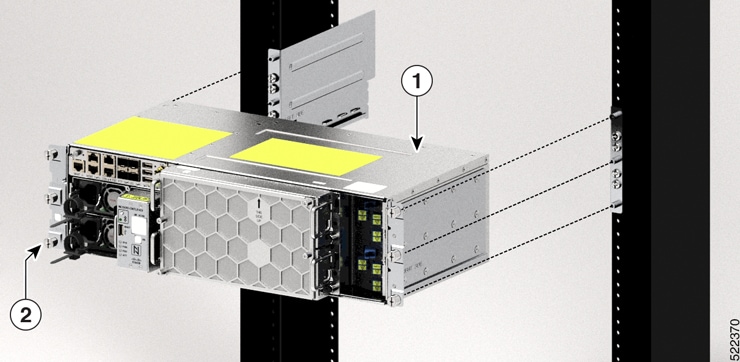
Insert the chassis onto the slide rails assembled on the rack.

Figure 10. Mounting the Chassis on the Rack

1

Cisco NCS 1010 chassis

2

Captive screws

Step 3

After the chassis is completely inserted, tighten the captive screws into the standoffs available on each side of the slide rail, using a number-2 Phillips screwdriver to a torque value of 1.5 N-m (13.3 lbs-in).