Cisco NCS 1020 Chassis Overview
The Cisco NCS 1020 is a new Wavelength Division Multiplexing (WDM) System that is optimized for ZR/ZR+ WDM router interfaces. Its salient features are:
-
Operates as an integrated optical layer Reconfigurable Optical Add-Drop Multiplexer (ROADM) and Amplifier system to support Point-to-Point (P2P), Ring, and Mesh network architectures, complete with add/drop capabilities.
-
Offers transmission versatility by supporting multiple coherent sources such as:
-
400G digital coherent ZR/ZR+ optics (-10dBm output power)
-
High-performance DCO transponders such as 1.2T and 2-QDD-C cards that use high GBaud rates.
-
-
Supports C-band only and C+L-band WDM transmission to maximize capacity.

Note
In R24.2.11, the Cisco NCS 1020 supports only C-band networks.
Cisco NCS 1020 is a 10RU chassis that has an in-built External Interface Timing Unit (EITU) and the following field-replaceable modules.
-
One Solid State Drive (SSD)
-
Two controllers (active and backup)
-
Two power supply units (PSUs)
-
Eight fan trays (four NCS1010-FAN trays and four NCS1020-FAN trays)

Note
In this chapter, "front fan tray" refers to the NCS1010-FAN tray, "rear fan tray" refers to the NCS1020-FAN tray, and "filler fan tray" refers to the NCS1020-FAN-BLANK tray. Front fan trays and rear fan trays contain a different set of fan units. Slots for the front fan trays and rear fan trays aren’t interchangeable.
-
Ten line cards (two NCS 1010 line cards and eight NCS 1014 line cards).

Note
NCS 1010 line card slots and NCS 1014 line card slots aren’t interchangeable. In this chapter, Type 1 line card refers to "NCS 1010 line card" and Type 2 line card refers to "NCS 1014 line card".
The NCS 1020 chassis supports the following line cards:
|
Line Card |
Description |
Release |
|---|---|---|
|
Type 1 Line Cards |
||
|
C-band Optical Line Terminal without Raman |
Cisco IOS XR Release 24.2.11 |
|
|
C-band Optical Line Terminal without Raman, Enhanced |
Cisco IOS XR Release 24.2.11 |
|
|
Type 2 Line Card |
||
|
NCS 1000 16-port Colorless Direct attach LC with EDFA, C-band |
Cisco IOS XR Release 24.2.11 |
|
In this chapter, the following table lists the references that are used for each line card.
|
Line Card |
Referred As |
|---|---|
|
NCS1K-OLT-C= |
OLT-C |
|
NCS1K-E-OLT-C= |
E-OLT-C |
|
NCS1K14-CCMD-16-C= |
CCMD-16-C |
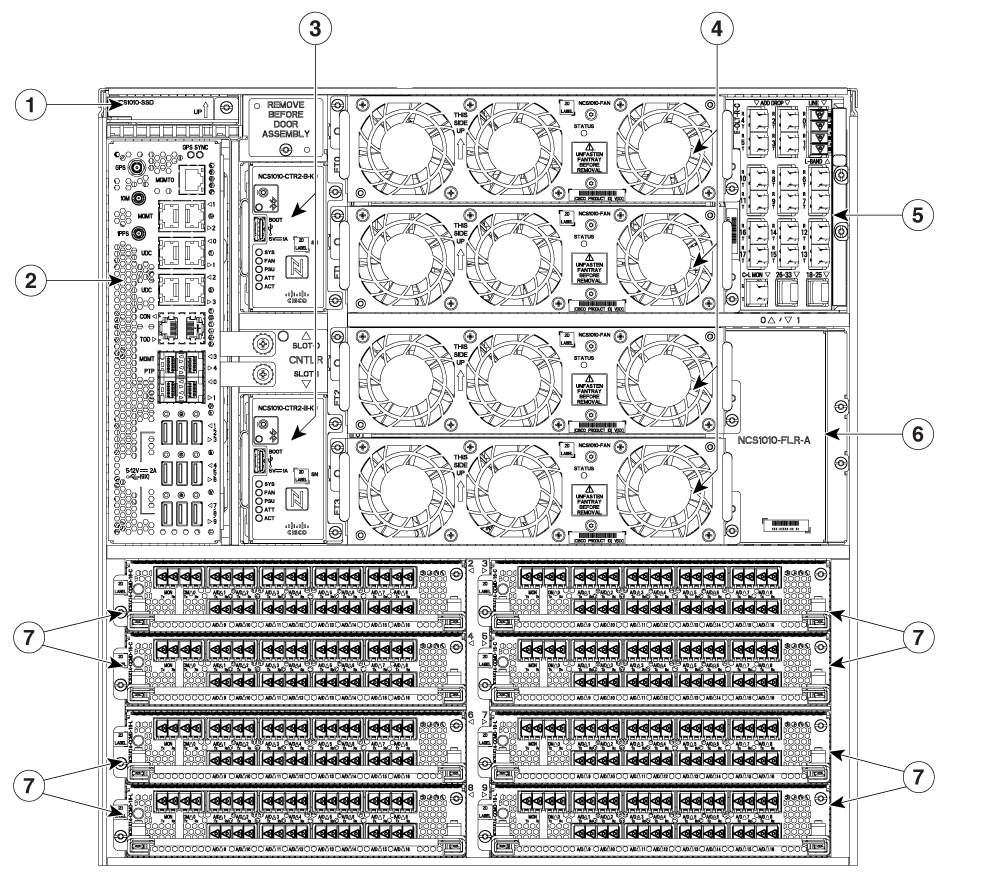
The chassis has the EITU, controller, SSD, front fan trays, and line card slots on the front side.
The following image shows a fully loaded Cisco NCS 1020 chassis. The chassis supports the Type 1 line cards in slots 0 and 1 and the Type 2 line cards in slots 2 to 9. The controllers occupy CNTLR slots 0 and 1.
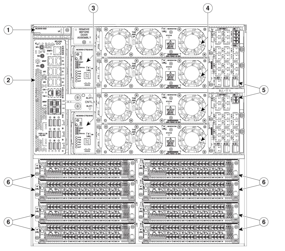
|
1 |
SSD |
4 |
Front fan trays |
|
2 |
EITU |
5 |
Type 1 line cards |
|
3 |
Controllers |
6 |
Type 2 line cards |
The chassis has the PSUs and rear fan trays on the rear side.
The following image is the rear view of the Cisco NCS 1020. In the chassis, the rear fan trays in the slots FT4 and FT5 cool the Type 2 line cards in slots from 2 to 5 at the front. Fan trays in slots FT6 and FT7 cool the Type 2 line cards in slots from 6 to 9 at the front.
 Note |
Filler fan trays can only be used when all the Type 2 card slots at the front are populated with Type 2 filler cards. Even if there’s only one Type 2 line card in the Type 2 card slots, you must install rear fan trays in both the rear slots. For more information, see Install the Rear Fan/Filler Fan Trays. |

|
1 |
PSUs |
2 |
Rear fan trays |
Airflow in the Cisco NCS 1020 Chassis
The Cisco NCS 1020 chassis has a front-to-rear airflow mechanism to ventilate the modules. It delivers cooling through five different channels.
The following image shows the airflow channels in a fully loaded NCS 1020 chassis.

The following table describes the airflow in a fully loaded NCS 1020 chassis.
|
Callout |
Airflow Channel |
Airflow Process |
|---|---|---|
|
1 |
Channel 1 |
Pair of front fan trays at top cool the Type 1 line card and controller in slot 0. |
|
2 |
Channel 2 |
Pair of front fan trays at bottom cool the Type 1 line card and controller in slot 1. |
|
3 |
Channel 3 |
Rear fan trays in slots FT4 and FT5 cool the Type 2 line cards in slots 2, 3, 4, and 5. |
|
4 |
Channel 4 |
Rear fan trays in slots FT6 and FT7 cool the Type 2 line cards in slots 6, 7, 8, and 9. |
|
5 |
Channel 5 |
Built-in fans in the PSUs cool the EITU and SSD on the front. |
External Interface Timing Unit
The External Interface Timing Unit (EITU) manages the control plane interfaces and includes all user external interfaces (timing and management). It is connected to the controller with a redundant 10 G Ethernet bus.
EITU is a fixed part of the chassis and it is not removable or replaceable in the field.
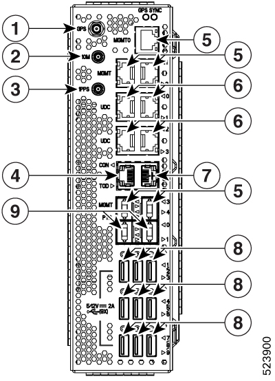
The following is the list of the available interfaces:
|
1 |
Coaxial connector for GPS antenna RF input (with 5 V antenna power, if necessary) (1x) |
||
|
2 |
Coaxial connector for 10 MHz sync signal (bidirectional) (1x) |
||
|
3 |
Coaxial connector for 1PPS sync signal (bidirectional) (1x) |
||
|
4 |
Console/Universal Asynchronous Receiver/Transmitter (UART) Interface (1x) |
||
|
5 |
10/100/1000 RJ-45 Ethernet management ports and Interconnection Link (ILINK) (5x)
|
||
|
6 |
SFP for 1 GE optical User Data Channels (UDC) (4x) |
||
|
7 |
RJ-45 for 1588 TOD (1x) |
||
|
8 |
USB 2.0 type A, 1.8 A max at 5 V / 12 V (9x)
|
||
|
9 |
SFP for 1 GE optical PTP port (1588 and SyncE) (2x) |









 Feedback