Configuring the Pluggable Module

This chapter contains the following sections:

LPWA Interface Configuration

The P-LPWA-800 and P-LPWA-900 modules can be managed by command line interface (CLI), or the Cisco IOS XE Web User Interface (WebUI).


Note

GPS is mandatory for the Common Packet Forwarder (CPF) application to work. Please connect the Lora module GPS antenna, and check the GPS status using the below command before installing the CPF application.
Router#show lorawan 0/1/0 gps
Recorded GNSS Info at 2022-09-13 19:20:50 UTC

GNSS Location:
Latitude: 37 Deg 25 Min 5.937 Sec North (37.418316)
Longitude: 121 Deg 55 Min 9.714 Sec West (-121.919365)
Height: 37.0m

Router#

The following is an example of GPS Configuration:

interface LORAWAN0/1/0
no ip address
common-packet-forwarder profile
country UNITEDSTATES
region-channel-plan US915
gateway-id 69
lns-ip 172.27.127.209
lns-port 6080
log-level xdebug lines 240
gps enable
cpf enable
arp timeout 0
no mop enabled
no mop sysid
end

To clear the GPS information use the following command:

Router#clear lorawan 0/1/0 cpf location-info
Router#

Common Packet Forwarder Configuration Steps

Additional information can be found at Managing Packet Forwarder.

Follow these steps to configure the interface.

Procedure

  Command or Action Purpose

Step 1

configure terminal

Example:

Router# configure terminal 

Enters global configuration mode.

Step 2

int loraWAN interface

Example:

Router(config)# int loraWAN 0/1/0 

Enters LoraWan interface config mode.

Step 3

common-packet-forwarder profile

Example:

Router(config-if)# common-packet-forwarder profile

Configures parameters for the CPF.

Step 4

region-channel-plan <number>

Example:

Router(config-if-lorawan-cpf)#region-channel-plan US915

Configures the regional channel plan code.

Step 5

gateway-id <number>

Example:

Router(config-if-lorawan-cpf)# gateway-id 69 

Configures gateway id used for CPF.

Step 6

lns-ip <ip-address>

Example:

Router(config-if-lorawan-cpf)#lns-ip 172.27.127.209 

Configures Lora network server IP address.

Step 7

lns-port <port-number>

Example:

Router(config-if-lorawan-cpf)# lns-port 6080 

Configures Lora network server port number.

Step 8

cpf enable

Example:

Router(config-if-lorawan-cpf)# cpf enable 

Starts the CPF.

Note 
This configuration will ONLY take effect after exiting from current sub-mode.

Step 9

exit

Example:

Router(config-if-lorawan-cpf)# exit

Exits the CPF profile block and updates the configuration.

Step 10

exit

Example:

Router(config-if)# exit 

Exits from interface config mode.

Step 11

exit

Example:

Router# exit 

Exits from config mode.

Default Configuration

The following is an example of a default configuration for the lorawan interface.

Router#sh run int lorawan 0/3/0
Building configuration...

Current configuration : 192 bytes
!
interface LORAWAN0/3/0
 no ip address
 common-packet-forwarder profile
  gateway-id 69
  lns-ip 172.27.127.209
  lns-port 6080
  cpf enable
 arp timeout 0
 no mop enabled
 no mop sysid
end
Router#

Configuring the Interface using the WebUI

Use the following steps to configure the Cisco lorawan interface through the WebUI.

Procedure


Step 1

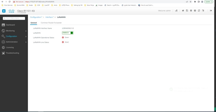
After launching the WebUI, navigate to Configuration > LoRaWAN.

For details about using the WebUI, see Web User Interface (WebUI) in the IR1101 Software Configuration Guide.

Step 2

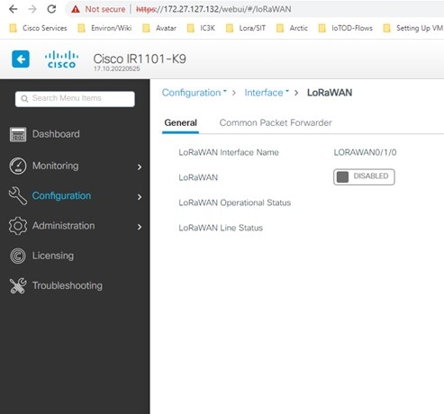
Double click on the LoRaWAN interface.
Step 3

Enable the Cisco lorawan interface.

Step 4

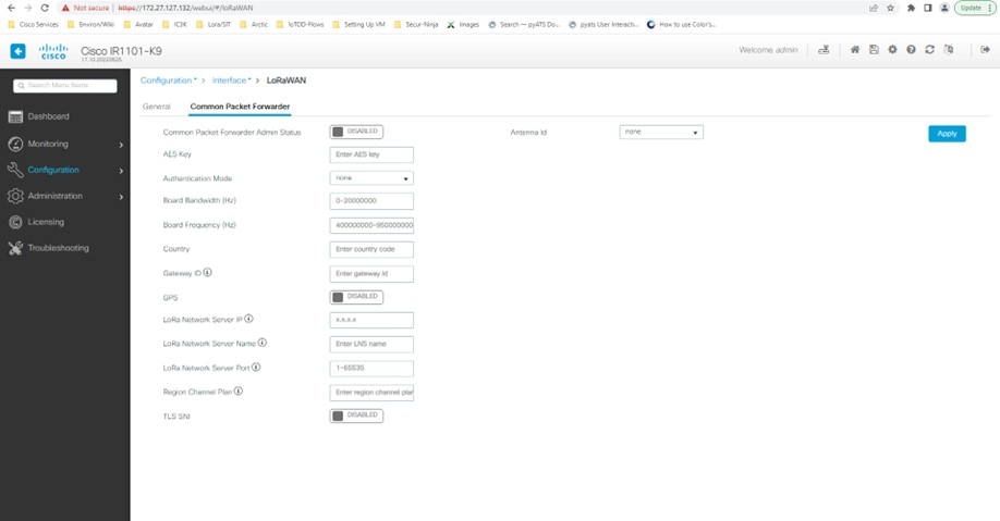
Click on the Common Packet Forwarder tab to add the CPF configuration.
Step 5

Add the CPF configuration and set the Common Packet Forwarder Admin Status to ENABLED.


What to do next

For the Application deployment process using the Local Manager, please refer to Cisco IOx Local Manager Workflows.

Common Packet Forwarder Application Hosting for LoRa Technology

To configure application hosting, enable IOx and configure a VirtualPortGroup to a Layer 3 data port. These steps are described in the following sections.

Enable IOx

Perform the following steps to enable access to Cisco IOx Local Manager. IOx Local Manager provides a web-based user interface that you can use to manage, administer, monitor, and troubleshoot apps on the host system, and to perform a variety of related activities.

Procedure

  Command or Action Purpose

Step 1

enable

Example:

Router>enable

Enable privileged EXEC mode

Step 2

configure terminal

Example:

Router#configure terminal 

Enters global configuration mode.

Step 3

iox

Example:

Router(config)#iox 

Enable Cisco IOx

Step 4

ip http server

Example:

Router(config)#ip http server

Enable the HTTP server on your IPv4 or IPv6 system.

Step 5

ip http secure-server

Example:

Router(config)#ip http secure-server

Enable a secure HTTP (HTTPS) server.

Step 6

username name privilege level password {0 | 7 | user-password } encrypted-password

Example:

Router(config)#username cisco privilege 15 password 0 cisco

Establish a username-based authentication system and privilege level. The username privilege level must be configured as 15.

Step 7

end

Example:

Router(config-if)#end 

Exit the interface configuration mode and return to the privileged EXEC mode.

Configure a VirtualPortGroup to a Layer 3 Data Port

Multiple Layer 3 data ports can be routed to one or more VirtualPortGroups or containers. A VirtualPortGroup interface is a virtual interface that connects the application hosting network to the IOS routing domain. VirutalPortGroups and Layer 3 data ports must be on different subnets.

Procedure

  Command or Action Purpose

Step 1

enable

Example:

Router> enable

Enable privileged EXEC mode.

Step 2

configure terminal

Example:

Router# configure terminal 

Enters global configuration mode.

Step 3

ip routing

Example:

Router(config)#ip routing 

Enable IP routing. The ip routing command must be enabled to allow external routing on Layer 3 data ports.

Step 4

interface type number

Example:

Router(config)#interface gigabitethernet 0/0/0

Configure an interface and enter interface configuration mode.

Step 5

no switchport

Example:

Router(config-if)#no switchport

Place the interface in Layer 3 mode and make it operate more like a router interface than a switch port.

Step 6

ip address ip-address mask

Example:

Router(config)#ip address 10.1.1.1 255.255.255.0

Configure an IP address for the interface.

Step 7

exit

Example:

Router(config-if)#exit 

Exit interface configuration mode and return to global configuration mode.

Step 8

interface type number

Example:

Router(config)#interface virtualportgroup 0

Configure an interface and enter interface configuration mode.

Step 9

ip address ip-address mask

Example:

Router(config-if)#ip address 192.168.0.1 255.255.255.0 

Configure an IP address for the interface.

Step 10

end

Example:

Router(config-if)#end 

Exit interface configuration mode and return to global configuration mode.

Configure Application Networking

Application vNIC interface is the standard Ethernet interface inside the container that connects to the platform data plane for the application to send and receive packets.

Procedure

  Command or Action Purpose

Step 1

enable

Example:

Router> enable

Enable privileged EXEC mode

Step 2

configure terminal

Example:

Router#configure terminal 

Enters global configuration mode, and then enter configuration commands, one per line. Press CTRL-Z when you are finished entering configuration commands.

Step 3

app-hosting appid app1

Example:

Router(config)#app-hosting appid app1

Configure the application and enter the application configuration mode.

Step 4

app-vnic options

Example:

Router(config-app-hosting)#app-vnic gateway0 virtualportgroup 0 guest-interface 0

Configure the application interface and the gateway of the application.

Step 5

guest-ipaddress ip-address mask

Example:

Router(config-app-hosting-gateway0)#guest-ipaddress 192.168.0.2 netmask 255.255.255.0

Configure the application Ethernet interface IP address.

Step 6

app-default-gateway options

Example:

Router(config-app-hosting-gateway0)#app-default-gateway 192.168.0.1 guest-interface 0

Configure the default gateway for the application.

Step 7

end

Example:

Router#end

Exit the global configuration mode and return to the privileged EXEC mode.

Application Lifecycle Management

This section describes the process of installing and uninstalling apps.

Procedure

  Command or Action Purpose

Step 1

enable

Example:

Router> enable

Enable privileged EXEC mode

Step 2

configure terminal

Example:

Router# configure terminal 

Enters global configuration mode, and then enter configuration commands, one per line. Press CTRL-Z when you are finished entering configuration commands.

Step 3

app-hosting install appid application-name package package-path

Example:

Router(config)#app-hosting install appid CPFAPP package flash:cpfv5.tar

Installs an app from the specified location. The app can be installed from any local storage location such as flash, bootflash, and usbflash0.

Step 4

app-hosting activate appid application-name

Example:

Router#app-hosting activate appid CPFAPP

Activate the application. This command validates all application resource requests, and if all resources are available, activates the application. If all resources are not available, the activation fails.

Step 5

app-hosting start appid application-name

Example:

Router#app-hosting start appid CPFAPP

Start the application. This command activates the application start-up scripts.

Step 6

app-hosting stop appid application-name

Example:

Router#app-hosting stop appid CPFAPP

Stop the application.

Step 7

app-hosting deactivate appid application-name

Example:

Router#app-hosting deactivate appid CPFAPP

Deactivates all resources that are allocated for the application.

Step 8

app-hosting uninstall appid application-name

Example:

Router(config)#app-hosting uninstall appid CPFAPP

Uninstalls all packaging and images that are stored and removes all changes and updates to the application.

Verifying the Application Hosting Configuration

This section shows commands to verify the application hosting configuration.

Display the status of all IOx services

Router#show iox-service

IOx Infrastructure Summary:
---------------------------
IOx service (CAF)              : Running
IOx service (HA)               : Not Supported
IOx service (IOxman)           : Running
IOx service (Sec storage)      : Running
Libvirtd 5.5.0                 : Running
Dockerd v19.03.13-ce           : Running

Router#

Display detailed information about the application

Router#show app-hosting detail
pp id                         : cp
Owner                         : iox
State                         : RUNNING

Application	
  Type                        : docker
  Name                        : cpf
  Version                     : vl
  Description                 : buildkit.dockerfile.vO
  Author                      :
  Path                        : bootflash:cpfv5.tar
  URL Path                    :
  Multicast                   : yes
 Activated profile name       :custom

Resource reservation
  Memory                      :128 MB
  Disk                        :10 MB
  CPU                         :400 units
  CPU-percent                 :35 %
  VCPU                        :1

Platform resource profiles
  Profile Name	        	CPU(unit)  Memory(MB)  Disk(MB)
  -------------------------------------------------------------

Attached devices
  Type	           Name	               Alias
  ------------------------------------------
  serial/shell     iox_console_shell   serialO 
  serial/aux       iox_console_aux     serial1 
  serial/syslog    iox_syslog          serial2 
  serial/trace     iox_trace           serial3

Network interfaces
----------------------------------------------
ethO:
  MAC address               : 52:54:dd:f2:f4:87
  IPv4 address              : 192.168.0.9
  IPv6 address              ::
  Network name              : VPGO


Docker
------
Run-time information 
  Command                   :
  Entry-point               : /station/cpf
  Run options in use        : --device /dev/lorawan_ttyl:/dev/ttyACMO -v /bootflash/lorawan_0:/cpf/ 
  Package run options       : 

Application health information 
  Status                    : 0
  Last probe error          : 
  Last probe output         :

Display the list of applications and their statuses

Router#show app-hosting list
App id State
---------------------------------------------
CPFAPP RUNNING

Use the Console command to connect to the application

Press Ctrl+C three times to disconnect from the console.

Router# app-hosting app-hosting connect appid CPFAPP console 
Connected to appliance. Exit using ^c^c^c
root@ir510-lxc:~#
root@ir510-lxc:~#
root@ir510-lxc:~#
root@ir510-lxc:~#
root@ir510-lxc:~#
root@ir510-lxc:~# IR11014006#

Actility Packet Forwarder Application Hosting for LoRa Technology

The following are prerequisites for configuring application hosting. There is a new process for ssh key sharing between the container and host.

Perform the following on the host:

Add a username and password.

config terminal 
username actility privilege 15 password 0 Actility_Password 
exit 

Run the docker container with the following options:

  • device /dev/ttyACM0:/dev/ttyACM0

  • env HOST_IP_ADDR=192.168.42.11

  • env HOST_USER=actility

  • env HOST_SETUP_PASSWORD=actilityPassword

In the docker container options above, note the default ip address, username, and password. Change these to match your configuration.


Note

After the first installation you do not have a password for the actility user (username actility privilege 15). If you want to reinstall ThingPark Long Range Relay (LRR) software, you will have to set username actility privilege 15 password 0 actilityPassword again.

To configure application hosting, enable IOx and configure a VirtualPortGroup to a Layer 3 data port. These steps are described in the following sections.

Enable IOx

Perform the following steps to enable access to Cisco IOx Local Manager. IOx Local Manager provides a web-based user interface that you can use to manage, administer, monitor, and troubleshoot apps on the host system, and to perform a variety of related activities.

Procedure

  Command or Action Purpose

Step 1

enable

Example:

Router>enable

Enable privileged EXEC mode.

Step 2

configure terminal

Example:

Router#configure terminal 

Enters global configuration mode.

Step 3

iox

Example:

Router(config)#iox 

Enable Cisco IOx.

Step 4

ip http server

Example:

Router(config)#ip http server

Enable the HTTP server on your IPv4 or IPv6 system.

Step 5

ip http secure-server

Example:

Router(config)#ip http secure-server

Enable a secure HTTP (HTTPS) server.

Step 6

username name privilege level password {0 | 7 | user-password } encrypted-password

Example:

Router(config)#username cisco privilege 15 password 0 cisco

Establish a username-based authentication system and privilege level. The username privilege level must be configured as 15.

Step 7

end

Example:

Router(config-if)#end 

Exit the interface configuration mode and return to the privileged EXEC mode.

Configure a VirtualPortGroup to a Layer 3 Data Port

Multiple Layer 3 data ports can be routed to one or more VirtualPortGroups or containers. A VirtualPortGroup interface is a virtual interface that connects the application hosting network to the IOS routing domain. VirutalPortGroups and Layer 3 data ports must be on different subnets.

Procedure

  Command or Action Purpose

Step 1

enable

Example:

Router> enable

Enable privileged EXEC mode.

Step 2

configure terminal

Example:

Router# configure terminal 

Enters global configuration mode.

Step 3

ip routing

Example:

Router(config)#ip routing 

Enable IP routing. The ip routing command must be enabled to allow external routing on Layer 3 data ports.

Step 4

interface type number

Example:

Router(config)#interface gigabitethernet 0/0/0

Configure an interface and enter interface configuration mode.

Step 5

no switchport

Example:

Router(config-if)#no switchport

Place the interface in Layer 3 mode and make it operate more like a router interface than a switch port.

Step 6

ip address dhcp

Example:

Router(config)#ip address dhcp

Configure an IP address for the interface.

Step 7

exit

Example:

Router(config-if)#exit 

Exit interface configuration mode and return to global configuration mode.

Step 8

interface type number

Example:

Router(config)#interface virtualportgroup 0

Configure an interface and enter interface configuration mode.

Step 9

ip address ip-address mask

Example:

Router(config-if)#ip address 192.168.2.1 255.255.255.0 

Exit interface configuration mode and return to global configuration mode.

Step 10

end

Example:

Router(config-if)#end 

Exit interface configuration mode and return to global configuration mode.

Configure Application Networking

Application vNIC interface is the standard Ethernet interface inside the container that connects to the platform data plane for the application to send and receive packets.

Procedure

  Command or Action Purpose

Step 1

enable

Example:

Router> enable

Enable privileged EXEC mode.

Step 2

configure terminal

Example:

Router#configure terminal 

Enters global configuration mode, and then enter configuration commands, one per line. Press CTRL-Z when you are finished entering configuration commands.

Step 3

app-hosting appid app1

Example:

Router(config)#app-hosting appid app1

Configure the application and enter the application configuration mode.

Step 4

app-vnic options

Example:

Router(config-app-hosting)#app-vnic gateway0 virtualportgroup 0 guest-interface 0

Configure the application interface and the gateway of the application.

Step 5

guest-ipaddress ip-address mask

Example:

Router(config-app-hosting-gateway0)#guest-ipaddress 192.168.2.9 netmask 255.255.255.0

Configure the application Ethernet interface IP address.

Step 6

app-default-gateway options

Example:

Router(config-app-hosting-gateway0)#app-default-gateway 192.168.2.1 guest-interface 0

Configure the default gateway for the application.

Step 7

end

Example:

Router#end

Exit the global configuration mode and return to the privileged EXEC mode.

Application Lifecycle Management

This section describes the process of installing and uninstalling apps.

Procedure

  Command or Action Purpose

Step 1

enable

Example:

Router> enable

Enable privileged EXEC mode.

Step 2

configure terminal

Example:

Router# configure terminal 

Enters global configuration mode, and then enter configuration commands, one per line. Press CTRL-Z when you are finished entering configuration commands.

Step 3

app-hosting install appid application-name package package-path

Example:

Router(config)#app-hosting install appid APFAPP package flash:actility_tar_gz.tar

Installs the app from the specified location. The app can be installed from any local storage location such as flash, bootflash, and usbflash0.

Step 4

app-hosting activate appid application-name

Example:

Router#app-hosting activate appid APFAPP

Activate the application. This command validates all application resource requests, and if all resources are available, activates the application. If all resources are not available, the activation fails.

Step 5

app-hosting start appid application-name

Example:

Router#app-hosting start appid APFAPP

Start the application. This command activates the application start-up scripts.

Step 6

app-hosting stop appid application-name

Example:

Router#app-hosting stop appid APFAPP

Stop the application.

Step 7

app-hosting deactivate appid application-name

Example:

Router#app-hosting deactivate appid APFAPP

Deactivates all resources that are allocated for the application.

Step 8

app-hosting uninstall appid application-name

Example:

Router(config)#app-hosting uninstall appid APFAPP

Uninstalls all packaging and images that are stored and removes all changes and updates to the application.

Verifying the Application Hosting Configuration

This section shows commands to verify the application hosting configuration.

Display the status of all IOx services

Router#show iox-service

IOx Infrastructure Summary:
---------------------------
IOx service (CAF)              : Running
IOx service (HA)               : Not Supported
IOx service (IOxman)           : Running
IOx service (Sec storage)      : Running
Libvirtd 5.5.0                 : Running
Dockerd v19.03.13-ce           : Running

Router#

Display detailed information about the application

Router#show app-hosting detail
 App id                 : APFC1
Owner                  : iox
State                  : RUNNING
Application
  Type                 : docker
  Name                 : base-rootfs-runtime-actility
  Version              : latest
  Description          : Actility LRR
  Author               : Actility
  Path                 : bootflash:actility_lrr_76.tar.gz
  URL Path             :
  Multicast            : yes
Activated profile name : custom

Resource reservation
  Memory               : 64 MB
  Disk                 : 2 MB
  CPU                  : 50 units
  CPU-percent          : 5 %
  VCPU                 : 1

Platform resource profiles
  Profile Name                  CPU(unit)  Memory(MB)  Disk(MB)
  --------------------------------------------------------------

Attached devices
  Type              Name               Alias
  ---------------------------------------------
  serial/shell     iox_console_shell   serial0
  serial/aux       iox_console_aux     serial1
  serial/syslog    iox_syslog          serial2
  serial/trace     iox_trace           serial3

Network interfaces
   ---------------------------------------
eth0:
   MAC address         : 52:54:dd:16:24:0a
   IPv4 address        : 192.168.2.9
   IPv6 address        : ::
   Network name        : VPG0


Docker
------
Run-time information
  Command              :
  Entry-point          :  /etc/init.d/lrr_iox_top start
  Run options in use   : --device /dev/ttyACM0:/dev/ttyACM0 --env HOST_IP_ADDR=192.168.2.1 --env HOST_USER=actility --env HOST_SETUP_PASSWORD=actilityPassword
  Package run options  :
Application health information
  Status               : 0
  Last probe error     :
  Last probe output    :

Router#

Display the list of applications and their statuses

Router#show app-hosting list
App id State
---------------------------------------------
APFAPP RUNNING

Use the following command to connect to the application

Press Ctrl+C three times to disconnect the console.

Router# app-hosting app-hosting connect appid APFAPP session 
/home/actility/var/log/lrr

/var/volatile/log/_LRRLOG # pwd
/home/actility/var/log/lrr

/var/volatile/log/_LRRLOG # ls -lrt
-rw-r--r--    1 root     root            19 Jul  7 0646 SHELL.log
-rw-r--r--    1 root     support         53 Jul  7 0647 suplog.log
-rw-r--r--    1 root     support         99 Jul  7 0648 pkiconfig.txt
-rw-r--r--    1 root     root           430 Jul  7 0720 lrr_startup_service.log
-rw-r--r--    2 root     root          1620 Jul  7 0721 gwmgr_04.log
-rw-r--r--    2 root     root          1620 Jul  7 0721 gwmgr.log
-rw-r--r--    1 root     root          1657 Jul  7 0721 radioparams.txt
-rw-r--r--    1 root     root          2227 Jul  7 0721 logicchan.txt
-rw-r--r--    1 root     root          1118 Jul  7 1721 stat.html
-rw-r--r--    2 root     root         50515 Jul  7 1721 TRACE_04.log
-rw-r--r--    2 root     root         50515 Jul  7 1721 TRACE.log
-rw-r--r--    1 root     root            64 Jul  7 1723 lrcstatuslink.txt
/var/volatile/log/_LRRLOG #

Show app hosting in the running configuration

Router#show running-config | sec app-hosting
 action 2 cli command "app-hosting stop appid APFC1"
 action 4 cli command "app-hosting start appid APFC1"
app-hosting appid APFC1
 app-vnic gateway0 virtualportgroup 0 guest-interface 0
  guest-ipaddress 192.168.2.9 netmask 255.255.255.0
 app-default-gateway 192.168.2.1 guest-interface 0
 app-resource docker
  run-opts 1 "--device /dev/ttyACM0:/dev/ttyACM0"
  run-opts 2 "--env HOST_IP_ADDR=192.168.2.1"
  run-opts 3 "--env HOST_USER=actility"
  run-opts 4 "--env HOST_SETUP_PASSWORD=actilityPassword"
Router#

Sample Running Configuration

The following example if from an IR1101.

Router#show running-config brief
Building configuration...

Current configuration  7651 bytes
!
! Last configuration change at 072004 UTC Thu Jul 7 2022 by actility
! NVRAM config last updated at 065725 UTC Thu Jul 7 2022 by actility
!
version 17.9
service timestamps debug datetime msec
service timestamps log datetime msec
service call-home
platform qfp utilization monitor load 80
platform hardware throughput level 250M
platform punt-keepalive disable-kernel-core
!
hostname Router
!
boot-start-marker
boot system flashir1101-universalk9.S2C.SSA.bin
boot-end-marker
!
!
aaa new-model
!
!
aaa authentication login default local
aaa authorization exec default local
aaa authorization network FlexVPN_Author local
!
!
aaa session-id common
!
!
login block-for 60 attempts 3 within 30
login delay 3
login on-success log
ipv6 unicast-routing
!
!
subscriber templating
!
!
multilink bundle-name authenticated
!
!
crypto pki trustpoint TP-self-signed-1150468717
 enrollment selfsigned
 subject-name cn=IOS-Self-Signed-Certificate-1150468717
 revocation-check none
 rsakeypair TP-self-signed-1150468717
!
crypto pki trustpoint SLA-TrustPoint
 enrollment pkcs12
 revocation-check crl
!
crypto pki trustpoint ActilityTP-slrc
 enrollment terminal
 revocation-check none
!
crypto pki trustpoint ActilityTP
 enrollment pkcs12
 revocation-check crl
 rsakeypair ActilityTP
!
crypto pki trustpoint ActilityTP-rrr1
 revocation-check crl
!
!
crypto pki certificate map FlexVPN_Cert_Map 1
 subject-name co slrc1_prod-us_actility-tpe-ope
!
crypto pki certificate map FlexVPN_Cert_Map 2
 subject-name co slrc2_prod-us_actility-tpe-ope
!
crypto pki certificate chain TP-self-signed-1150468717
 certificate self-signed 01
crypto pki certificate chain SLA-TrustPoint
 certificate ca 01
crypto pki certificate chain ActilityTP-slrc
 certificate ca 61A845069BBFF60B
crypto pki certificate chain ActilityTP
 certificate 06BF5FDCF5EBD17C
 certificate ca 3A96CABF858AAD9A
crypto pki certificate chain ActilityTP-rrr1
 certificate ca 00F35AC229699BABA8
!
!
no license feature hseck9
license udi pid IR1101-K9 sn FCW24160HQ7
license boot level network-advantage
memory free low-watermark processor 45069
!
diagnostic bootup level minimal
!
spanning-tree extend system-id
!
!
username admin privilege 15 password 0 cisco
username iox privilege 15 password 0 iox
username dockeruser
username actility privilege 15
!
redundancy
!
crypto ikev2 authorization policy FlexVPN_Author_Policy
!
!
crypto ikev2 profile FlexVPN_IKEv2_Profile
 match certificate FlexVPN_Cert_Map
 identity local dn
 authentication remote rsa-sig
 authentication local rsa-sig
 pki trustpoint ActilityTP sign
 pki trustpoint ActilityTP-rrr1 verify
 pki trustpoint ActilityTP-slrc verify
 dpd 30 3 periodic
 aaa authorization group cert list FlexVPN_Author FlexVPN_Author_Policy
!
crypto ikev2 dpd 30 3 periodic
crypto ikev2 fragmentation mtu 1260
!
controller Cellular 0/3/0
!
!
vlan internal allocation policy ascending
!
!
crypto ipsec transform-set FlexVPN_IPsec_Transform_Set esp-aes 256 esp-sha256-hmac
 mode tunnel
!
crypto ipsec profile FlexVPN_IPsec_Profile
 set transform-set FlexVPN_IPsec_Transform_Set
 set ikev2-profile FlexVPN_IKEv2_Profile
!
!
interface Tunnel201
 ip address negotiated
 ip nat outside
 ipv6 enable
 tunnel source GigabitEthernet0/0/0
 tunnel mode ipsec dual-overlay
 tunnel destination 52.200.161.236
 tunnel path-mtu-discovery
 tunnel protection ipsec profile FlexVPN_IPsec_Profile
!
interface Tunnel202
 ip address negotiated
 ip nat outside
 ipv6 enable
 tunnel source GigabitEthernet0/0/0
 tunnel mode ipsec dual-overlay
 tunnel destination 54.226.90.83
 tunnel path-mtu-discovery
 tunnel protection ipsec profile FlexVPN_IPsec_Profile
!
interface VirtualPortGroup0
 ip address 192.168.2.1 255.255.255.0
 ip nat inside
 no mop enabled
 no mop sysid
!
interface GigabitEthernet0/0/0
 ip dhcp client client-id ascii cisco-ac4a.67f9.ae00-Gi0/0/0
 ip address dhcp
 ip nat outside
 ipv6 dhcp client request vendor
 ipv6 address dhcp
 ipv6 address autoconfig
 ipv6 enable
!
interface FastEthernet0/0/1
!
interface FastEthernet0/0/2
!
interface FastEthernet0/0/3
!
interface FastEthernet0/0/4
!
interface GigabitEthernet0/0/5
!
interface Cellular0/3/0
 description backup_WAN
 ip address negotiated
 ip nat outside
 ip tcp adjust-mss 1460
 load-interval 30
 shutdown
 dialer in-band
 dialer idle-timeout 0
 dialer-group 1
 ipv6 enable
 pulse-time 1
!
interface Cellular0/3/1
 no ip address
!
interface Vlan1
 no ip address
!
interface Async0/2/0
 no ip address
 encapsulation scada
!
interface LORAWAN0/1/0
 no ip address
 shutdown
 arp timeout 0
 no mop enabled
 no mop sysid
!
iox
ip forward-protocol nd
ip tcp selective-ack
ip tcp mss 1460
ip tcp window-size 131072
ip http server
ip http auth-retry 3 time-window 1
ip http authentication local
ip http secure-server
ip http client source-interface GigabitEthernet0/0/0
ip tftp source-interface GigabitEthernet0/0/0
ip nat inside source list Tunnel201 interface Tunnel201 overload
ip nat inside source list Tunnel202 interface Tunnel202 overload
ip nat inside source list internetacces_Fromdocker interface GigabitEthernet0/0/0 overload
ip nat inside source list internetacces_Fromdocker_cell interface Cellular0/3/0 overload
ip route 10.102.12.0 255.255.255.0 Tunnel201
ip route 10.102.22.0 255.255.255.0 Tunnel202
ip ssh bulk-mode 131072
ip ssh version 2
ip ssh pubkey-chain
  username actility
   key-hash ecdsa-sha2-nistp256 FA249B09C77A121A9759A0FC724F58A8 root@a89e080e0c1e
ip ssh server algorithm publickey ecdsa-sha2-nistp256
ip scp server enable
!
!
ip access-list extended Tunnel201
 10 permit ip host 192.168.2.9 host 10.102.12.10
ip access-list extended Tunnel202
 10 permit ip host 192.168.2.9 host 10.102.22.10
ip access-list extended internetacces_Fromdocker
 10 permit ip 192.168.2.0 0.0.0.255 host 8.8.8.8
 11 permit ip 192.168.2.0 0.0.0.255 host 52.200.161.236
ip access-list extended internetacces_Fromdocker_cell
 10 permit ip host 192.168.2.9 host 8.8.8.8
!
ip sla 1
 icmp-echo 8.8.8.8 source-interface GigabitEthernet0/0/0
ip sla schedule 1 life forever start-time now
ip sla 2
 icmp-echo 8.8.8.8 source-interface Cellular0/3/0
ip sla schedule 2 life forever start-time now
ip access-list standard 1
 11 permit any
dialer-list 1 protocol ip permit
!
!
control-plane
!
!
line con 0
 stopbits 1
line 0/0/0
line 0/2/0
line vty 0 4
 transport input ssh
line vty 5 14
 transport input ssh
!
call-home
 ! If contact email address in call-home is configured as sch-smart-licensing@cisco.com
 ! the email address configured in Cisco Smart License Portal will be used as contact email address to send SCH notifications.
 contact-email-addr sch-smart-licensing@cisco.com
 profile "CiscoTAC-1"
  active
  destination transport-method http
ntp server 0.pool.ntp.org
ntp server 1.pool.ntp.org
ntp server 2.pool.ntp.org
!
!
event manager applet restart_actility_lrr
 event none sync yes maxrun 60
 action 1 cli command "enable"
 action 2 cli command "app-hosting stop appid APFC1"
 action 3 wait 5
 action 4 cli command "app-hosting start appid APFC1"
event manager applet Cellular_Activate
 event track 1 state down
 action 1 cli command "enable"
 action 2 cli command "configure terminal"
 action 3 cli command "interface Cellular 0/3/0"
 action 4 cli command "no shut"
 action 5 cli command "end"
event manager applet Cellular_Deactivate
 event track 1 state up
 action 1 cli command "enable"
 action 2 cli command "config terminal"
 action 3 cli command "interface Cellular 0/3/0"
 action 4 cli command "shutdown"
 action 5 cli command "end"
!
end

Router#

Debug Commands

The following debug commands are available:

Router#debug lorawan ?
cli     lorawan cli trace
errors  lorawan error messages
info    lorawan info messages
Router#
Router#debug lorawan cli
cli trace debugging is on
Router#

Router#debug lorawan errors
error debugging is on
Router#

Router#debug lorawan info
info debugging is on
Router#