Installing the P-LPWA-XXX Pluggable Module

This chapter contains the following sections:

Cisco LoRaWAN Pluggable Module Overview

The LoRa® name and associated logo are trademarks of Semtech Corporation or its subsidiaries. Semtech, the Semtech logo and LoRa® are registered trademarks of Semtech Corporation. LoRaWAN™ is a trademark of Semtech Corporation.

LoRa®

LoRa® is a low power wide area network (LPWAN) RF physical layer modulation technology that offers long-distance wireless connectivity, excellent power efficiency, very high receiver sensitivity, and robust spectrum spreading. It operates on unlicensed Industrial, Scientific, and Medical (ISM) frequencies, for which 863 - 870 MHz spectrum and spectrum subsets are available for Europe, the Middle East, Africa, and India, and 902 - 928 MHz spectrum and spectrum subsets can be utilized in the Americas and in Asia-Pacific countries.

LoRa Alliance®

Wide Area networks for the Internet of Things. Launched at Mobile World Congress in 2015, the LoRa Alliance® is an open, non-profit association of Members that are developing and deploying Internet of Things (IoT) solutions now.

LoRaWAN®

LoRaWAN® is a MAC (Media Access Control) protocol specification defined by the LoRa Alliance that complements the LoRa® physical layer. It is supported by an established ecosystem of LoRaWAN compliant devices that are available from multiple vendors, and which can be certified for interoperability by the LoRa Alliance.

The Cisco LoRaWAN Pluggable Interface Module

The Cisco LoRaWAN Pluggable Interface Module supports eight channels of LoRa connectivity.

There are two different P-LPWA modules:

The Cisco LoRaWAN pluggable modules can be managed by command line interface (CLI), or the Cisco IOS XE Web User Interface (WebUI).

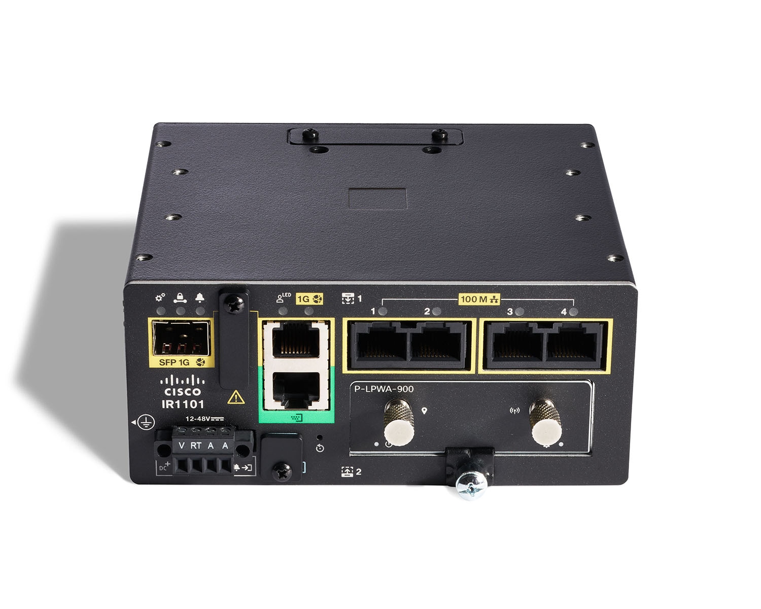
The following figure shows the P-LPWA-900.

Figure 1. P-LPWA-900 LoRaWAN Pluggable Interface Module
LoRaWAN Pluggable Interface Module front face.

The following figure provides details for the Cisco LoRaWAN pluggable module:
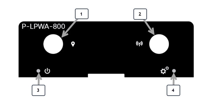
Figure 2. Module Details
LoRaWAN Pluggable Interface Module details, connectors and LEDs
Table 1. Module Details

Item

Description

1

GNSS Connector SMA(f)

2

LoRa RF Connector SMA(f)

3

LoRa Power LED

4

LoRa Status LED

The module dimensions are 2.50” x 0.85” x 3.30” (6.35cm x 2.16cm x 8.38cm). The module weighs 0.4 lbs (181.4 grams).


Note

Additional information can be found in the Cisco LoRa WAN Deployment Guide.

Guidelines and Limitations

The Cisco LoRaWAN pluggable modules have the following guidelines and limitations:

  • Support is available with IOS-XE release 17.10.1 and later

  • Physical OIR is not supported

  • GPS Coordinates locking is mandatory for the latest Common Packet Forwarder (CPF) application to work on the PIM module

The following guidelines and limitations apply to the IR1101:

  • The Cisco LoRaWAN module can be installed in the Base module or Expansion module

  • The Cisco LoRaWAN module is supported in both the IRM-1100-SP and IRM-1100-SPMI expansion modules

  • Only one Cisco LoRaWAN module is supported. Any combination of two or more Cisco LoRaWAN modules is not supported


Important

The Cisco LoRaWAN module can not be used on the IR1101 when running on the npe IOS XE software image.

GPS Channel Plans

GPS check for verification of channel plans is included.


Note

This table is derived from the LoRaWAN Regional Parameters document, version RP2-1.0.2.

Note

The CPF feature is intended to operate only when a GPS fix is actively available or has been stored from an earlier fix. The location derived from the GPS fix must be in one of the countries listed in the table below. If not, the radio will not turn on. This does not apply to Actility LRR since the channel plan is configured on the network server.

Countries supported by GPS check include:

Code

Name

Channel plan

AL

Albania

EU868

AD

Andorra

EU868

AM

Armenia

EU868

AR

Argentina

AU915-928

AT

Austria

EU868

AU

Australia

AU915 (default) AS923

AZ

Azerbaijan

EU868

BY

Belarus

EU868

BE

Belgium

EU868

BA

Bosnia

EU868

BN

Brunei

EU868

BG

Bulgaria

EU868

KH

Cambodia

EU868

CA

Canada

US915 (default) AU915

CN

China

AS923

HR

Croatia

EU868

CY

Cyprus

EU868

CZ

Czech Republic

EU868

DK

Denmark

EU868

EE

Estonia

EU868

FI

Finland

EU868

FR

France

EU868

DE

Germany

EU868

GR

Greece

EU868

HK

Hongkong

EU868

HU

Hungary

EU868

IS

Iceland

EU868

IE

Ireland

EU868

IN

India

IN865

IT

Italy

EU868

JP

Japan

AS923

LA

Laos

EU868

LV

Latvia

EU868

LI

Liechtenstein

EU868

LT

Lithuania

EU868

LU

Luxembourg

EU868

MK

Macedonia

EU868

MY

Malaysia

EU868

MX

Mexico

US915

MD

Moldova

EU868

ME

Montenegro

EU868

NL

Netherlands

EU868

NZ

New Zealand

AS923 AU915

NO

Norway

EU868

PL

Poland

EU868

PT

Portugal

EU868

PR

Puerto Rico

US915

RO

Romania

EU868

RS

Serbia

EU868

SG

Singapore

EU868

SK

Slovakia

EU868

SI

Slovenia

EU868

ZA

South Africa

EU868

ES

Spain

EU868

SE

Sweden

EU868

CH

Switzerland

EU868

TH

Thailand

EU868

TR

Turkey

EU868

GB

United Kingdom

EU868

UA

Ukraine

EU868

US

United States

US915 (default) AU915

VA

Vatican City

EU868

VN

Vietnam

EU868


Note

Refer to the LoRa Alliance Technical Specifications for more information.

Installing the P-LPWA-XXX Pluggable Module

The router may have a blank plate covering the Pluggable Module slot. This will need to be removed prior to installing the P-LPWA-XXX module.

Procedure


Step 1

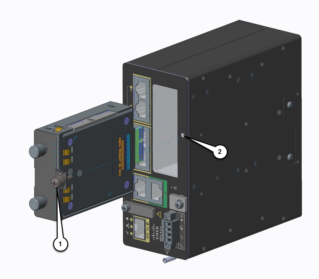
Remove the blank plate by unscrewing the latch lock screw (1 ) that holds the plate secure. Refer to the following figure.

Figure 3. Latch Lock Screw
Blank plate on the router that covers the slot for the pluggable module.

Step 2

Slide the blank plate out of the device.

Step 3

Slide the Pluggable Module into the device as shown in the following figure. The latch lock screw (1 ) aligns with the screw hole (2 ) on the front of the device. Push the Pluggable Module all the way into the device until you feel it seat, and then torque the latch lock screw 8-10 inch-pound (0.9 to 1.1 newton meter).

Figure 4. Pluggable Module Insert
Inserting the Cisco LoRaWAN Pluggable Interface Module into the IR1101 Base.

Step 4

Attach your antennas to the ports on the pluggable module. There are different instructions for each antenna type, be sure to consult the Cisco Industrial Routers and Industrial Wireless Access Points Antenna Guide.

Step 5

If no antennas are being installed on a port, make sure the antenna caps are installed on the connector.


Deployment Scenarios on the IR1101

The IR1101 has two sides that an expansion module can mount to. The top is called the Expansion side, and the bottom is called the Compute side. If the expansion module is connected to the top, then it is referred to as the EM side. If the expansion module is connected on the bottom, then it is referred to as the CM side.


Note

The CM side support will be added in a future release.

Functionality differs depending on which side the expansion module is attached to, how many, and types of expansion modules are in use.

Additional information can be found in the Cisco Catalyst IR1101 Rugged Series Router Software Configuration Guide.

Scenario One

In this scenario, the Cisco LoRaWAN module is installed in the IR1101 Base unit. See the following figure:

In this configuration the Cisco LoRaWAN module has full functionality. The interface numbering in this scenario is LORAWAN 0/1/0.

Scenario Two

In this scenario, the Cisco LoRaWAN module is mounted on the Expansion side, or the top. See the following figure:

In this configuration the LoRaWAN module has full functionality. The interface numbering in this scenario is LORAWAN 0/3/0.

Inventory Details Based on Deployment

The output of the different show commands will show different details based upon which side of the IR1101 base unit it is attached to.

Router# show inventory

+++++++++++++++++++++++++++++++++++++++++++++++++++++++++++++++++++++++
INFO: Please use "show license UDI" to get serial number for licensing.
+++++++++++++++++++++++++++++++++++++++++++++++++++++++++++++++++++++++

NAME: "Chassis", DESCR: "IR1101 Base Chassis"
PID: IR1101-K9         , VID: V03  , SN: FCW2424P05J

NAME: "Module 0 - Mother Board", DESCR: "Cisco IR1101 motherboard"
PID: IR1101-K9         , VID: V03  , SN: FOC24233KEB

NAME: "module subslot 0/0", DESCR: "IR1101-ES-6S"
PID: IR1101-ES-6S      , VID: V01  , SN:

NAME: "module subslot 0/1", DESCR: "P-LTEA-EA Module"
PID: P-LTEA-EA         , VID: V02  , SN: FOC23044M0J

NAME: "Modem on Cellular0/1/0", DESCR: "Sierra Wireless EM7455"
PID: EM7455            , VID: 1.0  , SN: 356129070601460

NAME: "module subslot 0/3", DESCR: "P-LPWA-900 Module"
PID: P-LPWA-900        , VID: V00  , SN: FOC25520G96

NAME: "Module 4 - Expansion Module", DESCR: "IR1100 expansion module with Pluggable slot and SFP"
PID: IRM-1100-SP       , VID: V02  , SN: FCW2544Z0M3
Router#
Router#show platform
Chassis type: IR1101-K9

Slot      Type                State                 Insert time (ago)
--------- ------------------- --------------------- -----------------
0         IR1101-K9           ok                    21:18:40
 0/0      IR1101-ES-6S        ok                    21:17:20
 0/1      P-LTEA-EA           ok                    21:17:20
 0/3      P-LPWA-900          ok                    21:17:20
R0        IR1101-K9           ok, active            21:18:40
F0        IR1101-K9           ok, active            21:18:40
P0        PWR-12V             ok                    21:18:05
Router#
Router#show ip int brief
Interface              IP-Address      OK? Method Status                Protocol
GigabitEthernet0/0/0   172.27.127.211  YES NVRAM  up                    up
FastEthernet0/0/1      unassigned      YES unset  down                  down
FastEthernet0/0/2      unassigned      YES unset  down                  down
FastEthernet0/0/3      unassigned      YES unset  down                  down
FastEthernet0/0/4      unassigned      YES unset  down                  down
GigabitEthernet0/0/5   unassigned      YES unset  down                  down
Cellular0/1/0          unassigned      YES NVRAM  up                    up
Cellular0/1/1          unassigned      YES NVRAM  down                  down
LORAWAN0/3/0           unassigned      YES NVRAM  up                    up
Async0/2/0             unassigned      YES unset  up                    down
Tunnel1                unassigned      YES unset  up                    down
Tunnel11               31.31.31.1      YES NVRAM  up                    up
Tunnel12               30.30.30.1      YES NVRAM  up                    up
VirtualPortGroup0      192.168.2.1     YES NVRAM  up                    up
Vlan1                  unassigned      YES unset  up                    down
Router#

Cisco LoRaWAN Pluggable Interface Module LEDs

There are two LEDs on the front the PIM module. The LED on the left is the Power LED, and the LED on the right is the Status LED.

Figure 5. P-LPWA-xxx LEDs
LoRaWAN Pluggable Interface Module LED descriptions

The following tables describe the LEDs:

LoRa Power LED

Description

Green

Operational with the radio on.

Amber

Module is powering up.

Off

No power.

LoRa Status LED

Description

Green

PIM fully configured. LoRa Interface Operational.

Red

PIM interface error encountered, or a problem occured during configuration.

Off

PIM not fully configured.

The LED status is also available through the CLI.

Router#show led
YSTEM LED : Green

Custom LED : Off

VPN LED : Off

ALARM LED : Off

GigabitEthernet0/0/0 LED : On
FastEthernet0/0/1 LED : Off
FastEthernet0/0/2 LED : Off
FastEthernet0/0/3 LED : Off
FastEthernet0/0/4 LED : Off

LORAWAN0/1/0
Lorawan Module Power LED : GREEN
Lorawan Module Status LED : GREEN
Router#

Supported Antenna and RF Accessories

This section shows details for the supported antennas, cables, and lightning arrestors used in a deployment with the P-LPWA-XXX Pluggable Module.

Table 2. LoRaWAN Antennas

Cisco PID

Connector

Frequency

Peak Gain

Polarization

Radiation Pattern

ANT-LPWA-SMA-D

SMA(m)

863 – 928 MHz

1.0 dBi

Linear, Vertical

Omnidirectional

ANT-LPWA-DB-O-N-5

N(f)

863 – 928 MHz

5.6 dBi

Linear, Vertical

Omnidirectional

ANT-WPAN-OD-OUT-N

N(m)

863 – 928 MHz

1.5 dBi

Linear, Vertical

Omnidirectional

Table 3. GNSS Antennas

Cisco PID

Connector

Frequency

Peak Gain

Polarization

Radiation Pattern

GPS-ACT-ANTM-SMA

SMA(m) with 17 ft. integrated cable.

1575.42 ± 1 MHz

4 dBic

RHCP

Hemispheric

Table 4. Coaxial Cables

Cisco PID

Description

CAB-L240-10-SM-NM

10 ft. LMR-240-DB/FR/CMR, SMA(m)-STR to N(m)-STR

CAB-L400-5-N-N

5 ft. LMR-400-DB, N(m)-STR to N(m)-R/A

CAB-L400-5-N-NS

5 ft. LMR-400-DB, N(m)-STR to N(m)-STR

AIR-CAB010LL-N

10 ft. LMR-400-DB, N(m)-STR to N(m)-STR

CAB-L400-20-N-N

20 ft. LMR-400-DB, N(m)-STR to N(m)-RA

AIR-CAB025HZ-N

25 ft. LMR-400-DB/FR/CMR, N(m)-STR to N(m)-RA

CAB-L600-30-N-N

30 ft. LMR-600-DB, N(m)-STR to N(m)-RA

Table 5. Lightning Arrestors

Cisco PID

Connectors

Description

CGR-LA-NM-NF

N(m)-STR to N(f)-STR

DC to 7 GHz, GDT type, bidirectional

CGR-LA-NF-NF

N(f)-STR to N(f)-STR

DC to 7 GHz, GDT type, bidirectional

For installation instructions and detailed information on any of these antennas, refer to the antenna data sheet on Cisco.com, or see the Cisco Industrial Routers and Industrial Wireless Access Points Antenna Guide.