mSATA SSD Module Installation
Mini-SATA, or mSATA, is a low-profile interface connector that enables more effective Serial ATA (SATA) integration in small form-factor drives roughly the size of a business card, such as solid state disks (SSDs).
This chapter provides an overview of the mSATA SSD available for the Cisco IR829M and IR829B Integrated Services Routers (ISRs). The mSATA SSD provides additional flash memory storage and occupies the mSATA SSD slot in the IR829M/IR829B platform.
Installation Instructions
Note : Ensure that you are using proper static discharge techniques such as a wrist strap and static mat.
Caution : Ensure the device is powered down before performing any removal or installation of a module.
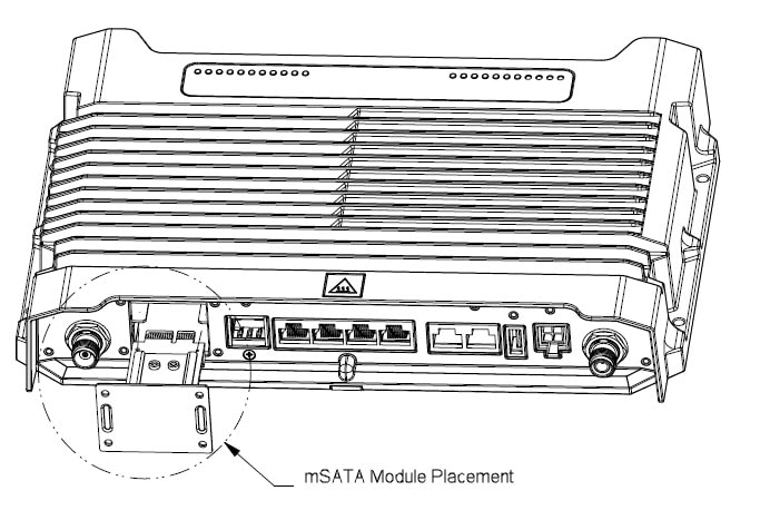
The mSATA SSD module plugs into the slot shown as item number 2 in Cisco IR829 Front Panel Dual Modem

|
1 |
CELLULAR 0 AUX |
5 |
Serial Ports |
|
2 |
mSATA SSD Slot |
6 |
USB 2.0 type-A Port |
|
3 |
Gigabit WAN (SFP) |
7 |
Power Input, Battery, and Ignition connector. Refer to the DC Power section for pin-outs. |
|
4 |
Gigabit Ethernet LAN/PoE (RJ45) |
8 |
WLAN ANT 0 2.4/5.0GHz |
Perform the following steps in order in install the module.
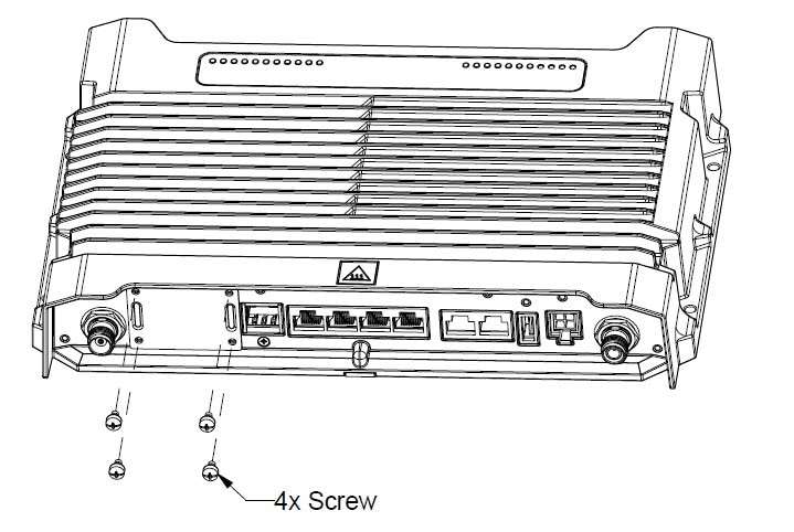
1. Remove the 4 screws holding the cover over the Limited Modularity Slot. If you are replacing an existing module, set them aside for later use to attach the new module. If this is the first time you are installing a module, use the screws provided with the module.
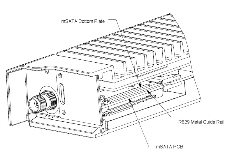
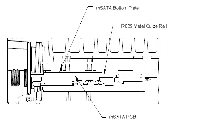
2. Insert the mSATA SSD module into the slot on the IR829. The module slides in with the IR829 metal guide rail in between the mSATA SSD bottom plate and the mSATA SSD PCB.
Refer to Module Placement for the placement of the module.
3. Ensure that the placement of the mSATA SSD module is correct. An incorrect installation can damage the module or the IR829. Refer to the three detailed figures Module Placement (Detail 1), Module Placement (Detail 2), and Module Placement (Detail 3) to assist in proper positioning.

4. After the module is properly inserted, use the 4 screws set aside earlier to tighten the module plate to the IR829. The screws should be torqued to 5-6 in-lb (0.6 N-m). Refer to Securing the New mSATA SSD Module.
5. The installation is now complete. The finished installation is shown in Finished Installation.

 Feedback