5G Sub-6 GHz Pluggable Interface Module

This chapter contains the following sections:

5G Sub-6 GHz Support on IoT Routing

The 5G Sub-6 GHz Pluggable Interface Modules offer 5G capability to the IoT Industrial Router family. The product IDs for the pluggable modules are P-5GS6-GL. The P-5GS6-GL uses the FN980 Telit modem.


Note


  • IOS XE release 17.7.1 is the first software release to provide support for the P-5GS6-GL.


Features and Limitations

The following features and limitations apply across all IoT routing platforms unless specifically mentioned:

  • IoT routing platforms support a maximum of two pluggable modules, with a combination of 5G and 4G PIMs.

  • The pluggable module can be started or stopped through the CLI under exec mode. Also, it can be configured to power off the module to reduce power consumption as needed.

  • The capability to disable FDD Band 30 for vehicular applications is available.

The following are product specific:

  • On the IR1101 with P-5GS6-GL module:

    • When plugged into the base, the module is accessible via Cellular 0/1/0, 0/1/1.

    • The module is not supported on the expansion module.

  • On the IR1101 with the P-5GS6-R16SA module:

    • The module is software and hardware supported on both, base and expansion module.

  • On the IR1800

    • The cellular modems are accessible via Cellular 0/4/0, 0/4/1, 0/5/0, 0/5/1.

5G Pluggable Interface Module Overview

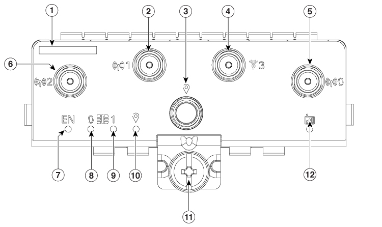
The following figure shows the face plate of P-5GS6-GL pluggable modules:

Figure 1. 5G Pluggable Interface Module - P-5GS6-GL

1

The printed PID

2

Antenna 1 (SMA)

3

GPS (SMA)

4

Antenna 3 (SMA)

5

Antenna 0 (SMA)

6

Antenna 2 (SMA)

7

Enable LED

8

SIM 0 LED

9

SIM 1 LED

10

GPS LED

11

M3.5 thumb-screw

12

Service LED

LED Behaviors

The following table lists the LED indicators and their behavior. The LEDs provide a visual indication of the status and the currently selected services.

LED Indicators:

LED

Color

Function

EN

Green, Yellow

Enable LED

  • Pluggable enable LED

  • Off: System power is off

  • Yellow: Module power is not functioning correctly

  • Green: Module power is on

SIM0

Green, Yellow

SIM0 LED/Activity

  • SIM0 LED status and WWAN activity

  • Off: SIM0 is not installed

  • Yellow: SIM0 is installed, but not active

  • Green: SIM0 installed and active

  • Green Flash: LTE data activity

SIM1

Green, Yellow

SIM1 LED/Activity

  • SIM1 LED status and WWAN activity

  • Off: SIM1 is not installed

  • Yellow: SIM1 is installed, but not active

  • Green: SIM1 installed and active

  • Green Flash: LTE data activity

GPS

Green, Yellow

GPS LED

  • Off: GPS not configured

  • Yellow: Software defined

  • Green: GPS configured

  • Green Flash: GPS acquiring (flashing done by SW)

Service

Green, Yellow, Blue

Service Indication LED

  • Yellow: 3G

  • Green: 4G LTE

  • Blue: 5G

Attaching an Antenna

To attach the antenna in the Pluggable Interface Module, perform the below steps:

Figure 2. Attaching 5G NR Antenna (5G-ANTM-O4-B) to P-5GS6-GL, P-5GS6-R16SA PIM
  1. Attach each SMA cable to the ports as indicated in the table mappings.

  2. Ensure that you tighten and secure each SMA cable into the SMA connector on the PIM.