Overview

The Cisco VG410 Analog Voice Gateway or Cisco VG410 Voice Gateway is a Cisco IOS-XE software-based medium-density analog phone gateway that connects public-switched telephone networks (PSTNs) and existing telephony equipment to Cisco Enterprise Routers.

This voice gateway offers Cisco IOS-XE software manageability on analog phone lines and supports business needs for analog voice ports for modem calls, fax calls, and analog supplementary services.

This device also connects analog phones, fax machines, modems, and speakerphones to the enterprise voice systems and is an intermediate path that enables TDM to IP transition. Further, the fixed-port (FXS and FXO) modules in this voice gateway provide Dual-Tone Multifrequency (DTMF) detection, voice compression and decompression, call progress tone generation, Voice Activity Detection (VAD), echo cancellation, and adaptive jitter buffering.

To know how to install this voice gateway, see the Cisco VG410 Voice Gateway Installation Guide. After installing the voice gateway, use this guide to complete basic router configuration using the setup command facility.


Note


By default, the Cisco VG410 Voice Gateway boots up in the supported Cisco IOS XE platform versions only. To boot the device in a private image release, contact Cisco Technical Assistance Center (TAC).


This document is a summary of the software functionalities that are specific to Cisco VG410 Voice Gateway. This guide also contains information on using the Cisco IOS software to perform other configuration tasks, such as configuring voice ports and other features.

Features and Benefits

Cisco VG410 Voice Gateway provides VoIP connectivity to analog devices such as analog desk phones, analog conference room phones, fax machines, and modems. This voice gateway provides several improvements from the previous high-density analog and digital extension modules (EVMs) in the following ways:

  • Software Digital Signal Processor (DSP): The Cisco VG410 Voice Gateway chassis utilizes its built-in CPU cores to handle the digital signal processing (DSP) tasks required for software implementation. This means that the functionality typically provided by a separate DSP component is now distributed among the CPU cores within the device. Further, the CPU cores effectively handle the necessary DSP operations. The software DSP comes pre-installed as part of the manufacturing process.

  • FXS-E (extended loops or long loops) support: The first 24 ports of all the SKUs on the new modules support FXS-E with:

    • Higher loop current (35 mA) to accommodate specialty phones

    • Longer loop length for loops with 26 AWG wire, up to 11,000 feet (3400 meters)

    • Higher ringing voltage (65 Vrms, no load)

In addition to these features, Cisco VG410 Voice Gateway supports the following features:

  • Webex calling

  • Caller line ID

  • G.711, G.729a, G.729ab, and G.726

  • G722, iLBC

  • Fax pass-through and relay (T.38)

  • Modem pass-through, Modem relay, and V.150.1 MER modem relay support

  • DTMF detection

  • Echo cancellation

  • Voice activity detection

  • Comfort noise generation

  • Real-Time Control Protocol (RTCP)

  • Acoustic shock protection

  • Real-Time Transport Protocol (RTP)

  • RFC 4733 Digit Relay

  • Noise reduction

  • Call Details Records (CDR)

  • Support for Loop-start and Ground start signaling

  • Support for interworking with Cisco Unified Communications Manager (CUCM): Skinny Client Control Protocol (SCCP), Session Initiation Protocol (SIP), and Media Gateway Control Protocol (MGCP) 0.1

  • Cable detection: GR909 line test

FXS Features

The FXS features include:

  • Support for either FXS or DID functionality

  • Message-Waiting Indicator (MWI)

FXO Features

The FXO features include:

  • Overload protection

For more information on features, benefits, and other specifications, refer to the Cisco VG410 Voice Gateway Data Sheet.

Identify the Device

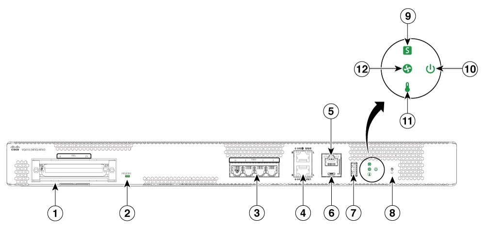
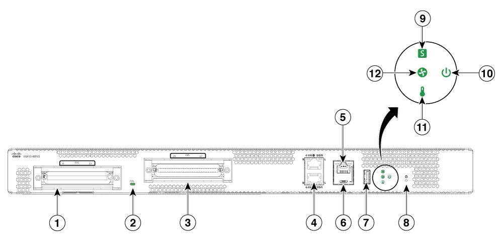
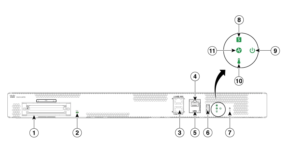
The following images show the I/O panel views of the Cisco VG410 Voice Gateway chassis that help you identify this device:

Figure 1. VG410-24FXS I/O Panel View

1

RJ 21 for FXS port

2

FXS LED

3

2X1 GE port

4

RJ45 console

5

Micro USB console

6

USB 3.0 type A port

7

Reset

8

System status indicator

9

Power supply status indicator

10

Temperature indicator

11

Environmental status indicator

Figure 2. VG410-24FXS/4FXO I/O Panel View

1

RJ 21 for FXS port

2

FXS/FXO LED

3

RJ 11 for FXO port

4

2X1 GE port

5

RJ 45 console

6

Micro USB console

7

USB 3.0 Type A port

8

Reset

9

System status indicator

10

Power Supply status indicator

11

Temperature indicator

12

Environmental status indicator

Figure 3. VG410-48FXS I/O Panel View

1

RJ 21 for FXS port

2

FXS LED

3

RJ 21 for FXS port

4

2X1 GE port

5

RJ45 console

6

Micro USB console

7

USB 3.0 Type A port

8

Reset

9

System status indicator

10

Power status indicator

11

Temperature indicator

12

Environmental status indicator

SKU Information

The following tables specify the Cisco VG410 Voice Gateway SKU information. All the SKUs support the following external interfaces:

Table 1. SKU Information: Front

Front

Details

WAN Port

Two GE RJ-45 copper interface ports support 10BASE-T, 100BASE-TX, and 1000Base-T

Console port

One RJ45 serial console port and one USB console port

Table 2. SKU Information: Back

Back

Details

PSU

Support for one replaceable PSU

Fans

Two or three fixed fans

SKUs

VG410-24FXS

VG410-24FXS/4FXO

VG410-48FXS

FXS Ports

24

24

48

FXO Ports

0

4

0

Number of Failed Over Ports

N/a

4

N/a

Maximum REN

16

16

24

RJ 21 Connectors

1

1

2

Locate the Labels

Use the Cisco Product Identification (CPI) tool to find labels on the platform. The tool provides detailed illustrations and descriptions of where labels are located on Cisco products. It includes the following features:

  • A search option that allows browsing for models by using a tree-structured product hierarchy.

  • A search field on the final results page that makes it easier to look up multiple products.

  • End-of-sale products clearly identified in results lists.

The tool streamlines the process of locating the serial number labels and identifying products. Serial number information expedites the entitlement process and is required to access support services.

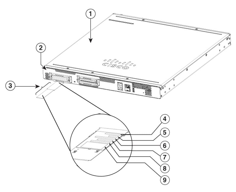
The following image shows the location of the labels on the Cisco VG410 Voice Gateway.
Figure 4. Cisco VG410 Voice Gateway Labels

1

Top Cover

2

PID

3

Label Tray

4

SN

5

CLEI

6

TAN

7

MAC

8

PIDVID

9

QR Code

The Serial number (SN), Common language equipment identifier (CLEI), Top Assembly Number (TAN), Product ID (PID), PID version ID (VID), and Quick response (QR) code are printed on a label at the bottom of the hardware or on a label tray located on the chassis.

LED Information

Table 3. LED Information for Cisco Voice Gateway 400 Series

LED

Colour

Description

PSU

Green/Off

Power Supply Status

Off: The system is powered off.

Yellow: A power supply in the system is not functioning correctly.

Green: The system is operating correctly.

STAT (Status)

Green/Amber/Red

System Status

Yellow Blinking: BIOS/Rommon is booting

Yellow: Rommon has completed booting and system is at Rommon prompt or booting platform software

Green: System is working/operational

USB CON/SERIAL CON

Green

Green: Active console port is USB.

Inactive: No Active console ports on both RJ45 and USB.

Note


When this LED is on, the SER CON LED will be off.

RJ-45 CON

Green/Yellow

Serial Console Active

Green: Indicates that the RJ-45 is the active console port.

No active console ports on both RJ45 and USB.

When this LED is on, the SER CON LED will be off.

TEMP

Green/Yellow/Red

Off: Monitor is not active.

Red: The system has detected a critical overcurrent event and may shut down.

Yellow: One or more temperature sensors in the system are outside the acceptable range.

Green: All the temperature sensors in the system are within acceptable range.

FAN

Yellow/Green/Off

Off: Fans are not being monitored.

Yellow: One or more fans in the system are not functioning.

Green: All the fans are operational.

Ethernet SPD. (Speed of the ethernet port)

Green blinking/Off

Green blinking: Blink frequency indicates port speed:

  • 1 blink+ pause - FE or GE port operating at 10 Mb/s

  • 2 blinks + pause - FE or GE port operating at100 Mb/s

  • 3 blinks + pause - GE port operating at1000 Mb/s

Off: No link or a non-Ethernet 802.3af/t capable device is plugged in.

Ethernet LNK (Link State of the ethernet port)

Green/Off

Green: Ethernet cable is present, and link is established with other side

Off: No link is found

FXS/FXO

(Voice Port Status)

Green/Off

Green: There is at least one active call on the onboard analog FXS/FXO module.

Off: There is no active call on the onboard analog FXS/FXO module.