Traditional edge routing networks
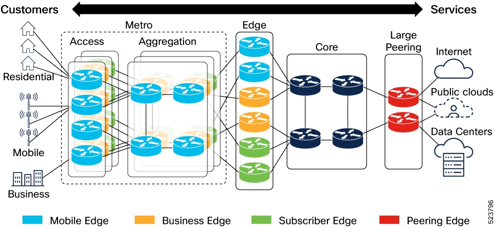
Traditional edge routing network architecture
Traditional Edge routing networks are networks where the edge is a set of dedicated routers placed centrally in the network. Users usually have multiple Edge networks for services such as business VPN (L2 and L3), subscriber services, internet peering, data center interconnect (DCI), cloud gateways, and so on.
Challenges with traditional edge routing networks
Traditional edge routing networks pose challenges in these areas:
-
Distributed services: The bandwidth profile and subscriber density for a distributed edge have changed significantly.
-
Failure Impact: The large radius for failures demands more complex geographically redundant homing. It also necessitates the use of network hardware with redundant processors, fabric cards, line cards, power supplies, ports, and chassis. This increases the cost and complexity.
-
Service optimization: Service providers might have different edge networks for various services. Optimization of these is difficult. The cost of building a solution that meets all the service requirements on a single platform is high. The most demanding services usually set the price for all others.
-
Operational efficiency: Limits operators who want simplicity and efficiency.
-
Platform lock-in: Large systems remain in place for many years thereby slowing down innovation.
-
Upgrades: Upgrades are delayed as much as possible. Forklift upgrades have become a norm due to compatibility challenges between technology generations.
Business challenges
Internet traffic saw a compounded annual growth rate of 30% or higher over the last ten years. Primary challenges for modern networks include proliferation of devices, increase in end-user bandwidth speed, and the continued movement of applications to the cloud.
Traditional edge routing designs face challenges by new traffic and business realities that include
-
ever growing bandwidth with flat average revenue per user (ARPU)
-
increasing cost and complexity of scaling centralized network architectures, and
-
content and application evolution towards distributed network architectures.
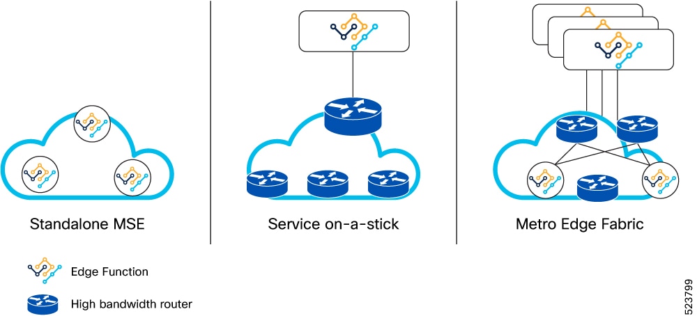
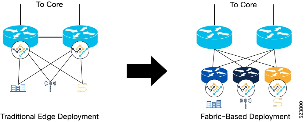
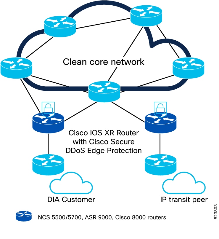
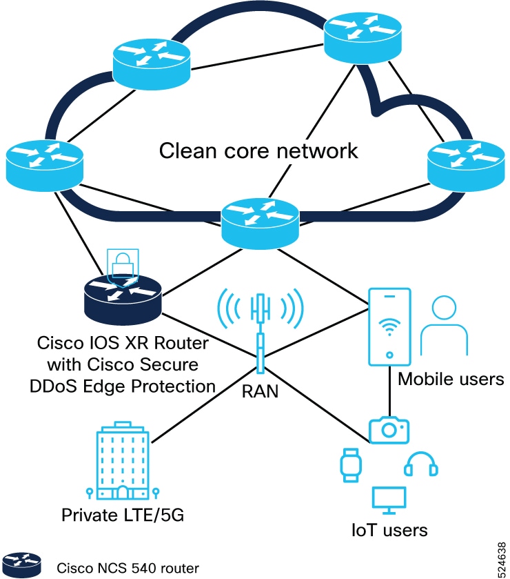
Solution
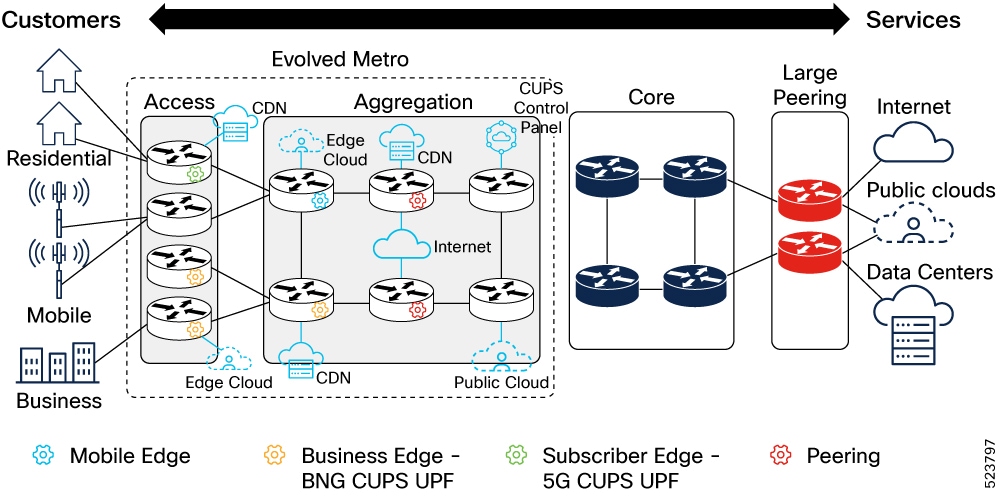
You must build networks to handle the advanced services and increased traffic associated with modern network services. Networks must evolve so the infrastructure layer can keep up with the service layer. The result of these shifts is driving traffic away from centralized delivery to a more distributed network.
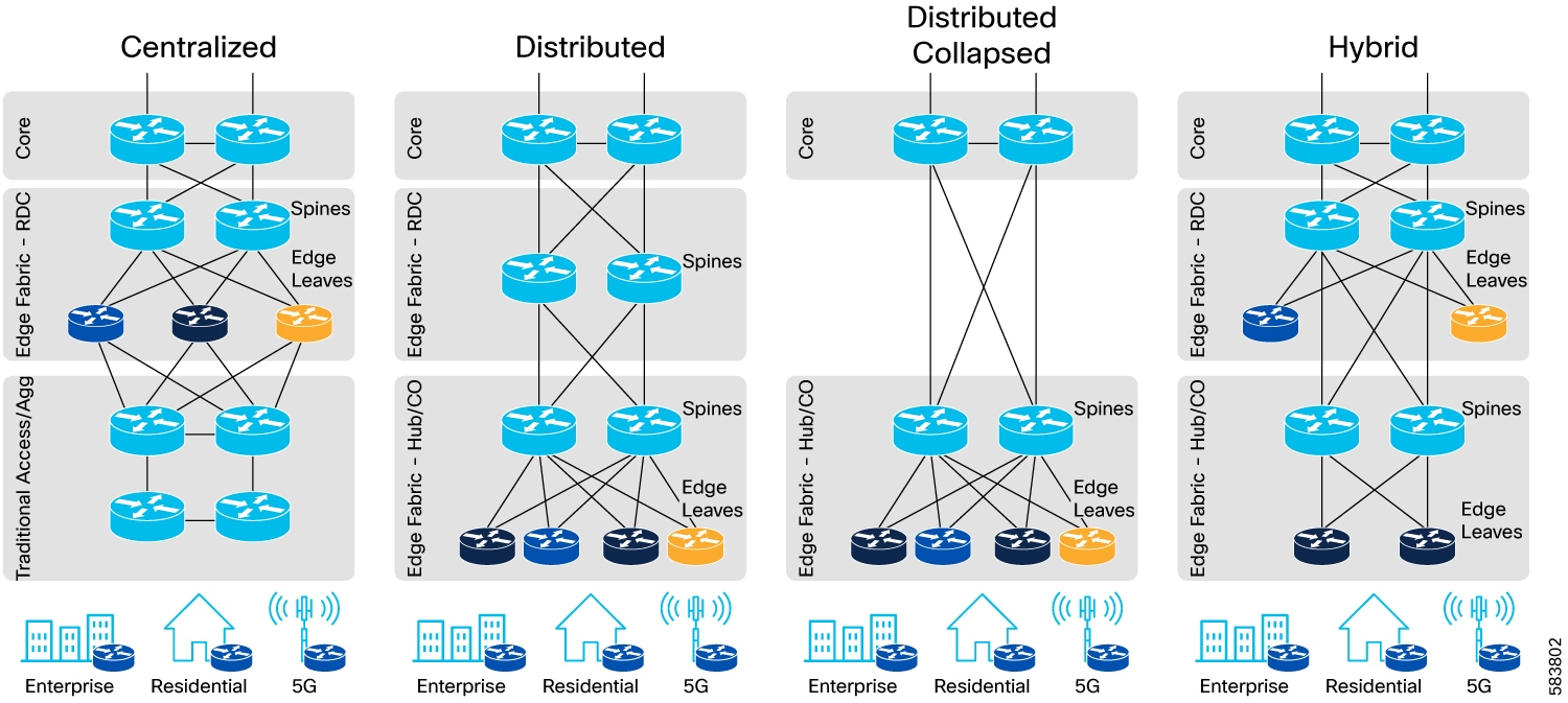
Moving forward, we must consider new network architectures as design options that include these key aspects:
-
Fully distributed and fixed routing systems to deliver services at any place in the network
-
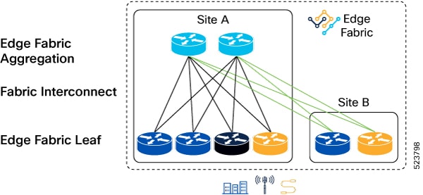
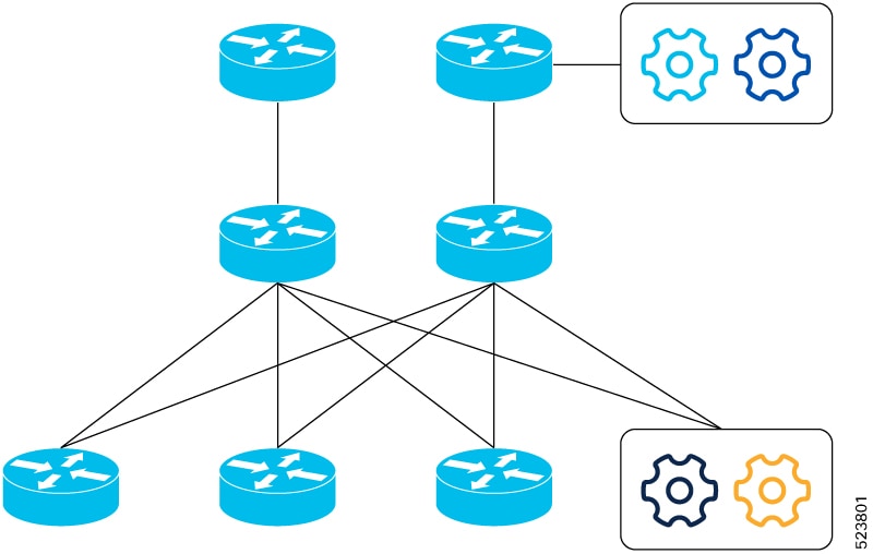
Fabric models delivering scale-out networks that can be built on-demand
-
Flexible deployment options matching provider requirements
-
Network simplification at all layers of the network

 Feedback