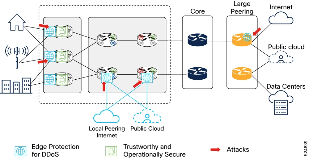
Sample Metro Edge Fabric deployment network
This is a sample topology diagram of Metro Edge Fabric deployment network.
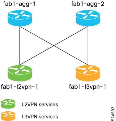
The topology consists of two aggregation routers and two leaf nodes of different role types.
The aggregation routers in the fabric act as inline route reflectors. However, the route reflectors could be located elsewhere.
Control plane configuration
The table lists the protocols and parameters for control plane configuration.
|
Protocol |
Parameters |
|---|---|
| BGP |
ASN 100 IPv4 using separate loopback or route reflector (RR) IPv6 using separate loopback or RR Aggregation routers act as inline RR Aggregation routers have L3VPN and L2VPN address families enabled |
| IS-IS |
Level 2 only SR-MPLS enabled SRv6 enabled TI-LFA enabled |
| Segment Routing |
Flex-Algo 0 Flex-Algo 128 (low latency) |
| IPv4 IP Address Allocations |
10.0.0.0/24 Flex-Algo 0 loopbacks 10.0.128.0/24 Flex-Algo 128 loopbacks |
| SR-MPLS SRGB Allocations |
16000-32000 SRGB 16000-16999 Algo 0 17000-17999 Algo 128 |
| SRv6 IP Address Allocations |
2001:DC::/24 Base SRv6 global block 2001:DC00::/32 Flex-Algo 0 2001:DC80::/32 Flex-Algo 128 |
Additional configuration
The table lists the configuration required for additional elements.
|
Element |
Parameter |
|---|---|
| Route Reflectors |
10.0.0.100 10.0.0.101 |
| SR-PCE |
10.0.0.200 10.0.0.201 |
| SNMP Trap Server |
10.0.0.250 |
Address resource allocation
The table lists the address resource allocation for each node.
|
Node |
IPv4 loopback |
SR-MPLS SIDs |
SRv6 locator |
IPv6 loopback |
|---|---|---|---|---|
| fab1-agg-1 |
10.0.0.1/32 algo 0 10.0.1.1/32 algo 128 |
16001 algo 0 17001 algo 128 |
2001:DC00:0001::/48 algo 0 2001:DC80:0001::/48 algo 128 |
2001:DC00:0001::1/128 |
| fab1-agg-2 |
10.0.0.2/32 algo 0 10.0.1.2/32 algo 128 |
16002 algo 0 17002 algo 128 |
2001:DC00:0002::/48 algo 0 2001:DC80:0002::/48 algo 128 |
2001:DC00:0002::1/128 |
| fab1-l2vpn-1 |
10.0.0.3/32 algo 0 10.0.1.3/32 algo 128 |
16003 algo 0 17003 algo 128 |
2001:DC00:0003::/48 algo 0 2001:DC80:0003::/48 algo 128 |
2001:DC00:0003::1/128 |
| fab1-l3vpn-1 |
105.0.0.4/32 algo 0 105.0.1.4/32 algo 128 10.0.0.4/32 algo 0 10.0.1.4/32 algo 128 |
16004 algo 0 17004 algo 128 |
2001:DC00:0004::/48 algo 0 2001:DC80:0004::/48 algo 128 |
2001:DC00:0004::1/128 |

 Feedback