Cisco ASR 1000 Series Aggregation Services Routers Software Configuration Guide, Cisco IOS XE Gibraltar 16.12.x
Bias-Free Language
The documentation set for this product strives to use bias-free language. For the purposes of this documentation set, bias-free is defined as language that does not imply discrimination based on age, disability, gender, racial identity, ethnic identity, sexual orientation, socioeconomic status, and intersectionality. Exceptions may be present in the documentation due to language that is hardcoded in the user interfaces of the product software, language used based on RFP documentation, or language that is used by a referenced third-party product. Learn more about how Cisco is using Inclusive Language.
This document describes how to configure the UniDirectional Link Detection (UDLD) protocol on the Cisco ASR 1000 Series Aggregation
Services Routers.
Finding Feature Information
Your software release may not support all the features documented in this module. For the latest information about features
and caveats, see the release notes document pertaining to your platform and software release. To find information about the
features documented in this module and to view a list of the releases in which each feature is supported, see the Feature Information for Configuring UDLD on Cisco ASR 1000 Series Aggregation Services Routers.
Use the Cisco Feature Navigator to find information about platform support and Cisco IOS and Cisco Catalyst operating system
software image support. To access the Cisco Feature Navigator, go to
http://www.cisco.com/go/cfn
.
An account on Cisco.com is not required.
Contents
Restrictions for the UDLD Protocol
Currently, the UDLD protocol on the Cisco ASR 1000 Series Aggregation Services Routers has the following limitations:
High Availability (HA) is not supported, but when the Ethernet port is up and UDLD is enabled on the port, the UDLD automatically
performs the detection.
Only Gigabit Ethernet, 10 Gigabit Ethernet, and Fast Ethernet interfaces are supported.
Supports only the basic UDLD functions.
Information About the UDLD Protocol
These sections describe how UDLD works:
UDLD
Overview
The Cisco-proprietary
UDLD protocol allows the devices connected through fiber optic or copper (for
example, Category 5 cabling) Ethernet cables that are connected to the LAN
ports to monitor the physical configuration of the cables and detect whether a
unidirectional link exists. When a unidirectional link is detected, the UDLD
shuts down the affected LAN port and alerts the corresponding user, because
unidirectional links cause a variety of problems, including spanning tree
topology loops.
UDLD is a Layer 2
protocol that works with the Layer 1 protocols to determine the physical status
of a link. In Layer 1, auto negotiation takes care of physical signaling and
fault detection. UDLD performs tasks that auto negotiation cannot perform, such
as detecting the identities of neighbors and shutting down misconnected LAN
ports. When you enable both auto negotiation and UDLD, the Layer 1 and Layer 2
detections work together to prevent physical and logical unidirectional
connections and the malfunctioning of other protocols.
A unidirectional link
occurs whenever the traffic transmitted by a local device over a link is
received by a neighbor, but traffic transmitted from the neighbor is not
received by the local device. If one of the fiber strands in a pair is
disconnected, the link does not stay up as long as the auto negotiation is
active. In such a scenario, the logical link is undetermined, and the UDLD does
not take any action. If both the fibers are working normally in Layer 1, the
UDLD in Layer 2 determines whether those fibers are connected correctly and
whether the traffic is flowing bidirectionally between the correct neighbors.
This check cannot be performed by auto negotiation because auto negotiation
operates in Layer 1.
The Cisco ASR 1000
Series Aggregation Services Routers periodically transmit the UDLD packets to
the neighbor devices on LAN ports where UDLD is enabled. If the packets are
echoed back within a specific timeframe and they are lacking a specific
acknowledgment (echo), the link is flagged as unidirectional and the LAN port
is shut down. Devices on both ends of the link must support UDLD for the
protocol to successfully identify and disable the unidirectional links.
Note
By default, the
UDLD is disabled on all ports to avoid sending unnecessary traffic.
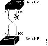
The following figure
shows an example of a unidirectional link condition. Switch B successfully
receives traffic from Switch A on the port. However, Switch A does not receive
traffic from Switch B on the same port. UDLD detects the problem and disables
the port.
Figure 1. Unidirectional
Link
Configuring the UDLD Aggressive Mode
Configure the UDLD aggressive mode only on the point-to-point link between the network devices that support the UDLD aggressive
mode. With UDLD aggressive mode enabled, a port on a bidirectional link that has a UDLD neighbor relationship established
stops receiving the UDLD packets. The UDLD tries to re-establish the connection with the neighbor; the port is disabled after
eight failed retries.
To prevent spanning tree loops, nonaggressive UDLD with the default interval of 15 seconds is fast enough to shut down a unidirectional
link before a blocking port transitions to the forwarding state (with default spanning tree parameters).
When the UDLD aggressive mode is enabled, the UDLD will error disable the ports on the link to prevent the traffic from being
discarded under the following scenarios:
One side of a link has a port (either Tx and Rx) stuck.
One side of a link remains up while the other side of the link has gone down.
Default UDLD
Configuration
The following table
shows the default UDLD configuration.
Table 1. UDLD Default
Configuration
Feature
Default Value
UDLD global
enable state
Globally
disabled
UDLD
aggressive mode
Disabled
UDLD per-port
enable state for fiber-optic media
Disabled
UDLD per-port
enable state for twisted-pair (copper) media
Disabled on
all Ethernet 10/100 and 1000BASE-TX LAN ports
How to Configure the UDLD Protocol
These sections describe how to configure the UDLD protocol:
Enabling UDLD Globally
To globally enable the UDLD on all fiber-optic LAN ports, perform this task:
SUMMARY STEPS
enable
configureterminal
udld {enable | aggressive}
DETAILED STEPS
Command or Action
Purpose
Step 1
enable
Example:
Router# enable
Enables the privileged EXEC mode.
Enter your password, if prompted.
Step 2
configureterminal
Example:
Router# configure terminal
Enters the global configuration mode.
Step 3
udld {enable | aggressive}
Example:
no udld {enable | aggressive}
Example:
Router(config)# udldenable
Enables the UDLD globally on fiber-optic LAN ports.
Note
This command configures only the fiber-optic LAN ports. Individual LAN port configuration overrides the setting of this command.
Use the no form of this command to disable the UDLD globally on fiber-optic LAN ports.
Enabling UDLD on Individual LAN Interfaces
To enable the UDLD on individual LAN interfaces, perform this task:
SUMMARY STEPS
enable
configure terminal
interfacetype slot/port
udldport[aggressive]
DETAILED STEPS
Command or Action
Purpose
Step 1
enable
Example:
Router>enable
EnablestheprivilegedEXECmode.
Enteryourpassword,ifprompted.
Step 2
configure terminal
Example:
Router# configureterminal
Enters the global configuration mode.
Step 3
interfacetype slot/port
Example:
Router(config)# interface gigabitethernet2/2
Selects the LAN port to configure.
Step 4
udldport[aggressive]
Example:
no udld port [aggressive]
Example:
Router(config)# udld port aggressive
Enables UDLD on a specific LAN port. Enter the aggressive keyword to enable the aggressive mode. On a fiber-optic LAN port,
this command overrides the udld enable global configuration command setting.
Use the no form of this command to disable the UDLD on a nonfiber-optic LAN port.
On fiber-optic LAN ports, the no udld port command reverts the LAN port configuration to the udld enable global configuration command setting.
Disabling UDLD on Fiber-Optic LAN Interfaces
To disable the UDLD on individual fiber-optic LAN ports, perform this task:
SUMMARY STEPS
enable
configure terminal
interfacetype slot/port
udldportdisable
DETAILED STEPS
Command or Action
Purpose
Step 1
enable
Example:
Router>enable
EnablestheprivilegedEXECmode.
Enteryourpassword,ifprompted.
Step 2
configure terminal
Example:
Router# configureterminal
Enters the global configuration mode.
Step 3
interfacetype slot/port
Example:
Router(config)# interface gigabitethernet2/2
Selects the LAN port to configure.
Step 4
udldportdisable
Example:
no udld port disable
Example:
Router(config)# udld port disable
Disables UDLD on a fiber-optic LAN port.
Use the no form of this command to revert to the udldenable global configuration command setting.
Note
This command is supported only on the fiber-optic LAN ports.
Configuring the UDLD Probe Message Interval
To configure the time between UDLD probe messages on ports that are in the advertisement mode and are currently determined
to be bidirectional, perform this task:
SUMMARY STEPS
enable
configure terminal
udldmessagetimeinterval
DETAILED STEPS
Command or Action
Purpose
Step 1
enable
Example:
Router>enable
EnablestheprivilegedEXECmode.
Enteryourpassword,ifprompted.
Step 2
configure terminal
Example:
Router# configureterminal
Enters the global configuration mode.
Step 3
udldmessagetimeinterval
Example:
no udld message
Example:
Router(config)# udldmessagetime60
Configures the time between the UDLD probe messages on the ports that are in the advertisement mode and are currently determined
to be bidirectional. Valid values are from 7 to 90 seconds.
Use the no form of this command to return to the default value (15 seconds).
Resetting the Disabled LAN Interfaces Manually
To reset all the LAN ports that have been shut down by UDLD, perform this task:
SUMMARY STEPS
enable
udld reset
DETAILED STEPS
Command or Action
Purpose
Step 1
enable
Example:
Router>enable
EnablestheprivilegedEXECmode.
Enteryourpassword,ifprompted.
Step 2
udld reset
Example:
Router# udld reset
Resets all the LAN ports that have been shut down by UDLD.
Resetting the Disabled LAN Interfaces Automatically
To automatically reset all the LAN ports that have been shut down by UDLD, perform this task:
SUMMARY STEPS
enable
configure terminal
udld recovery
udld recovery interval interval
DETAILED STEPS
Command or Action
Purpose
Step 1
enable
Example:
Router>enable
EnablestheprivilegedEXECmode.
Enteryourpassword,ifprompted.
Step 2
configure terminal
Example:
Router# configureterminal
Enters the global configuration mode.
Step 3
udld recovery
Example:
no udld recovery
Example:
Router(config)# udldrecovery
Enables the recovery timer for the UDLD error disabled state.
Use the no form of this command to disable the recovery timer for the UDLD error disabled state.
Step 4
udld recovery interval interval
Example:
no udld recovery interval
Example:
Router(config)# udldrecoveryinterval100
Specifies the time to recover from a UDLD error disabled state. Valid values are from 30 to 86400 seconds.
Use the no form of this command to return to the default value (300 seconds).
Debugging UDLD
To enable the debugging of an UDLD activity, perform this task:
SUMMARY STEPS
enable
debugudld {events | packets | registries}
DETAILED STEPS
Command or Action
Purpose
Step 1
enable
Example:
Router>enable
EnablestheprivilegedEXECmode.
Enteryourpassword,ifprompted.
Step 2
debugudld {events | packets | registries}
Example:
nodebugudld{events | packets | registries}
Example:
Router#
 debug udld events
Enables the debugging of UDLD process events, packets, or registry events.
Use the no form of this command to disable the debugging of UDLD process events, packets, or registry events.
Configuration Examples for UDLD Protocol
The secion provides the following configuration examples:
The following example show how to use the show command to verify an UDLD configuration:
Sample Output for the show udld interface-id Command
Router# show udld gigabitethernet2/2
Interface Gi2/2
---
Port enable administrative configuration setting: Follows device default
Port enable operational state: Enabled
Current bidirectional state: Bidirectional
Current operational state: Advertisement
Message interval: 60
Time out interval: 5
No multiple neighbors detected

	Entry 1
---
	Expiration time: 146
	Device ID: 1
	Current neighbor state: Bidirectional
	Device name: 0050e2826000
	Port ID: 2/1
	Neighbor echo 1 device: SAD03160954
	Neighbor echo 1 port: Gi1/1
	Message interval: 5
	CDP Device name: 066527791
Example: Verifying Information About Neighbors
The following example shows how to view the information pertaining to neighbors:
Sample Output for the show udld neighbors Command
Router# show udld neighbors
Port     Device Name                    Device ID    Port-ID OperState
-------- ------------------------------ ------------ ------- --------------
Gi3/1    SAL0734K5R2                    1            Gi4/1   Bidirectional
Gi4/1    SAL0734K5R2                    1            Gi3/1   Bidirectional
Example: Displaying all the UDLD Interface Statuses
The follwing example shows how to display all the UDLD interface statuses:
Sample Output for the show udld Command
Router# show udld
Interface Gi0/0/0
---
Port enable administrative configuration setting: Follows device default
Port enable operational state: Disabled
Current bidirectional state: Unknown
Interface Gi0/0/1
---
Port enable administrative configuration setting: Follows device default
Port enable operational state: Disabled
Current bidirectional state: Unknown
Interface Fa0/1/0
---
Port enable administrative configuration setting: Disabled
Port enable operational state: Disabled
Current bidirectional state: Unknown
Interface Fa0/1/1
---
Port enable administrative configuration setting: Disabled
Port enable operational state: Disabled
.
.
.
Additional References
The following sections provide references related to the UniDirectional Link Detection (UDLD) protocol on the Cisco ASR 1000
Series Aggregation Services Routers.
The Cisco Support website provides extensive online resources, including documentation and tools for troubleshooting and resolving
technical issues with Cisco products and technologies.
To receive security and technical information about your products, you can subscribe to various services, such as the Product
Alert Tool (accessed from Field Notices), the Cisco Technical Services Newsletter, and Really Simple Syndication (RSS) Feeds.
Access to most tools on the Cisco Support website requires a Cisco.com user ID and password.
Feature Information
for Configuring UDLD on Cisco ASR 1000 Series Aggregation Services
Routers
The following table
lists the features in this module and provides links to specific configuration
information. Only features that were introduced or modified in Cisco IOS
Release 3.9S or later appear in the table.
Not all commands
may be available in your Cisco IOS software release. For release information
about a specific command, see the corresponding command reference
documentation.
Use the Cisco
Feature Navigator to find information about platform support and software image
support. The Cisco Feature Navigator enables you to determine which Cisco IOS
and Cisco Catalyst operating system software images support a specific software
release, feature set, or platform. To access the Cisco Feature Navigator, go to
http://www.cisco.com/go/cfn
. An account on Cisco.com is not required.
Table 2. Feature
Information for Configuring UDLD on Cisco ASR 1000 Series Aggregation Services
Routers
Feature
Name
Releases
Feature
Information
UniDirectional Link Detection (UDLD) protocol
3.9S
The
Cisco-proprietary UDLD protocol allows devices connected through fiber-optic or
copper (for example, Category 5 cabling) Ethernet cables connected to LAN ports
to monitor the physical configuration of the cables and detect when a
unidirectional link exists. When a unidirectional link is detected, UDLD shuts
down the affected LAN port and alerts users. Unidirectional links can cause a
variety of problems, including spanning tree topology loops.
In Cisco
IOS XE Release 3.9S, this feature was implemented on the Cisco ASR 1000 Series
Aggregation Services Routers.
The
following sections provide information about this feature:

 Feedback