Establishing Subscriber Sessions

A subscriber accesses network resources through a logical connection known as subscriber session. This chapter provides information about various types of subscriber sessions, namely IPoE and PPPoE, and IP addressing by DHCP.

Table 1. Feature History for Establishing Subscriber Sessions

Release

Modification

Release 4.2.0

Initial release

Release 5.3.0

BNG Subscriber Templates feature was introduced.

Release 5.3.2

Support of Parameterized QoS (PQoS) feature for line card subscribers was added.

Release 5.3.1

Support of Geo Redundancy for PPPoE sessions was added.

Release 5.3.3

Option to prevent default ARP entry creation for a subscriber interface was introduced.

Release 6.0.1

IPv6 router advertisements on IPv4 subscriber interface is introduced.

Release 6.1.2

These DHCP enhancements were added:

  • Rich DHCP Option on RADIUS VSA

  • DHCP Options Support for BNG DHCPv6 Proxy Mode

  • DHCP Option 60 Filtering

  • Allow-move for simple IP sessions

  • DHCP Duplicate MAC Session with exclude VLAN option.

Release 6.2.1

These new features were introduced:

  • Configurable DHCPv6 Option 17

  • Unconditional Proxy ARP Response

  • DHCP Soft Pool Migration

  • PPP Class-based DHCPv6 Mode Selection

Release 6.3.1

Introduced the feature, DHCPv6 Link Address Enhancement for PPPoE Session.

Release 6.3.2

Introduced the feature, DHCP L3 Routed Subscriber Snooping.

Release 6.4.1

These new features were introduced:

  • Generic DHCPv4 Options to RADIUS VSA Mapping

  • DHCP Lease From AAA Server

  • AAA Authorization on DHCP RENEW or REBIND

  • DHCPv6 Lease Time for Class Profile

  • Rich DHCPv6 Option on RADIUS VSA for DHCPv6 Servers

  • DHCP IPv6 Lease from the AAA Server

  • DHCPv6 Option 1 and Option 16 to Form Authentication Username

  • DHCPv6 Option 16 Filtering

Release 6.4.2

Introduced the BNG PPPoE LAC support for LC subscribers.

Release 7.3.1

Addded BNG support on Cisco ASR 9000 5th Generation line cards.

Release 7.3.2

Addded BNG support on Cisco ASR 9000 5th Generation line cards for the following features:

  • BNG over PWHE access

  • PPPoE LAC subscribers

  • PPPoE keepalive offload

This chapter covers these topics:

Subscriber Session Overview

A session represents the logical connection between the customer premise equipment (CPE) and the network resource. To enable a subscriber access the network resources, the network has to establish a session with the subscriber. Each session establishment comprises of these phases:


Note


When packets arrive on an access interface, an attempt is made to link that packet to a subscriber context.

  • For PPPoE sessions the Source MAC of the CPE, Access interface and PPPoE Session ID are used to match the remote peer to a subscriber interface.

  • For IPoE sessions the Source MAC, Access interface and IP address are verified against the DHCP binding to find a matching subscriber interface.

If there is no match, the packet is mapped against the access (sub-)interface. Considering that the access interface in IPoE designs is IP enabled (eg via an IP-Unnumbered configuration) that packets are processed like regular IP. In order to secure your BNG access interface, you will want to apply either uRPF or an Access-List blocking everything but DHCP incoming on the access interface to limit remote subscribers for which we don't have an interface created from accessing network resources.


  • Establishing a connection—in this phase CPE finds the BNG with which to communicate.

  • Authenticating and authorizing the subscriber—in this phase, BNG authenticates the subscribers and authorizes them to use the network. This phase is performed with the help of the RADIUS server.

  • Giving subscriber an identity—in this phase, the subscriber is assigned an identity, the IP address.

  • Monitoring the session—in this phase, BNG ascertains that the session is up and running.

The subscribers are not configured directly on BNG. Instead, a framework is created on which subscriber features and subscriber sessions are started and stopped dynamically. The framework consists of control policies and dynamic templates, which perform these functions:

  • Control policy determines the action BNG takes when specific events, such as receipt of a session start request, or failure of authentication, occurs. The action is determined by the class-map defined in the control policy. The action involves activating dynamic templates.

  • Dynamic template contains a set of CLI commands that are applied to a subscriber session. Multiple dynamic templates can be activated, one at a time, on the same subscriber interface. Also, the same dynamic template can be activated on multiple subscriber interfaces through different control policies.

Service providers can deploy subscribers over VLAN in these ways:

  • 1:1 VLAN model—This model depicts a scenario where one dedicated VLAN is available for each customer. Each VLAN is an q-in-q VLAN where the inner VLAN tag represents the subscriber and the outer VLAN tag represents the DSLAM.

  • N:1 VLAN model—This model depicts a scenario where multiple subscribers are available on a shared VLAN. The VLAN tags represent the DSLAM or the aggregation device.

  • Ambiguous VLANs —This model allows the operator to specify a large number of VLANs in a single CLI line. Using ambiguous VLAN, a range of inner or outer tags (or both) can be configured on a VLAN sub-interface. This is particularly useful for the 1:1 model, where every subscriber has a unique value for the set of VLAN tags. For more information about ambiguous VLANs, see Subscriber Session on Ambiguous VLANs.

The subscriber sessions are established over the subscriber interfaces, which are virtual interfaces. It is possible to create only one interface for each subscriber session. A port can contain multiple VLANs, each of which can support multiple subscribers. BNG creates subscriber interfaces for each kind of session. These interfaces are named based on the parent interface, such as bundle-ether 2.100.pppoe312. The subscribers on bundles (or bundle-VLANs) interfaces allow redundancy, and are managed on the BNG route processor (RP).

For details on subscriber session limit, see Subscriber Session Limit.

To provide network redundancy and load balancing, the service provider can deploy multiple links between the DSLAM and the BNG. The individual links can be grouped into ether-bundles, including VLANs over ether-bundles, or link aggregation groups (LAGs). The subscriber sessions can be active on any link within the bundle or group. If a BNG is deployed in a LAG configuration, all traffic for one subscriber should be configured to traverse one link of the ether-bundle. Load-balancing is achieved by putting different subscribers on different links.

There are two mechanisms to establish a subscriber session, namely, IPoE and PPPoE. These are discussed next in the next topics.

Line card (LC) subscribers are supported in BNG. For details, see Line Card Subscribers.

BNG supports interface based static sessions, where all traffic belonging to a particular VLAN sub-interface is treated as a single session. For details, see Static Sessions.


Note


  • If a clear subscriber session all command is issued with the intend to clear all the subscriber sessions and if a route processor fail over (RPFO) occurs while the session bring down is in progress, then it is recommended to re-run the same command post RPFO, to ensure all the remaining sessions, if any, are brought down.

  • Do not add or delete any Virtual Routing and Forwarding (VRF) configuration when the subscriber sessions are being brought up or brought down. Otherwise, there can be issues while creating new subscriber sessions that can lead to system instability.

  • With packet-triggered session initiator configured, new sessions (for subscriber session with already activated state or subscriber sessions which are duplicating the credentials of already activated subscribers) are attempted even before clearing the previous session. This happens while clearing a subscriber session (either using CoA or using clear subscriber session command) when the user is sending traffic. From Cisco IOS XR Software Release 5.2.2 and later, if a packet-triggered session gets to an error state (Access-Reject or feature programming error) during session establishment procedure, then a penalty of two minutes is applied to that subscriber. That is, BNG does not accept a new session from the same subscriber for a time period of two minutes. This avoids hogging of system resources by a DoS attack. The penalty remains the same if the session was cleared either using CoA or using clear subscriber session command. For IP-initiated sessions, the subscribers can disconnect either based on the idle timeout or based on the portal logout. For idle timeout scenario, the penalty does not have any impact, because the penalty is applicable only if the subscriber sends traffic while the session is being cleared. In a portal logout scenario, a CoA is triggered by the portal. If subscriber sends traffic when the CoA is received, then the two-minute penalty is applied to that subscriber; else there is no penalty.

    From Cisco IOS XR Software Release 5.3.0 and later, the penalty is reduced to 10 seconds only for scenarios where the previous session of the same subscriber is in disconnecting state. For other scenarios, the penalty remains as two minutes.


Restrictions

  • If the subscriber's VRF is taken from the access interface's VRF value, then the VRF, configured in the dynamic template used by the subscriber, must match. If the two VRFs do not match, then the session would not work properly.

  • ACL logging on BNG dynamic template is not supported.

  • The BNG supports various features associated with BNG subscriber sessions and are linked to a BNG subscriber session during the initiation of the session or through a Change of Authorization (CoA). These features include:

    • Dynamic templates for IP subscribers and PPP services.

    • Policies and access list bindings related to subscriber access interfaces.

    • Quality of Service and Policy-Based Routing configurations, such as class maps and policy maps.

    • Access Control Lists (ACLs) and Access Control Entries (ACEs).

    • DHCP profiles and their bindings to interfaces.

    The BNG does not support modifications to these features during active BNG sessions. Any changes made during active BNG sessions may negatively impact the functionality and result in unpredictable behavior.

    We recommend you avoid any actions such as enabling, disabling, or modifying these features while they are active in a subscriber session.

Establishing IPoE Session

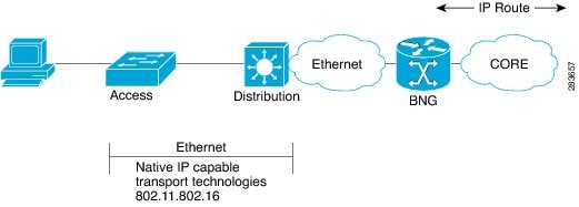
In an IPoE subscriber session, subscribers run IPv4 or IPv6 on the CPE device and connect to the BNG through a Layer-2 aggregation or Layer-3 routed network. IP subscriber sessions that connect through a Layer-2 aggregation network are called L2-connected and sessions that connect through routed access network are called L3-connected or routed subscriber sessions. IPoE subscriber sessions are always terminated on BNG and then routed into the service provider network. IPoE relies on DHCP to assign IP address. A typical IPoE session is depicted in the following figure.

Figure 1. IPoE Session


The process of provisioning an IPoE session involves:

For details on routed subscriber sessions, see Routed Subscriber Sessions.

BNG supports IPoE subscriber session-restart. For details, see Subscriber Session-Restart.

Configuring the ipoe-dhcp-client-reboot command under the subscriber mode brings down a subscriber session when IPv4 DHCP discover or IPv6 DHCP Solicit packet are received for an existing IPv4 or IPv6 subscriber session.

To limit the default ARP entry creations, see Prevent Default ARP Entry Creation for a Subscriber Interface.


Note


If an access interface in BNG is configured to support only packet (PKT) triggered sessions, or both DHCP and PKT triggered sessions, then a burst of traffic with unique flows can affect the BNG router in terms of processing each packet to determine if it is an IPoE (PKT triggered) packet. New subscriber sessions cannot be established in these scenarios and this can in turn lead to system instability. Therefore, it is mandatory to configure static lpts policer for unclassified rsp protocol, on each of the line cards (LCs), such that the traffic rate does not exceed 150 pps per LC. The rate configured is applied at network processor (NP). Therefore, for an LC with 4 NPs, the rate should be configured as 38 (150/4), to achieve a traffic rate of 150 pps. For example, lpts punt police location 0/RSP0/CPU0 protocol unclassified rsp rate 38.

Restrictions

Enabling IPoE subscribers on an access-interface is subjected to a restriction that packet-triggered L2 sessions (initiator unclassified-source ) are not supported for IPv6.

Enabling IPv4 or IPv6 on an Access Interface

Perform these tasks to enable IPv4 and IPv6 processing on an access interface. In this example, the IPv4 is being provisioned on an unnumbered bundle-interface.

SUMMARY STEPS

  1. configure
  2. interface type interface-path-id
  3. arp learning disable
  4. ipv4 unnumbered interface-type interface-instance
  5. ipv6 enable
  6. Use the commit or end command.

DETAILED STEPS

  Command or Action Purpose

Step 1

configure

Example:


RP/0/RSP0/CPU0:router# configure

Enters global configuration mode.

Step 2

interface type interface-path-id

Example:


RP/0/RSP0/CPU0:router(config)# interface Bundle-Ether100.10

Enters interface configuration mode for the bundle-interface.

Step 3

arp learning disable

Example:


RP/0/RSP0/CPU0:router(config-if)# arp learning disable

Disables arp learning for the access-interface.

Step 4

ipv4 unnumbered interface-type interface-instance

Example:


RP/0/RSP0/CPU0:router(config-if)# ipv4 unnumbered loopback 5

Enables IPv4 processing on a unnumbered interface without assigning an explicit IPv4 address to that interface. Instead, the IP address is borrowed from the loopback interface. For the "ipv4 unnumbered" command, you must specify another interface in the same router that has been assigned an IP address and whose status is displayed as “up” for the show interfaces command.

Step 5

ipv6 enable

Example:


RP/0/RSP0/CPU0:router(config-if)# ipv6 enable

Enables IPv6 processing on an unnumbered interface that has not been assigned an explicit IPv6 address.

Note


This step not only enables IPv6 processing on the interface, but also assigns an IPv6 link-local unicast address to it.

Step 6

Use the commit or end command.

commit —Saves the configuration changes and remains within the configuration session.

end —Prompts user to take one of these actions:
  • Yes — Saves configuration changes and exits the configuration session.

  • No —Exits the configuration session without committing the configuration changes.

  • Cancel —Remains in the configuration session, without committing the configuration changes.

Enabling IPv4 or IPv6on an Access Interface: Examples


//Enabling IPv4 on an Access Interface

configure
interface Bundle-Ether100.10
arp learning disable
ipv4 unnumbered loopback 5
!
!
end


//Enabling IPv6 on an Access Interface

configure
interface Bundle-Ether100.10
arp learning disable
ipv6 enable
!
!
end

Creating Dynamic Template for IPv4 or IPv6 Subscriber Session

Perform this task to create a dynamic template for IPv4 or IPv6 subscriber session. As an example, in this dynamic template you will specify the MTU value for the IPv4 or IPv6 session and enable uRPF. The uRPF ensures that the traffic from malformed or forged IPv4 source addresses are not accepted on the subscriber interface. For more information about uRPF feature, see uRPF.

SUMMARY STEPS

  1. configure
  2. dynamic-template
  3. type { ipsubscriber | ppp | service } dynamic-template-name
  4. timeout idle value [threshold duration] [traffic {both | inbound | outbound}]
  5. accounting aaa list default type session periodic-interval value dual-stack-delay value
  6. {ipv4 | ipv6} mtu mtu-bytes
  7. {ipv4 | ipv6}verify unicast source reachable-via rx
  8. Use the commit or end command.

DETAILED STEPS

  Command or Action Purpose

Step 1

configure

Example:


RP/0/RSP0/CPU0:router# configure

Enters global configuration mode.

Step 2

dynamic-template

Example:


RP/0/RSP0/CPU0:router(config)# dynamic-template

Enters the dynamic-template configuration mode.

Step 3

type { ipsubscriber | ppp | service } dynamic-template-name

Example:


RP/0/RSP0/CPU0:router(config-dynamic-template)# type ipsubscriber ipsub1

Creates a dynamic-template with an user-defined name for IP subscriber.

Step 4

timeout idle value [threshold duration] [traffic {both | inbound | outbound}]

Example:


RP/0/RSP0/CPU0:router(config-dynamic-template-type)# timeout idle 600 threshold 2 traffic both

IPv4 or IPv6 or Dual-stack Subscribers support idle timeout feature.

Note


You can configure a monitor action under the idle timeout event for a subscriber policy, to prevent the termination of subscriber sessions when the idle timeout period expires.

Step 5

accounting aaa list default type session periodic-interval value dual-stack-delay value

Example:


RP/0/RSP0/CPU0:router(config-dynamic-template)# accounting aaa list default type session periodic-interval 60 dual-stack-delay 1

Configures the subscriber accounting feature.

Step 6

{ipv4 | ipv6} mtu mtu-bytes

Example:


RP/0/RSP0/CPU0:router(config-dynamic-template-type)# ipv4 mtu 678

RP/0/RSP0/CPU0:router(config-dynamic-template-type)# ipv6 mtu 548

Sets IPv4 or IPv6 maximum transmission unit (MTU). The range is from 68 to 65535 bytes. The MTU value defines the largest packet size that can be transmitted during the subscriber session.

Step 7

{ipv4 | ipv6}verify unicast source reachable-via rx

Example:


RP/0/RSP0/CPU0:router(config-dynamic-template-type)# ipv4 verify unicast source reachable-via rx

RP/0/RSP0/CPU0:router(config-dynamic-template-type)# ipv6 verify unicast source reachable-via rx

Enables uRPF for packet validation that performs source address reachability check.

Step 8

Use the commit or end command.

commit —Saves the configuration changes and remains within the configuration session.

end —Prompts user to take one of these actions:
  • Yes — Saves configuration changes and exits the configuration session.

  • No —Exits the configuration session without committing the configuration changes.

  • Cancel —Remains in the configuration session, without committing the configuration changes.

Creating Dynamic Template for IPv4 or IPv6 Subscriber Session: Examples


//Creating Dynamic Template for IPv4 Subscriber Session

configure
dynamic-template
type ipsubscriber ipsub1
timeout idle 600
accounting aaa list default type session periodic-interval 60 dual-stack-delay 1
ipv4 mtu 678
ipv4 verify unicast source reachable-via rx
!
!
end

//Creating Dynamic Template for IPv6 Subscriber Session

configure
dynamic-template
type ipsubscriber ipsub1
timeout idle 600 threshold 2 traffic both
accounting aaa list default type session periodic-interval 60 dual-stack-delay 1
ipv6 mtu 678
ipv6 verify unicast source reachable-via rx
!
!
end

Creating a Policy-Map to Run During IPoE Session

Perform this task to create a policy-map that will activate a predefined dynamic-template during an IPoE subscriber session. As an example, this policy-map activates a dynamic template, and applies a locally defined authorization setting, during a session-start event.

SUMMARY STEPS

  1. configure
  2. policy-map type control subscriber policy_name
  3. event session-start match-first
  4. class type control subscriber class_name do-until-failure
  5. sequence_number activate dynamic-template dynamic-template_name
  6. sequence_number authorize aaa list default format format_name password password
  7. Use the commit or end command.

DETAILED STEPS

  Command or Action Purpose

Step 1

configure

Example:


RP/0/RSP0/CPU0:router# configure

Enters global configuration mode.

Step 2

policy-map type control subscriber policy_name

Example:


RP/0/RSP0/CPU0:router(config)# policy-map type control subscriber IPoE_policy

Creates a new policy map of the type "control subscriber" with the name "IPoE_policy".

Step 3

event session-start match-first

Example:


RP/0/RSP0/CPU0:router(config-pmap)# event session-start match-first

Defines an event (session start) for which actions will be performed.

Step 4

class type control subscriber class_name do-until-failure

Example:


RP/0/RSP0/CPU0:router(config-pmap-e)# class type control subscriber class-default do-until-failure

Configures the class to which the subscriber has to be matched. When there is a match, executes all actions until a failure is encountered.

Step 5

sequence_number activate dynamic-template dynamic-template_name

Example:


RP/0/RSP0/CPU0:router(config-pmap-c)# 1 activate dynamic-template ipsub1

Allows authentication of the subscriber to be triggered using the complete structure username.

Step 6

sequence_number authorize aaa list default format format_name password password

Example:


RP/0/RSP0/CPU0:router(config-pmap-c)# 1 authorize aaa list default format RM_User password Cisco

Allows authorization of the subscriber to be triggered using the domain name of the subscriber. Also, provides domain format-rule, which helps to parse the domain from a complete structured username.

Step 7

Use the commit or end command.

commit —Saves the configuration changes and remains within the configuration session.

end —Prompts user to take one of these actions:
  • Yes — Saves configuration changes and exits the configuration session.

  • No —Exits the configuration session without committing the configuration changes.

  • Cancel —Remains in the configuration session, without committing the configuration changes.

Creating a Policy-Map to Run During IPoE Session: An example


configure
policy-map type control subscriber IPoE_policy
event session-start match-first
class type control subscriber class-default do-until-failure
1 activate dynamic-template ipsub1
1 authorize aaa list default format RM_User password Cisco
!
!
end

Enabling IPoE Subscribers on an Access Interface

Perform this task to enable IPoE subscriber creation on an access interface.

SUMMARY STEPS

  1. configure
  2. interface interface-type interface-path-id
  3. arp learning disable
  4. {ipv4 | ipv6} address {ipv4_address | ipv6_address} ipsubnet_mask
  5. service-policy type control subscriber policy-name
  6. encapsulation dot1q value
  7. ipsubscriber {ipv4 | ipv6}l2-connected
  8. initiator dhcp
  9. initiator unclassified-source [address-unique]
  10. Use the commit or end command.

DETAILED STEPS

  Command or Action Purpose

Step 1

configure

Example:


RP/0/RSP0/CPU0:router# configure

Enters global configuration mode.

Step 2

interface interface-type interface-path-id

Example:

RP/0/RSP0/CPU0:router(config)# interface Bundler-Ether400.12

Configures an interface and enters interface configuration mode.

  • The type argument specifies an interface type. For more information on interface types, use the question mark (?) online help function.
  • The instance argument specifies either a physical interface instance or a virtual instance.
    • The naming notation for a physical interface instance is rack/slot/module/port. The slash (/) between values is required as part of the notation.
    • The number range for a virtual interface instance varies depending on the interface type.

Step 3

arp learning disable

Example:


RP/0/RSP0/CPU0:router(config-if)# arp learning disable

Disables arp learning for the access-interface.

Step 4

{ipv4 | ipv6} address {ipv4_address | ipv6_address} ipsubnet_mask

Example:

RP/0/RSP0/CPU0:router(config-subif)# ipv4 address 3.5.1.1 255.255.0.0
or

Example:

RP/0/RSP0/CPU0:router(config-subif)# ipv6 address 1144:11

Sets the IPv4 address or an IPv6 address for an interface.

Step 5

service-policy type control subscriber policy-name

Example:

RP/0/RSP0/CPU0:router(config-subif)# service-policy type control subscriber PL4

Associates a subscriber control service policy to the interface.

Note


Refer to the "Configuring a Subscriber Policy Map" procedure to create a PL4 policy-map.

Step 6

encapsulation dot1q value

Example:

RP/0/RSP0/CPU0:router(config-subif)# encapsulation dot1q 40

Defines the matching criteria to map 802.1Q frames ingress on an interface to the appropriate service instance. The value ranges from 1 to 4094.

Step 7

ipsubscriber {ipv4 | ipv6}l2-connected

Example:

RP/0/RSP0/CPU0:router(config-subif)# ipsubscriber ipv4 l2-connected
or

Example:

RP/0/RSP0/CPU0:router(config-subif)# ipsubscriber ipv6 l2-connected

Enables creations of L2-connected IPv4 or IPv6 subscribers on the sub-interface.

Note

 
It is not recommended to remove these call flow-initiated configurations, after subscriber sessions are active:
  • For an IPoE subscriber session, you must not delete the ipsubscriber ipv4 l2-connected initiator dhcp command from the sub-interface

  • For a packet-triggered subscriber session, you must not delete the ipsubscriber ipv4 l2-connected initiator unclassified-source command from the sub-interface.

Step 8

initiator dhcp

Example:

RP/0/RSP0/CPU0:router(config-subif-ipsub-ipv4-l2conn)# initiator dhcp
or

Example:

RP/0/RSP0/CPU0:router(config-subif-ipsub-ipv6-l2conn)# initiator dhcp

Configures DHCP as the first-sign-of-life (FSOL) protocol for IP subscriber.

Step 9

initiator unclassified-source [address-unique]

Example:

RP/0/RSP0/CPU0:router(config-subif-ipsub-ipv4-l2conn)# initiator unclassified-source

Configures unclassified packets as the first-sign-of-life (FSOL) for IPv4 subscriber.

The address-unique option enables subscriber IP uniqueness check during FSOL processing, thereby preventing invalid sessions from creating interfaces. This option is available from Cisco IOS XR Software Release 5.2.2 and later.

Note

 
  • The initiator unclassified-source option is not supported for IPv6.

  • If multiple initiators are used, use a policy or class map to prevent overlap of the IP addresses for the different sources.

Step 10

Use the commit or end command.

commit —Saves the configuration changes and remains within the configuration session.

end —Prompts user to take one of these actions:
  • Yes — Saves configuration changes and exits the configuration session.

  • No —Exits the configuration session without committing the configuration changes.

  • Cancel —Remains in the configuration session, without committing the configuration changes.

Enabling IPoE Subscribers on an Access Interface: Examples


configure
interface Bundler-Ether400.12
arp learning disable
ipv4 address 3.5.1.1 255.255.0.0
service-policy type control subscriber PL4
encapsulation dot1q 40
ipsubscriber ipv4 l2-connected
initiator dhcp
initiator unclassified-source
!
!
end

configure
interface Bundler-Ether400.12
arp learning disable
ipv6 address 4444:34
service-policy type control subscriber PL4
encapsulation dot1q 40
ipsubscriber ipv6 l2-connected
initiator dhcp
!
!
end

Routed Subscriber Sessions

BNG supports L3 or routed subscriber sessions (DHCP-initiated and Packet-triggered), where IP subscribers are connected through a routed access network. The policies and services on the routed subscriber sessions are applied in a similar manner as with L2 subscriber sessions.

This figure shows a typical routed subscriber session network model:
Figure 2. Routed Subscriber Session Network Model


L2-connected subscribers are either directly attached to the physical interfaces of BNG or connected to BNG through a Layer 2 access network, such as a bridged or a switched network. Each user device here is a unique subscriber session. In case there is a routed CPE, the CPE owns the subscriber session on the BNG, and all devices behind the CPE performs NAT. The CPE holds the start of the session to BNG. The subscriber is keyed on the MAC address. Because there is a switched network, the BNG directly sees the MAC address of the device.

This figure shows a typical L2-connected subscriber session:
Figure 3. L2-connected Subscriber Session


Whereas, routed subscribers are connected to BNG through routed device(s). The devices behind the CPE's MAC address are not visible to BNG. The subscriber is no longer keyed on MAC address. Instead, ip-address is used to key the subscriber session of the device.

In a typical L3 routed aggregation model, the CPE uses NAT to cover up the devices behind the routed CPE. The BNG sees a subscriber session that is initiated and linked to the WAN interface of the routed CPE.

With this routed subscriber session functionality, you can connect devices and create subscriber sessions that are behind a routed CPE.

This figure shows a typical routed subscriber session:
Figure 4. Routed Subscriber Session


To configure an access-interface to host routed subscriber sessions, see Configuring Routed Subscriber Sessions.

Routed subscriber sessions come up only if a summary route is added on BNG. The summary route can be either statically configured, or created through some of the routing protocols like OSPF or EIGRP. The summary route VRF must be same as the access-interface VRF in BNG. Modifying or deleting a summary route that is pointing to the subscriber access-interface, while the subscriber sessions are active, may cause a minimal traffic disruption due to route re-convergence. Therefore, it is recommended that the summary route pointing to the subscriber access-interface be modified or deleted only after deleting the sessions that are using that static summary route.

DHCP-initiated Routed Subscriber Sessions

BNG supports DHCPv4-initiated routed subscriber sessions.

DHCP Interaction

The DHCP pool IP address range in BNG must be in compliance with the summary route address range. This DHCP pool IP address range must also match the IP address subnet of the first hop router, which acts as the DHCP relay or proxy. The route for this particular address range must be configured in BNG, so that BNG can reach the subnet of the first hop router, and eventually reach the subscriber.

The subscriber route need not be explicitly added. It is added internally by the BNG process, when the subscriber session is up.

For routed subscriber sessions, the DHCP server should be configured locally on ASR9K router itself, or a DHCP radius proxy should be used. Proxy mode to an external DHCP server is not supported. For details on the call flow of a DHCPv4-initiated session, see Call Flow of DHCPv4-initiated Routed Subscriber Sessions.

Session Initiator and Session Identifier

Routed sessions should use IP-based session in-band initiator; whereas L2 connected sessions can have unclassified-mac as session in-band initiator. Only DHCPv4 initiated sessions are supported.

Access Interface Features

Although features like ACL and Netflow may be configured on the access-interface, they do not get applied on the subscriber traffic under the respective access-interface. Which features get applied on the subscriber interface is decided based on the dynamic-template configurations under the interface or through RADIUS profile.

VRF Mapping

Routed subscriber sessions support VRF mapping, which allows subscriber to be in a different VRF other than the access-interface VRF. The DHCP pool VRF in BNG must be same as the subscriber VRF, whereas the summary route VRF must be same as the access-interface VRF in BNG. During subscriber creation, information from the dynamic-template or RADIUS is used to set the subscriber VRF. Because access-interface is not used to classify subscriber traffic, the IP address given to subscriber in a given access-interface must be a non-overlapping address.

Non-Subscriber Traffic

Because DHCP is the only session initiator for a routed subscriber, a non-subscriber packet is routed as a normal packet on an access-interface. For such packets, the features on access interface are applicable as normal. To prevent such traffic, you should deploy ACL on the access interface.

Call Flow of DHCPv4-initiated Routed Subscriber Sessions

This figure shows a call flow of DHCPv4-initiated routed subscriber session:

Figure 5. Call Flow of DHCPv4-initiated Routed Subscriber Session
These are the detailed steps involved in the DHCPv4 call flow :
  1. The subscriber connects to the network and sends a DHCPDISCOVER broadcast packet on the network. The first hop router, configured as a DHCP relay or a DHCP proxy, processes the DHCPDISCOVER message and unicasts it to the BNG that acts as a DHCP server.

  2. The BNG creates the subscriber session in its policy plane, and executes the policy rules on the session.

  3. As per the policy rule, the BNG sends an AAA authorization request based on Option-82 and Option-60 to the RADIUS server.

  4. The RADIUS server replies to the BNG with an Access-Accept message containing DHCP class information that is used for the subscriber IP address assignment.

  5. The DHCP server on the BNG uses the DHCP class information in the Access-Accept message to allocate an IP address from an appropriate address pool, and sends a DHCPOFFER message to the subscriber.

  6. The subscriber accepts the IP address and sends a DHCPREQUEST message back to the BNG.

  7. The BNG assigns IPv4 address to the subscriber; from this point onwards, the session on the BNG starts accepting traffic from the subscriber.

  8. The BNG sends a DHCPACK message to the subscriber.

The first hop router can act as either a DHCP relay or a DHCP proxy. In the case of a DHCP proxy, the first hop router maintains the DHCP binding, and it also acts as a DHCP server to the subscriber.

When a DHCP binding is deleted, the BNG session associated with it is also deleted. Because DHCPv4 is the only session initiator, IP address changes cannot happen without having the DHCP server run on BNG. Therefore, in the case of an IP address change, the DHCP deletes the previous session and creates a new session.

Packet-triggered Routed Subscriber Sessions

BNG supports packet-triggered IPv4 and IPv6 routed subscriber sessions. Also, packet-triggered FSOL IPv4 and IPv6 on the same access interface are supported.


Note


This feature is available from Cisco IOS XR Software Release 5.2.2 and later.


Session Initiator and Session Identifier

The unclassified-ip is used as the initiator for packet-triggered IPv4 and IPv6 routed subscriber sessions. The routed session is identified by subscriber-prefix and prefix-length.

In the case of dual-stack (that is, if both address-families are enabled on a CPE), two separate sessions are created on BNG - one for IPv4 and another for IPv6. Also, if RADIUS profile has dual-stack configuration, the entire configuration does not take effect; only the profile for the address-family takes effect.

The access interface features and VRF mapping for packet-triggered routed subscriber sessions remain the same as that for DHCP-initiated sessions.

For IPv6 packet-triggered routed subscribers, you can perform CoA using session identifier as standard Framed-IPv6-Prefix or AVpair addrv6 RADIUS attribute.

Configuring Packet-triggered Routed Subscriber Sessions

This command is configured on the access interface, to make all the subscribers coming on that interface to routed subscribers:


ipsubscriber ipv4 routed
  initiator unclassififed-ip

ipsubscriber ipv6 routed
  initiator unclassififed-ip [prefix-len]

Here, prefix-len is the prefix-length of subscriber route. By default, this value is 32 and 128 for IPv4 and IPv6 subscribers respectively.

For a sample deployment topology and use-case scenario of packet-triggered routed subscriber sessions, see Routed Subscriber Deployment Topology and Use Cases.

Deployment Model for IPv6 Routed Network

This figure depicts a typical TR-177 routed IPv6 residential gateway deployment:

Figure 6. TR-177 Routed IPv6 Residential Gateway Deployment


Here, the BNG router acts as a DHCPv6 server, proxy or relay (the DHCP functions can be off-box also) with IA-NA and IA-PD option enabled. BNG allocates both IA-NA and IA-PD non-shared different prefix (/56) for different access networks. Routed Residential Gateway (RG) uses the IA-NA address for itself. Again, Routed RG uses the IA-PD prefix (/56) to distribute different delegated prefixes (/64) to different LAN segments attached to it, using SLAAC or DHCPv6. When the end subscriber starts sending packets, the subscriber session is triggered on BNG.

In another deployment scenario, CPEs with /128 prefix-Len are terminated on BNG. Here, each subscriber is individually authenticated on BNG.

Call Flow of IPv6 Routed Subscriber Session

This figure depicts a typical call flow of web-logon packet-triggered IPv6 routed subscriber session in BNG:

Figure 7. Call Flow of Web-logon IPv6 Routed Subscriber Session


Restrictions for Routed Subscriber Sessions

Support for BNG routed subscriber sessions is subjected to these restrictions:

  • Overlapping IP addresses are not supported on the same access-interface.
  • Overlapping IP addresses are not supported on the same VRF.
  • DHCP-initiated IPv6 sessions are not supported.
  • Dual-stack sessions are not supported.
  • DHCP lease query is not supported.
  • Line card subscribers are not supported.
  • For IPv4, BNG cannot be used as DHCP server or proxy to lease IPv4 addresses to IPv4-routed packet-triggered subscribers.
  • For IPv6, on-box DHCPv6 server or DHCPv6 proxy can be used to lease IPv6 PD addresses to CPE; but not to end subscribers.
  • Because Neighbor Discovery (ND) is point-to-point, ND-triggered sessions (Router Solicitation) are not supported.
  • From Cisco IOS XR Software Release 6.2.2 and later, the maximum limit of ECMP path supported for each covering route is 8.

Configuring Routed Subscriber Sessions

Perform this task to configure routed subscriber sessions on an access-interface:

Before you begin

Configuring routed subscriber session in BNG is subjected to these guidelines:

  • You must configure dynamic or static routes on the router for subscriber IP addresses. These routes should be configured in such a way that they are synchronized with the way DHCP assigns the IP addresses.
For DHCP-initiated sessions:
  • To authorize the subscriber on session-start, you must configure policy-map with a policy having Option-82 (circuit-id and remote-id ) and Option-60 as identifiers.

For Packet-triggered sessions:
  • While creating the route (also called as cover route), the route prefix must be smaller than the subscriber prefix. Else, the subscriber route does not install, and the session fails. The cover route must be installed in the access-vrf.

SUMMARY STEPS

  1. configure
  2. interface type interface-path-id
  3. ipsubscriber {ipv4 | ipv6} routed
  4. initiator {dhcp | unclassified-ip [prefix-len prefix-len] }
  5. Use the commit or end command.

DETAILED STEPS

  Command or Action Purpose

Step 1

configure

Example:

RP/0/RSP0/CPU0:router# configure

Enters global configuration mode.

Step 2

interface type interface-path-id

Example:

RP/0/RSP0/CPU0:router(config)# interface bundle-ether101.201 

Specifies an access-interface and enters the interface configuration mode.

Step 3

ipsubscriber {ipv4 | ipv6} routed

Example:

RP/0/RSP0/CPU0:router(config-if)# ipsubscriber ipv4 routed 

Configures the access-interface to accept routed subscriber sessions.

Step 4

initiator {dhcp | unclassified-ip [prefix-len prefix-len] }

Example:

RP/0/RSP0/CPU0:router(config-if)# initiator dhcp 

or


RP/0/RSP0/CPU0:router(config-if)# initiator unclassified-ip 

Configures the session initiator as DHCP or unclassified-ip, for routed subscribers.

Note

 
  • DHCP-initiated IPv6 sessions are not supported.

  • prefix-len option is applicable only for packet-triggered (initiator unclassified-ip) IPv6 sessions.

Step 5

Use the commit or end command.

commit —Saves the configuration changes and remains within the configuration session.

end —Prompts user to take one of these actions:
  • Yes — Saves configuration changes and exits the configuration session.

  • No —Exits the configuration session without committing the configuration changes.

  • Cancel —Remains in the configuration session, without committing the configuration changes.

Configuring Routed Subscriber Sessions: An example
DHCP-initiated routed subscriber sessions:

 interface Bundle-Ether101.201
 vrf vpn1
 ipv4 address 10.1.1.1 255.255.255.0
 service-policy type control subscriber ROUTED_POLICY
 encapsulation dot1q 201 second-dot1q 301
 ipsubscriber ipv4 routed
  initiator dhcp
 !
!

//Configuring static summary route
!
router static
 address-family ipv4 unicast
  14.0.0.0/16 12.0.0.2
 !

//Configuring DHCP address pool
!
pool vrf default ipv4 ROUTED_POOL1
 network 14.0.0.0/16
 exclude 14.0.0.1 0.0.0.0
!

Packet-triggered routed subscriber sessions:


interface Bundle-Ether1.201
 ipv4 address 15.15.15.1 255.255.255.0
 ipv6 address 15:15:15::1/64
 service-policy type control subscriber PL
 encapsulation dot1q 201
 ipsubscriber ipv4 routed
  initiator unclassified-ip
 !
 ipsubscriber ipv6 routed
  initiator unclassified-ip
 !
!

Prevent Default ARP Entry Creation for a Subscriber Interface

In certain deployment scenarios, the subscriber access or subscriber interfaces are unnumbered and the associated loopback interface may have multiple secondary IP addresses. These unnumbered interfaces inherit all attributes, including the secondary IP addresses, from the loopback interface. This creates multiple local ARP entries per subscriber interface and the ARP table may extend beyond the supported scale in such scenarios. You can now prevent such default ARP entry creations by using the subscriber arp scale-mode-enable command. This functionality does not impact the existing ARP behavior for the subscribers.

Subscriber Redundancy Group (SRG) requires ARP table to be populated and is therefore incompatible with the scale-mode-enable configuration. ARP entries maintained for each subscriber interface is required to send GARP during SRG role change from standby to active.

Configuration Example


Router(config)# subscriber arp scale-mode-enable

Unconditional Proxy ARP Response

Unconditional proxy ARP response in BNG is an enhancement where the BNG router responds to all ARP requests coming over the subscriber interface. This feature is beneficial for scenarios like static IP subscribers, where the network operator does not intend to configure any subnet on the loopback.

Prior to this, the BNG router responded only to such ARP requests where the requested IP address was in the configured subnet of the attached loopback. This caused a lot of challenge in static IP address subscriber management and in dynamic pool migration scenarios (referDHCP Soft Pool Migration), where it was required to update the loopback for each pool migration.

Enable Unconditional Proxy ARP Response

You can enable unconditional proxy ARP feature by configuring subscriber arp uncond-proxy-arp-enable command in the Global Configuration mode.


Router(config)#subscriber arp uncond-proxy-arp-enable

Verify Unconditional Proxy ARP Response

Use the show arp traffic command to verify if ARP requests are responded on subscriber interfaces. The Subscriber Interface field in the command output displays the respective statistics.


Router# show arp traffic location 0/0/CPU0
ARP statistics:
Recv: 0 requests, 0 replies
  Sent: 0 requests, 0 replies (0 proxy, 0 local proxy, 0 gratuitous)
Subscriber Interface:
         10 requests recv, 10 replies sent, 0 gratuitous replies sent

Resolve requests rcvd: 0
  Resolve requests dropped: 0
  Errors: 0 out of memory, 0 no buffers, 0 out of sunbet
ARP cache:
  Total ARP entries in cache: 0
  Dynamic: 0, Interface: 0, Standby: 0
  Alias: 0,   Static: 0,    DHCP: 0
  IP Packet drop count for node 0/0/CPU0: 0
  Total ARP-IDB:0

Establishing PPPoE Session

The PPP protocol is mainly used for communications between two nodes, like a client and a server. The PPP protocol provides a standard method for transporting multi-protocol diagrams over point-to-point links. It defines an encapsulation scheme, a link layer control protocol (LCP), and a set of network control protocols (NCPs) for different network protocols that can be transmitted over the PPP link. The LCP is used to configure and maintain the data link. PPP peers can use the LCP to negotiate various link layer properties or characteristics. The NCP is used to establish and configure the associated network protocol before data packets for the protocol can be transmitted.

One of the methods to establish PPP connection is by the use of PPP over Ethernet (PPPoE). In a PPPoE session, the Point-to-Point (PPP) protocol runs between the CPE and BNG. The Home Gateway (which is part of the CPE) adds a PPP header (encapsulation) that is terminated at the BNG.

CPE detects and interacts with BNG using various PPPoE Active Discovery (PAD) messages listed here:

  • PPPoE Active Discovery Initiation (PADI)—The CPE broadcasts to initiate the process to discover BNG.

  • PPPoE Active Discovery Offer (PADO)—The BNG responds with an offer.

  • PPPoE Active Discovery Request (PADR)—The CPE requests to establish a connection.

  • PPPoE Active Discovery Session confirmation (PADS)—BNG accepts the request and responds by assigning a session identifier (Session-ID).

  • PPPoE Active Discovery Termination (PADT)—Either CPE or BNG terminates the session.

In redundant BNG setups, where the PPPoE client is connected to multiple BNGs, the PADI message sent by the CPE is received on all BNGs. Each BNG, in turn, replies with a PADO message. You must configure Smart Server Selection on BNG to allow subscribers to select one of the BNGs in a multi-BNG setup. Refer PPPoE Smart Server Selection

The BNG provides configuration flexibility to limit and throttle the number of PPPoE sessions requests, based on various parameters. For details, see PPPoE Session Limit and PPPoE Session Throttle.

The PPPoE session are of two types, PPP PTA and PPP LAC. For the functioning of PPP PTA and PPP LAC session, the RADIUS server must be set up to authenticate and forward sessions as necessary. There is no local authentication available on BNG. The PPP PTA and PPP LAC sessions are explained in the sections, Provisioning PPP PTA Session and Provisioning PPP LAC Session.


Note


If the Interface on BNG is configured as only IPv4 or IPv6, the PPPoE sessions created by CPE for the other type stay down.

For example, If BNG is configured with IPv6 as the interface type, the IPv4 session stays down.

And, If the interface type is configured as dual stack and the CPE only initiates the IPv6 session, the IPv4 sessions stay in the Up Pending state.


Provisioning PPP PTA Session

In a PPP Termination and Aggregation (PTA) session, the PPP encapsulation is terminated on BNG. After it is terminated, BNG routes the traffic to the service provider using IP routing. A typical PTA session is depicted in this figure.

Figure 8. PTA Session


PPPoE session configuration information is contained in PPPoE profiles. After a profile has been defined, it can be assigned to an access interface. Multiple PPPoE profiles can be created and assigned to multiple interfaces. A global PPPoE profile can also be created; the global profile serves as the default profile for any interface that has not been assigned a specific PPPoE profile.

The PPP PTA session is typically used in the Network Service Provider (retail) model where the same service operator provides the broadband connection to the subscriber and also manages the network services.

The process of provisioning a PPP PTA session involves:


Note


Up to 8k PTA sessions should be configured with a 60 seconds keepalive timeout value. For every additional 8K sessions, you should increase the keepalive timeout by 60 seconds. Keepalive timeout is the multiple of keepalive interval and retry count. For example:

Router(config-dynamic-template-type)# keepalive 20 3

Creating PPPoE Profiles

Perform this task to create PPPoE profiles. The PPPoE profile will later be applied to an access interface.

SUMMARY STEPS

  1. configure
  2. pppoe bba-group bba-group name
  3. service name service_name
  4. Use the commit or end command.

DETAILED STEPS

  Command or Action Purpose

Step 1

configure

Example:

RP/0/RSP0/CPU0:router# configure

Enters global configuration mode.

Step 2

pppoe bba-group bba-group name

Example:

RP/0/RSP0/CPU0:router(config)# pppoe bba-group bba_1

Creates a PPPoE profile with an user-specified name.

Step 3

service name service_name

Example:

RP/0/RSP0/CPU0:router(config-bbagroup)# service name service_1

Indicates the service that is requested by the subscriber.

Repeat this step for each service name that you want to add to the subscriber profile.

Step 4

Use the commit or end command.

commit —Saves the configuration changes and remains within the configuration session.

end —Prompts user to take one of these actions:
  • Yes — Saves configuration changes and exits the configuration session.

  • No —Exits the configuration session without committing the configuration changes.

  • Cancel —Remains in the configuration session, without committing the configuration changes.

Creating PPPoE Profiles: An example
configure
pppoe bba-group bba_1
service name service_1
!
!
end

Creating a PPP Dynamic-Template

Perform this task to create a PPP dynamic-template. As an example, this dynamic-template is created to apply PAP and CHAP authentication methods.

SUMMARY STEPS

  1. configure
  2. dynamic-template type ppp dynamic_template_name
  3. ppp authentication pap
  4. ppp authentication chap
  5. Use the commit or end command.

DETAILED STEPS

  Command or Action Purpose

Step 1

configure

Example:

RP/0/RSP0/CPU0:router# configure

Enters global configuration mode.

Step 2

dynamic-template type ppp dynamic_template_name

Example:

RP/0/RSP0/CPU0:router(config)# dynamic-template type ppp ppp_pta_template

Creates a dynamic-template with user-defined name for PPP session.

Step 3

ppp authentication pap

Example:

RP/0/RSP0/CPU0:router(config-dynamic-template-type)# ppp authentication pap

Enables the use of PAP type authentication during link negotiation by Link Control Protocol (LCP).

Step 4

ppp authentication chap

Example:

RP/0/RSP0/CPU0:router(config-dynamic-template-type)# ppp authentication chap

Enables the use of CHAP type authentication during link negotiation by Link Control Protocol (LCP).

Step 5

Use the commit or end command.

commit —Saves the configuration changes and remains within the configuration session.

end —Prompts user to take one of these actions:
  • Yes — Saves configuration changes and exits the configuration session.

  • No —Exits the configuration session without committing the configuration changes.

  • Cancel —Remains in the configuration session, without committing the configuration changes.

Creating a PPP Dynamic-Template: An example
configure
dynamic-template type ppp ppp_pta_template
ppp authentication pap
ppp authentication pap chap
!
!
end

Creating a Policy-Map to Run During PPPoE Session

Perform this task to create a policy-map that will activate a PPP dynamic-template during a PPPoE subscribers session. As an example, this policy-map activates a dynamic template during a session-start event. Also, this policy-map applies a locally-defined authorization setting during a session-activate event.

SUMMARY STEPS

  1. configure
  2. policy-map type control subscriber policy_name
  3. event session-start match-all
  4. class type control subscriber class_name do-until-failure
  5. sequence_number activate dynamic-template dynamic-template_name
  6. event session-activate match-all
  7. class type control subscriber class_name do-until-failure
  8. sequence_number authenticate aaa list default
  9. Use the commit or end command.

DETAILED STEPS

  Command or Action Purpose

Step 1

configure

Example:

RP/0/RSP0/CPU0:router# configure

Enters global configuration mode.

Step 2

policy-map type control subscriber policy_name

Example:

RP/0/RSP0/CPU0:router(config)# policy-map type control subscriber PPPoE_policy

Creates a new policy map of the type "control subscriber" with the user-defined name "PPPoE_policy".

Step 3

event session-start match-all

Example:

RP/0/RSP0/CPU0:router(config-pmap)# event session-start match-all

Defines an event (session start) for which actions will be performed.

Step 4

class type control subscriber class_name do-until-failure

Example:

RP/0/RSP0/CPU0:router(config-pmap-e)# class type control subscriber pta_class do-until-failure

Configures the class to which the subscriber is to be matched. When there is a match, executes all actions until a failure is encountered.

Step 5

sequence_number activate dynamic-template dynamic-template_name

Example:

RP/0/RSP0/CPU0:router(config-pmap-c)# 1 activate dynamic-template ppp_pta_template

Activates the dynamic-template with the specified dynamic template name.

Step 6

event session-activate match-all

Example:

RP/0/RSP0/CPU0:router(config-pmap)# event session-activate match-all

Defines an event (session activate) for which actions are performed.

Step 7

class type control subscriber class_name do-until-failure

Example:

RP/0/RSP0/CPU0:router(config-pmap-e)# class type control subscriber PPP_class do-until-failure

Configures the class to which the subscriber is to be matched. When there is a match, executes all actions until a failure is encountered.

Step 8

sequence_number authenticate aaa list default

Example:

RP/0/RSP0/CPU0:router(config-pmap-c)# 1 authenticate aaa list default

Allows authentication of the subscriber to be triggered using the complete structure username.

Step 9

Use the commit or end command.

commit —Saves the configuration changes and remains within the configuration session.

end —Prompts user to take one of these actions:
  • Yes — Saves configuration changes and exits the configuration session.

  • No —Exits the configuration session without committing the configuration changes.

  • Cancel —Remains in the configuration session, without committing the configuration changes.

Creating a Policy-Map to Run During PPPoE Session: An example
configure
policy-map type control subscriber policy1
event session-start match-all
class type control subscriber pta_class do-until-failure
1 activate dynamic-template template1
!
!
event session-activate match-all
class type control subscriber pta_class1 do-until-failure
1 activate dynamic-template ppp_pta_template
end-policy-map
Modifying VRF for PPPoE Sessions

BNG does not support modification of VRF using single dynamic template activated on session start. In order to change the VRF for PPPoE sessions from RADIUS, you must split the dynamic template. One dynamic template must be activated in session-start (for PPP parameters). The other dynamic template must contain L3 parameters and it must be enabled on session-activate event after the authenticate step.

This example shows a sample dynamic template configuration and a policy-map configuration for such a VRF transfer scenario, where some PPPoE users must be terminated in a different VRF than the normal user VRF. In order to do so, the user sends two AV-Pairs through RADIUS.


dynamic-template
type ppp PPP_TPL                     ===> Layer 3 interface
ppp authentication chap
ppp ipcp peer-address pool IPv4
ipv4 unnumbered Loopback100          ===> Loopback in Global Routing Table
type ppp PPP_TPL_NO_LO               ===> Layer 2 interface
ppp authentication chap

policy-map type control subscriber BNG_PPPOE
event session-activate match-first
class type control subscriber PPP do-until-failure
10 authenticate aaa list default 
 20 activate dynamic-template PPP_TPL                   
event session-start match-first
class type control subscriber PPP do-until-failure
10 activate dynamic-template PPP_TPL_NO_LO

Here, the Layer 2 dynamic template is created first, and only PPP authentication is done on it. Therefore, the RADIUS request is sent. The RADIUS returns the attributes and then the BNG proceeds to the next step, that is, session-activate. In session-activate, another dynamic template interface which has layer 3 configuration is used. But, because the BNG has already received the RADIUS attribute for the user, it uses the ipv4 unnumbered contained in the RADIUS profile, rather than the one configured directly under the Layer 3 dynamic template.

Applying the PPPoE Configurations to an Access Interface

Perform this task to apply the PPPoE profiles and the policy-maps to an access interface. The completion of this task enables the receiving of PPPoE traffic on the interface.

Before you begin

You must perform this task after performing the Creating PPPoE Profiles.

SUMMARY STEPS

  1. configure
  2. interface type interface-path-id
  3. service-policy type control subscriber policy_name
  4. pppoe enable bba-group bbagroup_name
  5. Use the commit or end command.

DETAILED STEPS

  Command or Action Purpose

Step 1

configure

Example:

RP/0/RSP0/CPU0:router# configure

Enters global configuration mode.

Step 2

interface type interface-path-id

Example:

RP/0/RSP0/CPU0:router(config)# interface Bundle-Ether 5.1

Enters interface configuration mode for the bundle-interface.

Step 3

service-policy type control subscriber policy_name

Example:

RP/0/RSP0/CPU0:router(config-if)# service-policy type control subscriber PL1

Associates a subscriber control service policy to the interface.

Step 4

pppoe enable bba-group bbagroup_name

Example:

RP/0/RSP0/CPU0:router(config-if)# pppoe enable bba-group bba_1

Enables PPPoE on the bundle-ether interface and specifies the PPPoE profile named bba_1 to be used on this interface.

Note


It is not recommended to remove the call flow-initiated configurations, after subscriber sessions are active. Therefore, you must not delete the pppoe enable command from the sub-interface, while the PPPoE sessions are up.

Step 5

Use the commit or end command.

commit —Saves the configuration changes and remains within the configuration session.

end —Prompts user to take one of these actions:
  • Yes — Saves configuration changes and exits the configuration session.

  • No —Exits the configuration session without committing the configuration changes.

  • Cancel —Remains in the configuration session, without committing the configuration changes.

Applying the PPPoE Configurations to an Access Interface: An example
configure
interface Bundle-Ether100.10
service-policy type control subscriber PL1
pppoe enable bba-group bba_1
!
!
end

Provisioning PPP LAC Session

In a PPP LAC session, the PPP session is tunneled to a remote network server by BNG, using Layer 2 Tunneling Protocol (L2TP). BNG performs the role of L2TP Access Concentrator (LAC), as it puts the subscriber session in the L2TP tunnel. The device on which the tunnel terminates is called L2TP Network Server (LNS). During a PPP LAC session, the PPPoE encapsulation terminates on BNG; however, the PPP packets travel beyond BNG to LNS through the L2TP tunnel. A typical LAC session is depicted in Figure 1.

Figure 9. LAC Session


The PPP LAC session is used in the Access Network Provider (wholesale) model, where the network service provider (NSP) is a separate entity from the local access network provider (ANP). NSPs perform access authentication, manage and provide IP addresses to subscribers, and are responsible for overall service. The ANP is responsible for providing the last-mile digital connectivity to the customer, and for passing on the subscriber traffic to the NSP. In this kind of setup, the ANP owns the LAC and the NSP owns the LNS.

A PPP LAC session establishes a virtual point-to-point connection between subscriber device and a node in the service provider network. The subscriber dials into a nearby L2TP access connector (LAC). Traffic is then securely forwarded through the tunnel to the LNS, which is present in service provider network. This overall deployment architecture is also known as Virtual Private Dial up Network (VPDN).

The process of provisioning a PPP LAC session involves:

This is a sample user-profile for L2TP LAC:


abc_xyz@domain.com Password="abc"
    Service-Type = Outbound-User,
    Tunnel-Type = L2TP,
    Tunnel-Medium-Type = IP,
    Cisco-avpair = "vpdn:ip-addresses=3.3.3.3",
    Cisco-avpair = "vpdn:source-ip=1.1.1.1”


Note


For L2TP LAC session to be up, the user-profile coming from the RADIUS server to the BNG must have Service-Type = Outbound-User configured for the user.


A PPP LAC session supports stateful switchover (SSO) along with non-stop routing (NSR) to reduce traffic loss during RP failover. For more information, see L2TP Access Concentrator Stateful Switchover


Note


PPPoE LAC sessions are supported on LC based VLAN interfaces from Cisco IOS XR Software Release 6.4.2 onwards.


Restrictions for PPP LAC

  • A maximum of 19 LNS IP address can be configured in the user-profile for L2TP LAC sessions. This means there can be up to 19 IP addresses assigned to the Tunnel-Server-Endpoint argument for traffic to be securely forwarded through the L2TP tunnel.


    Note


    If there are more than 19 LNS IP addresses, they are rejected, which means the previous 19 addresses are not overwritten with the new addresses.


  • On Cisco ASR 9000 series router acting as a SRG primary, LAC sessions are not maintained across RPFO.

    Sessions are cleared during failover and session reestablishment starts when the next PPPoE discovery packet is received.

Configuring the VPDN Template

Perform this task to configure the vpdn template:

SUMMARY STEPS

  1. configure
  2. vpdn template
  3. l2tp-class class_name
  4. tunnel busy timeout timeout_value
  5. caller-id mask-method remove match match_substring
  6. dsl-line-info-forwarding
  7. ip tos type_of_service_value
  8. vpn id value
  9. vpn vrf vrf_name
  10. Use the commit or end command.

DETAILED STEPS

  Command or Action Purpose

Step 1

configure

Example:

RP/0/RSP0/CPU0:router# configure

Enters global configuration mode.

Step 2

vpdn template

Example:

RP/0/RSP0/CPU0:router(config)# vpdn template

Enters the VPDN template sub-mode.

Step 3

l2tp-class class_name

Example:

RP/0/RSP0/CPU0:router(config-vpdn-template)# l2tp-class class_temp 

Configures the l2tp class command.

Step 4

tunnel busy timeout timeout_value

Example:

RP/0/RSP0/CPU0:router(config-vpdn-template)# tunnel busy timeout 456 

Configure l2tp tunnel busy list commands. The busy timeout value ranges from 60-65535.

Step 5

caller-id mask-method remove match match_substring

Example:

RP/0/RSP0/CPU0:router(config-vpdn-template)# caller-id mask-method remove match m1

Configures options to apply on calling station id by masking the characters by the match substring specified.

Step 6

dsl-line-info-forwarding

Example:

RP/0/RSP0/CPU0:router(config-vpdn-template)# dsl-line-info-forwarding

Forwards the DSL Line Info attributes.

Step 7

ip tos type_of_service_value

Example:

RP/0/RSP0/CPU0:router(config-vpdn-template)# ip tos 56

Sets IP ToS value for tunneled traffic. The service value ranges from 0 to 255.

Step 8

vpn id value

Example:

RP/0/RSP0/CPU0:router(config-vpdn-temp)# vpn id 3333:33

Specifies tunnel for a vpn and configures the vpn id with the value 3333:33. The value ranges from 0-ffffff in hexadecimal.

Step 9

vpn vrf vrf_name

Example:

RP/0/RSP0/CPU0:router(config-vpdn-template)# vpn vrf vrf_1

Configures the vpn vrf name.

Step 10

Use the commit or end command.

commit —Saves the configuration changes and remains within the configuration session.

end —Prompts user to take one of these actions:
  • Yes — Saves configuration changes and exits the configuration session.

  • No —Exits the configuration session without committing the configuration changes.

  • Cancel —Remains in the configuration session, without committing the configuration changes.

Configuring the VPDN Template: An example
configure
l2tp-class class hello-interval 100
vpdn
template l2tp-class class //template default will be used and display in show run
template tunnel busy timeout 567
l2tp-class class

vpdn
template default
l2tp-class class
!
end

Configuring Maximum Simultaneous VPDN Sessions

Perform this task to configure the maximum simultaneous vpdn sessions for session limiting per tunnel:

SUMMARY STEPS

  1. configure
  2. vpdn
  3. session-limit number_of_sessions
  4. Use the commit or end command.

DETAILED STEPS

  Command or Action Purpose

Step 1

configure

Example:

RP/0/RSP0/CPU0:router# configure

Enters global configuration mode.

Step 2

vpdn

Example:

RP/0/RSP0/CPU0:router(config)# vpdn 

Enables VPDN and enters the VPDN sub-mode.

Step 3

session-limit number_of_sessions

Example:

RP/0/RSP0/CPU0:router(config-vpdn)# session-limit 200 

Configures the maximum simultaneous VPDN sessions. The range is from 1 to 131072.

Note


If limit is configured after a number of sessions are up, then those sessions remain up irrespective of the limit.

Step 4

Use the commit or end command.

commit —Saves the configuration changes and remains within the configuration session.

end —Prompts user to take one of these actions:
  • Yes — Saves configuration changes and exits the configuration session.

  • No —Exits the configuration session without committing the configuration changes.

  • Cancel —Remains in the configuration session, without committing the configuration changes.

Configuring Maximum Simultaneous VPDN Sessions: An example
configure
vpdn
session-limit 200
!
end

Activating VPDN Logging

Perform this task to activate logging of VPDN event information. When VPDN event logging is enabled, VPDN event messages are logged as the events occur.


Note


Tunnel start and stop records are generated without any tunnel statistics.


SUMMARY STEPS

  1. configure
  2. vpdn
  3. logging [ cause| cause-normal | dead-cache | local | tunnel-drop | user ]
  4. history failure
  5. Use the commit or end command.

DETAILED STEPS

  Command or Action Purpose

Step 1

configure

Example:

RP/0/RSP0/CPU0:router# configure

Enters global configuration mode.

Step 2

vpdn

Example:

RP/0/RSP0/CPU0:router(config)# vpdn 

Enters the VPDN sub-mode.

Step 3

logging [ cause| cause-normal | dead-cache | local | tunnel-drop | user ]

Example:

RP/0/RSP0/CPU0:router(config-vpdn)# logging local
RP/0/RSP0/CPU0:router(config-vpdn)# logging user
RP/0/RSP0/CPU0:router(config-vpdn)# logging cause
RP/0/RSP0/CPU0:router(config-vpdn)# logging tunnel-drop

Enables the logging of generic VPDN events.

Step 4

history failure

Example:

RP/0/RSP0/CPU0:router(config-vpdn)# history failure

Enables logging of VPDN failure events to the history failure table.

Step 5

Use the commit or end command.

commit —Saves the configuration changes and remains within the configuration session.

end —Prompts user to take one of these actions:
  • Yes — Saves configuration changes and exits the configuration session.

  • No —Exits the configuration session without committing the configuration changes.

  • Cancel —Remains in the configuration session, without committing the configuration changes.

Activating VPDN Logging: An example
configure
vpdn
history failure
logging local
logging user
logging cause-normal
logging tunnel-drop
logging dead-cache
!
end

Configuring Options to Apply on Calling Station ID

Perform this task to configure options to apply on calling station ID. The calling station ID provides detailed information about the originator of the session, such as the phone number of the originator, the Logical Line ID (LLID) used to make the connection on the LAC, or the MAC address of the PC connecting to the network.

SUMMARY STEPS

  1. configure
  2. vpdn
  3. caller-id mask-method remove match match_name
  4. Use the commit or end command.

DETAILED STEPS

  Command or Action Purpose

Step 1

configure

Example:

RP/0/RSP0/CPU0:router# configure

Enters global configuration mode.

Step 2

vpdn

Example:

RP/0/RSP0/CPU0:router(config)# vpdn 

Enters the VPDN sub-mode.

Step 3

caller-id mask-method remove match match_name

Example:

RP/0/RSP0/CPU0:router(config-vpdn)# caller-id mask-method remove match match_class

Suppresses the calling station ID for all users. If there is a ‘match’ option, then calling station ID only for users which have the ‘match-string’ in their username is suppressed.

Note


This command an also be run under the vpdn template configuration mode.

Step 4

Use the commit or end command.

commit —Saves the configuration changes and remains within the configuration session.

end —Prompts user to take one of these actions:
  • Yes — Saves configuration changes and exits the configuration session.

  • No —Exits the configuration session without committing the configuration changes.

  • Cancel —Remains in the configuration session, without committing the configuration changes.

Configuring Options to Apply on Calling Station ID: An example
configure
vpdn //or vpdn template
caller-id mask-method remove match match_call
!
end

Configuring L2TP Session-ID Commands

Perform this task to configure L2TP session-id commands.

SUMMARY STEPS

  1. configure
  2. vpdn
  3. l2tp session-id space hierarchical
  4. Use the commit or end command.

DETAILED STEPS

  Command or Action Purpose

Step 1

configure

Example:

RP/0/RSP0/CPU0:router# configure

Enters global configuration mode.

Step 2

vpdn

Example:

RP/0/RSP0/CPU0:router(config)# vpdn 

Configures vpdn.

Step 3

l2tp session-id space hierarchical

Example:

RP/0/RSP0/CPU0:router(config-vpdn)# l2tp session-id space hierarchical

Enables the hierarchical session-ID allocation algorithm.

Step 4

Use the commit or end command.

commit —Saves the configuration changes and remains within the configuration session.

end —Prompts user to take one of these actions:
  • Yes — Saves configuration changes and exits the configuration session.

  • No —Exits the configuration session without committing the configuration changes.

  • Cancel —Remains in the configuration session, without committing the configuration changes.

Configuring L2TP Session-ID Commands: An example
configure
vpdn
l2tp session-id space hierarchical
!
end

Configuring L2TP Class Options

Perform this task to configure the various options for L2TP class.

SUMMARY STEPS

  1. configure
  2. l2tp-class class_name
  3. authentication [ disable | enable ]
  4. congestion control
  5. digest [ check disable |hash { MD5 | SHA1 } | secret { 0 | 7 | LINE } ]
  6. hello-interval interval_duration
  7. hostname host_name
  8. receive-window size
  9. retransmit initial [ retries | retries_number | timeout { max max_seconds | min min_seconds }
  10. timeout [ no-user{ timeout_value | never } | setup setup_value ]
  11. tunnel accounting accounting_method_list_name
  12. Use the commit or end command.

DETAILED STEPS

  Command or Action Purpose

Step 1

configure

Example:

RP/0/RSP0/CPU0:router# configure

Enters global configuration mode.

Step 2

l2tp-class class_name

Example:

RP/0/RSP0/CPU0:router(config)# l2tp-class class1

Configures the L2TP class command.

Step 3

authentication [ disable | enable ]

Example:

RP/0/RSP0/CPU0:router(config-l2tp-class)# authentication disable

Enables the tunnel authentication. The Enable and Disable options enables or disables the L2TP tunnel authentication.

Step 4

congestion control

Example:

RP/0/RSP0/CPU0:router(config-l2tp-class)# congestion control

Enables L2TP congestion control.

Step 5

digest [ check disable |hash { MD5 | SHA1 } | secret { 0 | 7 | LINE } ]

Example:

RP/0/RSP0/CPU0:router(config-l2tp-class)# digest check disable
RP/0/RSP0/CPU0:router(config-l2tp-class)# digest hash MD5
RP/0/RSP0/CPU0:router(config-l2tp-class)# digest secret 0

Messages the Digest configuration for L2TPv3 control connection.

Step 6

hello-interval interval_duration

Example:

RP/0/RSP0/CPU0:router(config-l2tp-class)# hello-interval 45

Sets HELLO message interval for specified amount of seconds.

Step 7

hostname host_name

Example:

RP/0/RSP0/CPU0:router(config-l2tp-class)# hostname local_host

Sets the local hostname for control connection authentication.

Step 8

receive-window size

Example:

RP/0/RSP0/CPU0:router(config-l2tp-class)# receive-window 56

Receives window size for the control connection. The range is from 1 to 16384.

Step 9

retransmit initial [ retries | retries_number | timeout { max max_seconds | min min_seconds }

Example:

RP/0/RSP0/CPU0:router(config-l2tp-class)# retransmit initial retries 58
RP/0/RSP0/CPU0:router(config-l2tp-class)# retransmit initial timeout max 6

Receives window size for the control connection. The range is from 1 to 16384.

Step 10

timeout [ no-user{ timeout_value | never } | setup setup_value ]

Example:

RP/0/RSP0/CPU0:router(config-l2tp-class)# timeout no-user 56
RP/0/RSP0/CPU0:router(config-l2tp-class)# retransmit setup 60

Receives window size for the control connection. The timeout value range, in seconds, is from 0 to 86400. The setup value range is from 60 to 6000.

Step 11

tunnel accounting accounting_method_list_name

Example:

RP/0/RSP0/CPU0:router(config-l2tp-class)# tunnel accounting acc_tunn

Configures the AAA accounting method list name.

Step 12

Use the commit or end command.

commit —Saves the configuration changes and remains within the configuration session.

end —Prompts user to take one of these actions:
  • Yes — Saves configuration changes and exits the configuration session.

  • No —Exits the configuration session without committing the configuration changes.

  • Cancel —Remains in the configuration session, without committing the configuration changes.

Configuring L2TP Class Options: An example
configure
l2tp-class class1
authentication enable
congestion-control
digest check disable
hello-interval 876
hostname l2tp_host
receive-window 163
retransmit initial timeout 60
timeout no-user 864
tunnel accounting aaa_l2tp
!
end

Configuring Softshut for VPDN

Perform this task to configure softshut for vpdn.

SUMMARY STEPS

  1. configure
  2. vpdn
  3. softshut
  4. Use the commit or end command.

DETAILED STEPS

  Command or Action Purpose

Step 1

configure

Example:

RP/0/RSP0/CPU0:router# configure

Enters global configuration mode.

Step 2

vpdn

Example:

RP/0/RSP0/CPU0:router(config)# vpdn 

Enters the VPDN sub-mode.

Step 3

softshut

Example:

RP/0/RSP0/CPU0:router(config-vpdn)# softshut 

Ensures that no new sessions are allowed.

Step 4

Use the commit or end command.

commit —Saves the configuration changes and remains within the configuration session.

end —Prompts user to take one of these actions:
  • Yes — Saves configuration changes and exits the configuration session.

  • No —Exits the configuration session without committing the configuration changes.

  • Cancel —Remains in the configuration session, without committing the configuration changes.

Configuring Softshut for VPDN: An example
configure
vpdn
softshut
!
end

L2TP Access Concentrator Stateful Switchover

The L2TP Access Concentrator Stateful Switchover (LAC SSO) feature establishes one of the RPs as the active processor, designates the other RP as the standby processor, and then synchronizes critical state information between them. In specific Cisco networking devices that support dual RPs, LAC SSO takes advantage of RP redundancy to increase network availability.

LAC SSO supports non-stop routing (NSR) for VPDN and L2TP protocols in the event of a RP failover. The NSR provides the ability to guarantee reliable L2TP and VPDN synchronization between active and standby RPs. In case of RP fail-over, all VPDN and L2TP tunnels and sessions information are preserved without impacting the L2TP network peer. Also, peer networking devices do not experience routing flaps, and therefore reduce loss of service outages for customers. When VPDN and LAC SSO are enabled, all the tunnels and sessions are mirrored to the backup RP.

Enabling LAC SSO

Perform this task to enable LAC/VPDN SSO feature:

SUMMARY STEPS

  1. configure
  2. vpdn
  3. redundancy
  4. Use the commit or end command.
  5. show vpdn redundancy
  6. show vpdn redundancy mirroring
  7. show l2tpv2 redundancy
  8. show l2tpv2 redundancy mirroring

DETAILED STEPS

  Command or Action Purpose

Step 1

configure

Example:

RP/0/RSP0/CPU0:router# configure

Enters global configuration mode.

Step 2

vpdn

Example:

RP/0/RSP0/CPU0:router(config)# vpdn

Enters vpdn configuration mode.

Step 3

redundancy

Example:

RP/0/RSP0/CPU0:router(config-vpdn)# redundancy

Enters vpdn redundancy configuration mode.

Step 4

Use the commit or end command.

commit —Saves the configuration changes and remains within the configuration session.

end —Prompts user to take one of these actions:
  • Yes — Saves configuration changes and exits the configuration session.

  • No —Exits the configuration session without committing the configuration changes.

  • Cancel —Remains in the configuration session, without committing the configuration changes.

Step 5

show vpdn redundancy

Example:

RP/0/RSP0/CPU0:router# show vpdn redundancy

Displays all vpdn redundancy related information.

Step 6

show vpdn redundancy mirroring

Example:

RP/0/RSP0/CPU0:router# show vpdn redundancy mirroring

Displays vpdn related mirroring statistics.

Step 7

show l2tpv2 redundancy

Example:

RP/0/RSP0/CPU0:router# show l2tpv2 redundancy

Displays L2TP redundancy related information.

Step 8

show l2tpv2 redundancy mirroring

Example:

RP/0/RSP0/CPU0:router# show l2tpv2 redundancy mirroring

Displays L2TP related mirroring statistics.

Enabling LAC SSO: Example

configure
  vpdn
    redundancy
      process-failures switchover
end
Enabling RPFO on Process-failures

In the event of an application or process crash, if VPDN NSR is enabled, an RP failover is triggered and a new primary RP process restarts without traffic loss.

The VPDN NSR is disabled by default. Perform these steps to enable RPFO:

SUMMARY STEPS

  1. configure
  2. nsr process-failures switchover
  3. vpdn
  4. redundancy
  5. process-failures switchover
  6. Use the commit or end command.

DETAILED STEPS

  Command or Action Purpose

Step 1

configure

Example:

RP/0/RSP0/CPU0:router# configure

Enters global configuration mode.

Step 2

nsr process-failures switchover

Example:

RP/0/RSP0/CPU0:router(config)# l2tp nsr process-failures switchover

Enables VPDN non-stop routing.

Step 3

vpdn

Example:

RP/0/RSP0/CPU0:router(config)# vpdn

Enters vpdn configuration mode.

Step 4

redundancy

Example:

RP/0/RSP0/CPU0:router(config-vpdn)# redundancy

Enters vpdn redundancy configuration mode.

Step 5

process-failures switchover

Example:

RP/0/RSP0/CPU0:router(config-vpdn-redundancy)# process-failures switchover

Forces a switchover in case of a process failure.

Step 6

Use the commit or end command.

commit —Saves the configuration changes and remains within the configuration session.

end —Prompts user to take one of these actions:
  • Yes — Saves configuration changes and exits the configuration session.

  • No —Exits the configuration session without committing the configuration changes.

  • Cancel —Remains in the configuration session, without committing the configuration changes.

Local VPDN RADIUS Enhancement

From Cisco IOS XR Software Release 6.2.1 and later, BNG router supports local VPDN configuration that is capable of working with locally stored user profiles, for LAC tunneling. Prior to this, BNG supported only external VPDN configuration through RADIUS server.

Configure Local VPDN for LAC

SUMMARY STEPS

  1. configure
  2. radius-server host server-IP-address auth-port port number acct-port port number
  3. key encryption key
  4. exit
  5. interface type interface-path-id
  6. ip address ip-address mask
  7. exit
  8. vpdn
  9. local secret password profile-dir directory path [cache-disabled port port number ]
  10. Use the commit or end command.

DETAILED STEPS

  Command or Action Purpose

Step 1

configure

Example:
RP/0/RSP0/CPU0:router# configure

Enters the global configuration mode.

Step 2

radius-server host server-IP-address auth-port port number acct-port port number

Example:
RP/0/RSP0/CPU0:router(config)# radius-server host 9.9.9.1 auth-port 1645 acct-port 1646

Specifies the RADIUS server IP address, authorization port, and accounting port.

Step 3

key encryption key

Example:
RP/0/RSP0/CPU0:router(config-radius-host)# key cisco

Specifies the per-server encryption key.

Step 4

exit

Example:
RP/0/RSP0/CPU0:router(config-radius-host)# exit

Exits configuration mode for the radius host and returns to global configuration mode.

Step 5

interface type interface-path-id

Example:

RP/0/RSP0/CPU0:router(config)# interface Loopback9

Enters configuration mode for loopback interface.

Step 6

ip address ip-address mask

Example:

RP/0/RSP0/CPU0:router(config-if)# ip address 9.9.9.1 255.255.255.255

Sets the IP address and subnet mask for the loopback interface.

Step 7

exit

Example:
RP/0/RSP0/CPU0:router(config-if)# exit

Exits configuration mode for the loopback interface and returns to global configuration mode.

Step 8

vpdn

Example:

RP/0/RSP0/CPU0:router(config)# vpdn

Enters vpdn configuration mode.

Step 9

local secret password profile-dir directory path [cache-disabled port port number ]

Example:
RP/0/RSP0/CPU0:router(config-vpdn)# local secret abc profile-dir /users/test/ 

Configures the following parameters under VPDN:

  • Profile-directory: It is the local path in the router where the user-profile is saved.

  • Cache-Disabled: It disables the cached configuration file.

  • Port-number: It is the udp port number. The default is 1645.

Step 10

Use the commit or end command.

commit - Saves the configuration changes and remains within the configuration session.

end - Prompts user to take one of these actions:

  • Yes - Saves configuration changes and exits the configuration session.
  • No - Exits the configuration session without committing the configuration changes.
  • Cancel - Remains in the configuration mode, without committing the configuration changes.
Example
Sample Domain Profile:

address=1.2.3.4
password=abcd
client-name=user
identification=l2tp
local-interface=loopback9
ip-router-name=r1
The supported fields in the user profile with their respective attribute is given below :
  • address: Tunnel server endpoint.

  • password: Tunnel-password.

  • local-interface-Source IP address.

  • identification: Tunnel assignment ID.

  • ip-router-name:VPN vrf.

  • client-name: Tunnel client auth id.

Restrictions for Local VPDN for LAC

Local VPDN for LAC tunelling in BNG is subjected to these restrictions:

  • Change of Authorization (CoA) is not supported.

  • The maximum number of user-profile cache entries supported is 16.

  • BNG processes the packets only if an Access-Request message is received from the client. Else, packets are discarded.

  • Password in CLI and user-profile are saved in clear text format.

  • The loopback interface name and IP address are internally hardcoded to 127.0.0.x where x is the Loopback interface number that is defined. The loopback interface in the configuration should match the one used in user-profile.

PPPoE Smart Server Selection

The PPPoE Smart Server Selection (PADO delay) feature in BNG allows the PPPoE client to control the selection of BNG for session establishment, in a multi-BNG setup. The feature provides the option for configuring a delay in sending PADO messages from BNG, in response to the PADI messages received from the PPPoE clients. This, in turn, helps in establishing a priority order and load balancing across all BNGs.

When establishing a PPPoE session in a multi-BNG setup, the clients broadcast their PADI messages to all BNGs. When the BNGs reply with a PADO message, the subscriber selects a BNG, and sends a PADR message to the BNG with which a session needs to be established. Most PPPoE clients send a PADR message to the BNG from which it received the first PADO message. By configuring the Smart Server Selection feature on BNG, a delay is added to the PADO messages sent from the BNG, based on the properties of the PADI messages received from the PPPoE clients. This delay in receiving the PADO packets, in turn, gives the PPPoE client the flexibility of effectively selecting the appropriate BNG to which the PADR message is to be sent.

Configuration options for Smart Server Selection

  • Allows configuring a specific delay for the PADO message sent from BNG.

  • Allows configuring a delay for the PADO message sent from BNG, based on the Circuit-ID, Remote-ID and Service-Name contained in the incoming PADI message.

  • Allows Circuit-ID and Remote-ID tag matching, with strings up to 64 characters in length.

  • Allows partial matching on Circuit-ID, Remote-ID, and Service-Name contained in the incoming PADI message.

For configuring the delay for a PADO message, see Configuring PADO Delay.

Configuring PADO Delay

Perform this task to configure a delay for PPPoE Active Discovery Offer (PADO) message, or in other words, enabling Smart Server Selection feature for a PPPoE BBA-Group in BNG.


Note


If multiple delays match a particular subscriber, Circuit-ID matches are preferred to Remote-ID matches, which, in turn, are preferred to Service-Name matches.


SUMMARY STEPS

  1. configure
  2. pppoe bba-group bba-group-name
  3. Use these commands to configure the PADO delay based on a specific delay value, Circuit-ID, Remote-ID, and Service-Name respectively:
    • pado delay delay
    • pado delay circuit-id {delay | {string | contains } string delay }
    • pado delay remote-id {delay | {string | contains } string delay }
    • pado delay service-name {string | contains } string delay
  4. Use the commit or end command.

DETAILED STEPS

  Command or Action Purpose

Step 1

configure

Example:

RP/0/RSP0/CPU0:router# configure

Enters global configuration mode.

Step 2

pppoe bba-group bba-group-name

Example:

RP/0/RSP0/CPU0:router(config)# pppoe bba-group bba_1 

Enters the PPPoE BBA-Group configuration mode.

Step 3

Use these commands to configure the PADO delay based on a specific delay value, Circuit-ID, Remote-ID, and Service-Name respectively:

  • pado delay delay
  • pado delay circuit-id {delay | {string | contains } string delay }
  • pado delay remote-id {delay | {string | contains } string delay }
  • pado delay service-name {string | contains } string delay
Example:
RP/0/RSP0/CPU0:router(config-bbagroup)# pado delay 500
RP/0/RSP0/CPU0:router(config-bbagroup)# pado delay circuit-id 200
RP/0/RSP0/CPU0:router(config-bbagroup)# pado delay remote-id string circuit4
RP/0/RSP0/CPU0:router(config-bbagroup)# pado delay service-name contains service 9950
Sets the PADO delay in milliseconds based on:
  • A specific delay value

  • Circuit-ID received in PADI

  • Remote-ID received in PADI

  • Service-Name received in PADI

The delay range is from 0 to 10000.

The string option delays the PADO message, when the Circuit-ID (or Remote-ID or Service-Name) received in the PADI message matches the configured string value.

The contains option delays the PADO message, when the Circuit-ID (or Remote-ID or Service-Name) received in the PADI message contains the configured string value.

Step 4

Use the commit or end command.

commit —Saves the configuration changes and remains within the configuration session.

end —Prompts user to take one of these actions:
  • Yes — Saves configuration changes and exits the configuration session.

  • No —Exits the configuration session without committing the configuration changes.

  • Cancel —Remains in the configuration session, without committing the configuration changes.

Configuring PPPoE PADO delay : An example

 pppoe bba-group bba_1
 pado delay 500
 pado delay remote-id 100
 pado delay circuit-id string circuit4 8000
 pado delay service-name contains service 9950
!
end

PPPoE Session Limit, Throttle and In-flight-window

PPPoE Session Limit

The PPPoE Session Limit support limits the number of PPPoE sessions that can be created on a BNG router. As a result, it reduces excessive memory usage by the BNG router for virtual access.

This offers additional configuration flexibility on the BNG router by limiting the number of PPPoE sessions for each:

  • Line card

  • Parent interface

  • Peer MAC address

  • Peer MAC address under individual access interface

  • Circuit-ID

  • Remote-ID

  • Combination of Circuit-ID and Remote ID

  • Access interface using the same Inner VLAN tag

  • Access interface using the same Outer VLAN tag.

  • Access interface using the same Inner and Outer VLAN tags

The PPPoE Session Limit support also limits the number of Inter Working Function (IWF) sessions for each peer MAC address and for each peer MAC address under individual access interface.

From Cisco IOS XR Software Release 6.2.1 and later, you can set a global PPPoE sessions limit in a BNG router. This limit is configured under the global BBA-Group (using pppoe bba-group global command) and sets the maximum session limit on the node


Note


  • For RP subscribers, the node is the complete chassis.

  • For LC subscribers, the node is the LC. For LC subscribers, each LC considers the maximum limit set by the global limit. But with multiple LC in the chassis, the session count in the chassis can be multiplied by the number of active LC.

To use a BNG-wide limit for LC based subscribers, you can use either bundles or pre authentication.

  • For a single member, when you are using bundles, the sessions are maintained on the RP and the control is moved to the RP for all sessions. The bba group limit applies to all sessions regardless to the number of line cards carrying subscribers:

    interface GigabitEthernet0/0/0/0
    bundle id 100 mode on
    
  • In a pre authentication method, when PADI is received, an authorization request is sent to AAA . An authorisation request determines the session count on radius for it to accept or reject the request. When the request is accepted, a PADO is sent. When the request is rejected the PADI is discarded and ignored.


See, Configuring PPPoE Session Limit.

Configuring PPPoE Session Limit

Perform this task to configure PPPoE session limit for a PPPoE BBA-Group or to set a global session limit in BNG.


Note


The global BBA-Group is not valid for subscriber redundancy group (SRG) in BNG, and hence the pppoe bba-group global command must not be used in BNG geo redundancy scenarios. Because global is a reserved keyword for IOS XR PPPoE call flow, you must use a different keyword for SRG.


SUMMARY STEPS

  1. configure
  2. pppoe bba-group { bba-group name | global }
  3. sessions {access-interface | circuit-id | circuit-id-and-remote-id | inner-vlan | {{mac | mac-iwf } [access-interface ] }} | max | outer-vlan | remote-id | vlan } limit limit-count [threshold threshold-count ]
  4. Use the commit or end command.

DETAILED STEPS

  Command or Action Purpose

Step 1

configure

Example:

RP/0/RSP0/CPU0:router# configure

Enters global configuration mode.

Step 2

pppoe bba-group { bba-group name | global }

Example:

RP/0/RSP0/CPU0:router(config)# pppoe bba-group bba_1 

OR


RP/0/RSP0/CPU0:router(config)# pppoe bba-group global 

Enters the specific PPPoE BBA-Group or global PPPoE BBA-Group configuration mode.

Step 3

sessions {access-interface | circuit-id | circuit-id-and-remote-id | inner-vlan | {{mac | mac-iwf } [access-interface ] }} | max | outer-vlan | remote-id | vlan } limit limit-count [threshold threshold-count ]

Example:

RP/0/RSP0/CPU0:router(config-bbagroup)# sessions access-interface limit 1000
RP/0/RSP0/CPU0:router(config-bbagroup)# sessions mac access-interface limit 5000 threshold 4900 
RP/0/RSP0/CPU0:router(config-bbagroup)# sessions circuit-id limit 8000 threshold 7500

Configures the PPPoE session limits.

If the optional argument, threshold is configured, a log message is generated when the PPPoE session limit exceeds the threshold-count value.

The limit-count value and threshold-count value ranges from 1 to 65535. The default value is 65535.

If max limit is configured under pppoe bba-group global mode, it sets the PPPoE session limit for the entire router.

Step 4

Use the commit or end command.

commit —Saves the configuration changes and remains within the configuration session.

end —Prompts user to take one of these actions:
  • Yes — Saves configuration changes and exits the configuration session.

  • No —Exits the configuration session without committing the configuration changes.

  • Cancel —Remains in the configuration session, without committing the configuration changes.

Configuring PPPoE Session Limit: An example

configure
pppoe bba-group bba1
 sessions circuit-id limit 8000 threshold 7500
 sessions access-interface limit 1000
 sessions mac access-interface limit 5000 threshold 900 
!
end

This example shows how to configure a global PPPoE session limit in BNG. As per this, a maximum of only 250 sessions can come up in the router. If 100 sessions are already created under bba1, then only the remaining number of sessions (250-100 = 150) can come up in bba2.


configure
 pppoe bba-group global
  sessions max limit 250
 !
 pppoe bba-group bba1
  sessions max limit 100
 !
 pppoe bba-group bba2
  sessions max limit 200
 !
end

PPPoE Session Throttle

The PPPoE Session Throttle support on BNG limits the number of PPPoE session requests coming to BNG within a specified period of time. This, in turn, ensures that the session establishment of other client requests coming to the BNG server is not impacted.

This offers configuration flexibility in the BNG router by throttling the number of session requests based on one of these:

  • Peer MAC address

  • Peer MAC address under individual access interface

  • Circuit-ID

  • Remote-ID

  • A combination of Circuit-ID and Remote ID

  • Inner VLAN tag under individual access interface

  • Outer VLAN tag under individual access interface

  • Inner and Outer VLAN tag under individual access interface

The PPPoE session throttle support also throttles the number of Inter Working Function (IWF) session requests for each peer MAC address under an individual access interface.

See, Configuring PPPoE Session Throttle.

Configuring PPPoE Session Throttle

Perform this task to configure PPPoE session throttle for a PPPoE BBA-Group in BNG.

SUMMARY STEPS

  1. configure
  2. pppoe bba-group bba-group name
  3. sessions {circuit-id | circuit-id-and-remote-id | inner-vlan | {mac [access-interface ] } | {mac-iwf {access-interface }} | outer-vlan | remote-id | vlan } throttle request-count request-period blocking-period
  4. Use the commit or end command.

DETAILED STEPS

  Command or Action Purpose

Step 1

configure

Example:

RP/0/RSP0/CPU0:router# configure

Enters global configuration mode.

Step 2

pppoe bba-group bba-group name

Example:

RP/0/RSP0/CPU0:router(config)# pppoe bba-group bba_1 

Enters the PPPoE BBA-Group configuration mode.

Step 3

sessions {circuit-id | circuit-id-and-remote-id | inner-vlan | {mac [access-interface ] } | {mac-iwf {access-interface }} | outer-vlan | remote-id | vlan } throttle request-count request-period blocking-period

Example:

RP/0/RSP0/CPU0:router(config-bbagroup)# sessions circuit-id throttle 1000 50 25
RP/0/RSP0/CPU0:router(config-bbagroup)# sessions mac-iwf access-interface throttle 5000 100 50

Configures the PPPoE session throttles.

The request-count value ranges from 1 to 65535.

The request-period value ranges from 1 to 100.

The blocking-period value ranges from 1 to 100.

Step 4

Use the commit or end command.

commit —Saves the configuration changes and remains within the configuration session.

end —Prompts user to take one of these actions:
  • Yes — Saves configuration changes and exits the configuration session.

  • No —Exits the configuration session without committing the configuration changes.

  • Cancel —Remains in the configuration session, without committing the configuration changes.

Configuring PPPoE Session Throttle: An example

configure
pppoe bba-group bba1
 sessions circuit-id throttle 1000 50 25
 sessions mac-iwf access-interface throttle 5000 100 50
!

PPPoE In-flight-window

PPPoE in-flight-window is an enhancement to limit the number of PPPoE sessions in BNG that are in progression towards established state. The in-flight-window option sets the PPPoE process queue to a particular limit per LC and per RP, thereby providing a better control of incoming PPPoE sessions to BNG.

To enable this feature, use pppoe in-flight-window command in the global configuration mode.


Note


The recommended in-flight-window size for RP-based subscribers is 200, and that for LC-based subscribers is 50. Values higher than these are not recommended for production deployment, as it can lead to system instability.


Configuration Example for PPPoE In-flight-window


Router# configure
Router(config)# pppoe in-flight-window 200
Router(config)#commit

Activating IPv6 Router Advertisement on a Subscriber Interface When IPv4 Starts

BNG introduces the ability to automatically trigger an IPv6 router advertisement on an IPv4 subscriber interface. This feature can be used by subscriber interfaces that are on a dual stack network and are enabled for IPv6 processing.

To configure this feature you can either use dynamic templates through CLI or configure RADIUS user profile attributes. This feature is only supported for subscriber sessions that use the IPoE protocol.

In a BNG dual stack network, an IPv4 session is initiated first followed by an IPv6 session request. After receiving the DHCP IPv6 request, the DHCP server allocates an IPv6 address.

Creating Dynamic Template for Enabling IPv6 Router Advertisement on an IPv4 Susbscriber Interface

Perform this task to create a dynamic template to enable IPv6 router advertisements on a subscriber interface:

SUMMARY STEPS

  1. configure
  2. dynamic-template
  3. type ipsubscriber dynamic template name
  4. ipv6 nd start-ra-on-ipv6-enable
  5. show ipv6 nd idb interface subscriber interface detail location member location

DETAILED STEPS


Step 1

configure

Step 2

dynamic-template

Enters the dynamic template configuration.

Example:

 RP/0/RSP0/CPU0:router(config)#dynamic-template

Step 3

type ipsubscriber dynamic template name

Creates a dynamic template with a user-defined name for an ipsubscriber service.

Example:

 RP/0/RSP0/CPU0:router(config-dynamic-template)#type ipsubscriber ipoe_ipv6

Step 4

ipv6 nd start-ra-on-ipv6-enable

Enables IPv6 router advertisement capability if ipv6-enable is already configured, instead of waiting for the dual stack to boot up.

Example:

 RP/0/RSP0/CPU0:router(config-dynamic-template)#type ipsubscriber ipoe_ipv6 start-ra-on-ipv6-enable 

Step 5

show ipv6 nd idb interface subscriber interface detail location member location

Example:

RP/0/RSP0/CPU0:router##show ipv6 nd idb interface bundle-ether 50.11.ip3 d
RA flag: 0x1, Unicast RA send: FALSE, Initial RA count: 3, RA pkts sent count: 4
Displays the RA packets sent from the subscriber interface.

Making DHCP Settings


Note


For detailed information on the DHCP features and configurations supported on ASR9K router, refer to the Implementing the Dynamic Host Configuration Protocol chapter in the IP Addresses and Services Configuration Guide for Cisco ASR 9000 Series Routers. For a complete list of DHCP commands supported on ASR9K router, refer to the DHCP Commands chapter in the IP Addresses and Services Command Reference for Cisco ASR 9000 Series Routers.

The Dynamic Host Configuration Protocol (DHCP) is a network protocol used to configure network devices so that they can communicate on an IP network. There are three distinct elements in a DHCP network:

  • DHCP client—It is the device that seeks IP configuration information, such as IP address.

  • DHCP server—It allocates IP address from its address pool to the DHCP client.

  • DHCP relay or DHCP proxy—It passes IP configuration information between the client and server. It is used when DHCP client and DHCP server are present on different networks.

Initially, the DHCP client (which is a CPE) does not possess an IP address. As a result, it sends a L2 broadcast request to get an IP address. Acting as the relay agent, BNG processes the request and forwards it to the DHCP server. BNG also forwards responses from the DHCP server back to the DHCP client, ensuring that the end device gets correct IP configuration information. A typical DHCP layout is depicted in this figure.

Figure 10. DHCP Network


The DHCP server allocates IP addresses for only a configurable period of time known as the lease period. If a client device needs to retain the IP address for a period longer than the lease period, then the client must renew the lease before it expires. To renew the lease, the client sends a unicast request to the DHCP server. On receiving the request message, the server responds with an acknowledgment, and the client's lease is extended by the lease time specified in the acknowledgment message.

When a control policy is applied to an access interface, it becomes a subscriber access interface. Otherwise, it is a DHCP standalone interface. For the standalone interface, DHCP adds routes to RIB and populates ARP entries, based on the configuration.

For the subscriber access interface, DHCP uses the policy-plane to determine whether the IP subscriber session should be created for a client binding. This is determined based on whether a valid control policy is applied to the access-interface on which the client binding is created. If a subscriber session is created, then a route is added for the subscriber interface, but no ARP requests are sent out from that subscriber interface.

BNG can be configured to either act as DHCP proxy or DHCP server in the DHCP network.


Note


DHCP relay is not supported for BNG.

Enabling DHCP Proxy

As the DHCP proxy, BNG performs all the functions of a relay and also provides some additional functions. In the proxy mode, BNG conceals DHCP server details from DHCP clients. BNG modifies the DHCP replies such that the client considers the proxy to be the server. In this state the client interacts with BNG as if it is the DHCP server.

BNG procures IP leases from the DHCP server and keeps it in its pool. When the client needs to renew its lease, it unicasts the lease renewal request directly to the BNG, assuming it to be the server. BNG renews the lease by allocating the lease from its lease pool.

This way the DHCP proxy splits the lease management process into two phases:
  • Server to Proxy (Proxy Lease)

  • Proxy to Client (Client lease)

The two phase lease management has these features:

  • Shorter client lease times and longer proxy lease times.

  • High frequency lease management (renews) at network edge.

  • Low frequency lease management (renews) at centralized server.

The benefits of DHCP proxy are:

  • Reduced traffic between BNG and DHCP server.

  • Quicker client response to network outages.

Configuring DHCP proxy on BNG involves these phases:

  • Creating a proxy profile. The profile contains various proxy settings. These settings are applied when the profile is attached to an interface. To create a proxy profile, see Configuring DHCP IPv4 Profile Proxy Class

    • Specifying client lease period. The client should renew the lease before the completion of this time period, otherwise the lease expires. To specify the client lease period within a proxy profile, see Configuring the Client Lease Time.

    • Specifying remote-ID. The remote-ID is used by the proxy to identify the host that had sent the DHCP request. To define a remote-id within a proxy profile, see Configuring a Remote-ID.

  • Specifying circuit-ID for an interface. The circuit-ID is used by the proxy to identify the circuit in which the DHCP request was received. Later, DHCP proxy uses it for relaying DHCP responses back to the proper circuit. The circuit-ID is defined for an interface. To define it, see Configuring a Circuit-ID for an Interface.

  • Attaching proxy profile to an interface. See, Attaching a Proxy Profile to an Interface

Configuring DHCP IPv4 Profile Proxy Class

Perform this task to define DHCP.

SUMMARY STEPS

  1. configure
  2. dhcp ipv4
  3. profile profile-name proxy
  4. class class-name
  5. Use the commit or end command.
  6. show dhcp ipv4 proxy profile name name

DETAILED STEPS

  Command or Action Purpose

Step 1

configure

Example:

RP/0/RSP0/CPU0:router# configure

Enters global configuration mode.

Step 2

dhcp ipv4

Example:
RP/0/RSP0/CPU0:router(config)# dhcp ipv4

Enters the IPv4 DHCP configuration mode.

Step 3

profile profile-name proxy

Example:
RP/0/RSP0/CPU0:router(config-dhcpv4)# profile profile1 proxy

Enters the proxy profile configuration mode. The DHCP Proxy makes use of the class information to select a subset of parameters in a given profile.

Step 4

class class-name

Example:
RP/0/RSP0/CPU0:router(config-dhcpv4-profile)# class blue

Creates a DHCP proxy profile class and enters the proxy profile class mode.

Step 5

Use the commit or end command.

commit —Saves the configuration changes and remains within the configuration session.

end —Prompts user to take one of these actions:
  • Yes — Saves configuration changes and exits the configuration session.

  • No —Exits the configuration session without committing the configuration changes.

  • Cancel —Remains in the configuration session, without committing the configuration changes.

Step 6

show dhcp ipv4 proxy profile name name

Example:
RP/0/RSP0/CPU0:routershow dhcp ipv4 proxy profile name profile1

(Optional) Displays the details proxy profile information.

Configuring a Circuit-ID for an Interface

Perform this task to configure a circuit-id for an interface.

SUMMARY STEPS

  1. configure
  2. dhcp ipv4
  3. interface type interface-path-id
  4. proxy information option format-type circuit-id value
  5. Use the commit or end command.

DETAILED STEPS

  Command or Action Purpose

Step 1

configure

Example:

RP/0/RSP0/CPU0:router# configure

Enters global configuration mode.

Step 2

dhcp ipv4

Example:
RP/0/RSP0/CPU0:router(config)# dhcp ipv4

Enters DHCP IPv4 configuration submode.

Step 3

interface type interface-path-id

Example:

RP/0/RSP0/CPU0:router(config-dhcpv4)# interface Bundle-Ether 355

Configures the interface and enters the interface configuration mode.

Step 4

proxy information option format-type circuit-id value

Example:

RP/0/RSP0/CPU0:router(config-dhcpv4)# proxy information option format-type circuit-id 7

Configures the circuit-id for this interface.

Step 5

Use the commit or end command.

commit —Saves the configuration changes and remains within the configuration session.

end —Prompts user to take one of these actions:
  • Yes — Saves configuration changes and exits the configuration session.

  • No —Exits the configuration session without committing the configuration changes.

  • Cancel —Remains in the configuration session, without committing the configuration changes.

Configuring a Circuit-ID for an Interface: An example
configure
dhcp ipv4
interface Bundle-Ether100.10
proxy information option format-type circuit-id 7
 !
!
end

Configuring a Remote-ID

Perform this task to configure a remote-ID.

SUMMARY STEPS

  1. configure
  2. dhcp ipv4
  3. profile profile-name proxy
  4. relay information option remote-id value
  5. Use the commit or end command.

DETAILED STEPS

  Command or Action Purpose

Step 1

configure

Example:

RP/0/RSP0/CPU0:router# configure

Enters global configuration mode.

Step 2

dhcp ipv4

Example:
RP/0/RSP0/CPU0:router(config)# dhcp ipv4

Enters the IPv4 DHCP configuration mode.

Step 3

profile profile-name proxy

Example:
RP/0/RSP0/CPU0:router(config-dhcpv4)# profile profile1 proxy

Creates a DHCP proxy profile.

Step 4

relay information option remote-id value

Example:
RP/0/RSP0/CPU0:router(config-if)# relay information option remote-id 9

Inserts relay agent information for remote id suboptions such as remote-ID value.

Step 5

Use the commit or end command.

commit —Saves the configuration changes and remains within the configuration session.

end —Prompts user to take one of these actions:
  • Yes — Saves configuration changes and exits the configuration session.

  • No —Exits the configuration session without committing the configuration changes.

  • Cancel —Remains in the configuration session, without committing the configuration changes.

Configuring a Remote-ID: An example
configure
dhcp ipv4
profile profile1 proxy
relay information option remote-id 9
 !
!
end

Configuring the Client Lease Time

Perform this task to configure the client lease time. It defines the time period after which the client lease expires.

SUMMARY STEPS

  1. configure
  2. dhcp ipv4
  3. profile profile-name proxy
  4. lease proxy client-lease-time value
  5. Use the commit or end command.

DETAILED STEPS

  Command or Action Purpose

Step 1

configure

Example:

RP/0/RSP0/CPU0:router# configure

Enters global configuration mode.

Step 2

dhcp ipv4

Example:
RP/0/RSP0/CPU0:router(config)# dhcp ipv4

Enters the IPv4 DHCP configuration mode.

Step 3

profile profile-name proxy

Example:
RP/0/RSP0/CPU0:router(config-dhcpv4)# profile profile1 proxy

Creates a DHCP profile.

Step 4

lease proxy client-lease-time value

Example:
RP/0/RSP0/CPU0:router(config-dhcpv4-proxy-profile)# lease proxy client-lease-time 600

Configures a client lease time for each profile. The minimum value of the lease proxy client time is 300 seconds.

Step 5

Use the commit or end command.

commit —Saves the configuration changes and remains within the configuration session.

end —Prompts user to take one of these actions:
  • Yes — Saves configuration changes and exits the configuration session.

  • No —Exits the configuration session without committing the configuration changes.

  • Cancel —Remains in the configuration session, without committing the configuration changes.

Configuring the Client Lease Time: An example
configure
dhcp ipv4
profile profile1 proxy
lease proxy client-lease-time 600
 !
!
end

Attaching a Proxy Profile to an Interface

Preform this task to attach a proxy profile to an interface. After it is attached, the various settings specified in the proxy profile take effect on the interface.

SUMMARY STEPS

  1. configure
  2. dhcp ipv4
  3. interface type interface-path-id proxy profile profile-name
  4. Use the commit or end command.
  5. show dhcp ipv4 proxy profile name name

DETAILED STEPS

  Command or Action Purpose

Step 1

configure

Example:

RP/0/RSP0/CPU0:router# configure

Enters global configuration mode.

Step 2

dhcp ipv4

Example:
RP/0/RSP0/CPU0:router(config)# dhcp ipv4

Enters the IPv4 DHCP configuration mode.

Step 3

interface type interface-path-id proxy profile profile-name

Example:

RP/0/RSP0/CPU0:router(config-dhcpv4)# interface Bundle-Ether 344 proxy profile profile1

Enters the Interface configuration mode and assigns a proxy profile to an interface.

Step 4

Use the commit or end command.

commit —Saves the configuration changes and remains within the configuration session.

end —Prompts user to take one of these actions:
  • Yes — Saves configuration changes and exits the configuration session.

  • No —Exits the configuration session without committing the configuration changes.

  • Cancel —Remains in the configuration session, without committing the configuration changes.

Step 5

show dhcp ipv4 proxy profile name name

Example:
RP/0/RSP0/CPU0:router# show dhcp ipv4 proxy profile name profile1

(Optional) Displays the details proxy profile information.

Attaching a Proxy Profile to an Interface: An example
configure
dhcp ipv4
interface Bundle-Ether100.10 proxy profile profile1
proxy information option format-type circuit-id 7
 !
!
end

DHCPv4 Server

DHCP server accepts address assignment requests and renewals and assigns the IP addresses from predefined groups of addresses contained within Distributed Address Pools (DAPS). DHCP server can also be configured to supply additional information to the requesting client such as the IP address of the DNS server, the default router, and other configuration parameters. DHCP server can accept broadcasts from locally attached LAN segments or from DHCP requests that have been forwarded by other DHCP relay agents within the network.

The DHCP proxy performs all the functions of a relay and also provides some additional functions. The DHCP proxy conceals DHCP server details from DHCP clients. The DHCP proxy modifies the DHCP replies such that the client considers the proxy to be the server. In this state, the client interacts with the proxy as if it is the DHCP server.

The pool is configured under server-profile-mode and server-profile-class-sub-mode. The class-based pool selection is always given priority over profile pool selection.

Enabling DHCP Server

BNG can be configured to act as a DHCPv4 Server. To create a DHCPv4 Server profile, see Configuring DHCPv4 Server Profile.

For more information on DHCPv4 Server configuration, see Implementing the Dynamic Host Configuration Protocol chapter in the IP Addresses and Services Configuration Guide for Cisco ASR 9000 Series Routers.

Configuring DHCPv4 Server Profile

Perform this task to configure the DHCPv4 Server.

SUMMARY STEPS

  1. configure
  2. dhcp ipv4
  3. profile profile-name server
  4. bootfile boot-file-name
  5. broadcast-flag policy unicast-always
  6. class class-name
  7. exit
  8. default-router address1 address2 ... address8
  9. lease { infinite | days minutes seconds }
  10. limit lease { per-circuit-id | per-interface| per-remote-id } value
  11. netbios-name server address1 address2 ... address8
  12. netbios-node-type { number | b-node| h-node | m-node | p-node }
  13. option option-code { ascii string | hex string | ip address}
  14. pool pool-name
  15. requested-ip-address-check disable
  16. commit

DETAILED STEPS

  Command or Action Purpose

Step 1

configure

Step 2

dhcp ipv4

Example:


RP/0/RSP0/CPU0:router(config) # dhcp ipv4
RP/0/RSP0/CPU0:router(config-dhcpv4)# 

Enables DHCP for IPv4 and enters DHCP IPv4 configuration mode.

Step 3

profile profile-name server

Example:


RP/0/RSP0/CPU0:router(config-dhcpv4 )# profile TEST server
RP/0/RSP0/CPU0:router(config-dhcpv4-server-profile)# 

Enters the server profile configuration mode.

Step 4

bootfile boot-file-name

Example:


RP/0/RSP0/CPU0:router(config-dhcpv4-server-profile)# bootfile b1

Configures the boot file.

Step 5

broadcast-flag policy unicast-always

Example:


RP/0/RSP0/CPU0:router(config-dhcpv4-server-profile)# broadcast-flag policy unicast-always

Configures the broadcast-flag policy to unicast-always.

Step 6

class class-name

Example:


RP/0/RSP0/CPU0:router(config-dhcpv4-server-profile)# class Class_A
RP/0/RSP0/CPU0:router(config-dhcpv4-server-profile-class)

Creates and enters server profile class configuration submode.

Step 7

exit

Example:


RP/0/RSP0/CPU0:router(config-dhcpv4-server-profile-class)# exit
RP/0/RSP0/CPU0:router(config-dhcpv4-server-profile)# 

Exits the server profile class submode.

Step 8

default-router address1 address2 ... address8

Example:


RP/0/RSP0/CPU0:router(config-dhcpv4-server-profile)# default-router 10.20.1.2

Configures the name of the default-router or the IP address.

Step 9

lease { infinite | days minutes seconds }

Example:


RP/0/RSP0/CPU0:router(config-dhcpv4-server-profile)# lease infinite

Configures the lease for an IP address assigned from the pool.

Step 10

limit lease { per-circuit-id | per-interface| per-remote-id } value

Example:


RP/0/RSP0/CPU0:router(config-dhcpv4-server-profile)# limit lease per-circuit-id 23

Configures the limit on a lease per-circuit-id, per-interface, or per-remote-id.

Step 11

netbios-name server address1 address2 ... address8

Example:


RP/0/RSP0/CPU0:router(config-dhcpv4-server-profile)# netbios-name-server 10.20.3.5

Configures the NetBIOS name servers.

Step 12

netbios-node-type { number | b-node| h-node | m-node | p-node }

Example:


RP/0/RSP0/CPU0:router(config-dhcpv4-server-profile)# netbios-node-type p-node

Configures the type of NetBIOS node.

Step 13

option option-code { ascii string | hex string | ip address}

Example:


RP/0/RSP0/CPU0:router(config-dhcpv4-server-profile)# option 23 ip 10.20.34.56

Configures the DHCP option code.

Step 14

pool pool-name

Example:


RP/0/RSP0/CPU0:router(config-dhcpv4-server-profile)# pool pool1

Configures the Distributed Address Pool Service (DAPS) pool name.

Step 15

requested-ip-address-check disable

Example:


RP/0/RSP0/CPU0:router(config-dhcpv4-server-profile)# requested-ip-address-check disable

Validates a requested IP address.

Step 16

commit

DHCP L3 Routed Subscriber Snooping

From Cisco IOS XR Software Release 6.3.2 and later, the Cisco ASR 9000 BNG router supports DHCPv4 and DHCPv6 L3 routed subscriber snooping on Cisco ASR 9000 High Density 100GE Ethernet line cards. This feature introduces the support for DHCP L3 snoop mode in addition to the existing DHCPv4 and DHCPv6 proxy and server modes in BNG. This feature helps you to create DHCP-initiated routed subscriber sessions on main (that is, non-VLAN) interfaces. This feature is supported only on Cisco IOS XR 64-bit operating system.

The DHCP L3 routed subscriber snooping feature brings in the support for these functionalities as well in BNG:

  • Subscriber session creation on untagged or main line card (LC) interfaces.

  • MAC-gateway address combination-based authentication for IPv4 address family interface (AFI) for BNG in proxy mode.

  • DHCP unique identifier (DUID)-based authentication for IPv6 AFI for BNG in proxy mode.

  • Delayed authentication for BNG in proxy mode. That is, ACCESS-REQUEST message to the AAA server is based on the DHCP REQUEST message, rather than the DHCP DISCOVER message, from the client.

  • Support for multiple sessions based on the same MAC address, but with different gateway addresses. The duplicate MAC feature in BNG is extended to support gateway address as the key for allowing duplicate MAC-based session. Prior to this, VLAN and access-interfaces were part of the client key.

For a set of new attributes introduced as part of DHCP L3 snooping in BNG, see RADIUS Attributes for DHCP L3 Snooping in BNG.

Network Topology of DHCP L3 Snooping in BNG

Figure 11. Network Topology of DHCP L3 Snooping in Cisco ASR 9000 BNG Router

DHCP L3 snooping functionality is achieved by snooping the DHCP control packets which are not destined for the BNG router, instead destined for the DHCP server located external to the BNG router.

In this deployment model, the BNG router is placed between the relay agent and the DHCP server in the network. The relay agent sends the DHCP control packets to the DHCP server (with helper address 203.0.113.3, in this example) which is located external to the BNG. Although these packets are not destined for the BNG router, the BNG router snoops these packets, authenticates the subscriber, creates the subscriber session, applies the subscriber policy and collects accounting information for the subscriber.

Details for DHCP L3 Snooping in BNG

The support for DHCP L3 snooping in BNG is subjected to these restrictions:

  • Supported only on Cisco ASR 9000 High Density 100GE Ethernet line cards.

  • IPv4 and IPv6 sessions are not simultaneously supported.

  • Only LC and bundle RP subscribers are supported; pseudowire ethernet interfaces are not supported.

  • Supported only on main interfaces; not on VLAN interfaces.

  • Although dual-stack configuration is supported, only one AFI (IPv4 or IPv6) can be brought UP at a time for a CPE.

  • Routed subscriber DHCP-initiated and routed DHCP snoop-initiated sessions cannot co-exist on BNG.

  • Routed subscriber packet-triggered and routed DHCP snoop-initiated sessions cannot co-exist on BNG.

  • DHCP client and DHCP L3 snoop configuration cannot co-exist on BNG.

  • Delayed authentication is not supported for DHCPv6.

  • DHCP L3 snooping is applicable only for default VRF.

  • Subscriber redundancy group (SRG) is not supported.

  • Modification of duplicate MAC configuration is not supported while sessions are present on the router. If modified, it might lead to system inconsistency.

  • Allow move command configuration is not relevant along with the duplicate-mac include-giaddr configuration.

  • With the duplicate-mac include-giaddr command configured, the client reboot is supported only using the allow-client-id-change command.

  • Only one prefix-length is supported on an access-interface. Sessions do not come up if the prefix-length of IAPD is not matching the prefix-length configured on the router.

  • IAPD and IANA cannot be simultaneously supported on the same access interface (even for different CPEs on the same access interface).

  • Only the below listed configurations are effective under the DHCPv4 profile mode for DHCP L3 snoop deployments. Other features such as proxy lease, relay information option setting and so on are not supported.

    • authentication username

    • delayed authentication

    • giaddr policy keep

Call Flow of DHCP L3 Snooping in BNG

This figure depicts the call flow of a successful subscriber authentication scenario with DHCP L3 snooping in BNG.

Figure 12. Call Flow of DHCP L3 Snooping in BNG

The subscriber sends the DHCP DISCOVER packet to the DHCP server. The packets reaches DHCP relay which in turn unicasts the packet to the DHCP server. The BNG router snoops this packet which is not destined for it. The BNG router punts the packet and injects it back to the DHCP server which is located external to it. The DHCP server unicasts the DHCP OFFER packet to the DHCP relay, through the BNG router. Later, the subscriber sends the DHCP REQUEST packet to the DHCP server, which in turn reaches the BNG router. It is only after receiving this DHCP REQUEST packet from the subscriber that the BNG router initiates the authentication of the subscriber with the AAA server. BNG sends an ACCESS-REQUEST message to the AAA server and the server replies back with an ACCESS-RESPONSE message if the subscriber authentication is successful. This delayed authentication ensures that subscribers sending multiple DISCOVER packets without subsequent REQUEST packets (after successful authentication and DHCP OFFER messages), do not load the AAA server. Once BNG receives the ACCESS-RESPONSE message, it sends the DHCP REQUEST packet from the client to the DHCP server. The DHCP server unicasts the DHCP ACK packet to the DHCP relay, which in turn sends it to the subscriber. This establishes a successful subscriber session in DHCP L3 snooping scenario.

Configure DHCP L3 Snooping in BNG

Configuring DHCPv4 L3 snooping in BNG involves these tasks:

  • Enable subscriber session creation based on the DHCP control packets that are not destined for the BNG router.

  • While in proxy mode, retain the gateway address (gi-address ) in the DHCP control packets received from the relay agent as it is. Usually, the gi-address value received at BNG while in proxy mode, is modified and a new value is set based on the router configuration.

  • Delay the DHCP-AAA server interaction (for a new session request) until the DHCP REQUEST message is received from the client.

  • Specify the MAC-gateway address combination as the username for authorization. This helps in authorization in the case of multiple sessions for the same MAC address, but having different gi-address values.

  • Enable support for duplicate sessions with the same MAC address having different gi-address values, mainly in the case of routed sessions.


Note


Delayed authentication is supported only for DHCPv4; not for DHCPv6.


Configuration Example for DHCPv4 L3 Snooping

/* Configure the interface and the service-policy */
Router#configure
Router(config)#interface TenGigE 0/2/0/3
Router(config-if)#ipv4 address 192.0.2.1 255.255.255.0
Router(config-if)#proxy-arp
Router(config-if)#service-policy type control subscriber policy-map-IPSUBV4

/* Enable subscriber creation based on snooped DHCP packets */
Router(config-if)#ipsubscriber ipv4 routed
Router(config-if-ipsub-ipv4-routed)#initiator dhcp-snoop
Router(config-if-ipsub-ipv4-routed)#commit

/* Retain gateway address */
Router(config)#dhcp ipv4
Router(config-dhcpv4)#profile example-profile proxy
Router(config-dhcpv4-proxy-profile)#giaddr policy keep

/* Configure delayed authentication */
Router(config-dhcpv4-proxy-profile)#delayed authentication

/* Use MAC-giaddr as the username for authorization */
Router(config-dhcpv4-proxy-profile)#authentication username mac giaddr
Router(config-dhcpv4-proxy-profile)#exit

/* Attach the profile to the interface */
Router(config-dhcpv4)#interface TenGigE 0/2/0/3 proxy profile example-profile

/* Enable support for duplicate session */
Router(config-dhcpv4)#duplicate-mac-allowed include-giaddr
Router(config-dhcpv4)#commit

Running Configuration

interface TenGigE 0/2/0/3
 ipv4 address 192.0.2.1 255.255.255.0
 proxy-arp
 service-policy type control subscriber policy-map-IPSUBV6
 ipsubscriber ipv4 routed
  initiator dhcp-snoop
 !
!
dhcp ipv4
 profile example-profile proxy
  giaddr policy keep
  delayed authentication
  authentication username mac giaddr
 !
 interface TenGigE 0/2/0/3 proxy profile example-profile
 duplicate-mac-allowed include-giaddr
!

Configuring DHCPv6 L3 snooping in BNG involves the following tasks:

  • Enable subscriber session creation based on the DHCP control packets that are not destined for the BNG router.

  • Use DUID as the username for authorization so that the client authorization is based on the DUID value. This helps mainly for routed DHCPv6-initiated sessions in case the MAC information is not available to BNG through DHCP option 79.

  • Use the prefix-length to determine the mask to be used for traffic classification. If prefix-length is configured, only the IAPD-based session and classification are supported. If prefix-length is not configured, the value is considered as 128, by default. In that case, the IANA-based session and classification are supported.

Configuration Example for DHCPv6 L3 Snooping

/* Configure the interface and the service-policy */
Router#configure
Router(config)#interface TenGigE 0/2/0/3
Router(config-if)#ipv4 address 192.0.2.1 255.255.255.0
Router(config-if)#proxy-arp
Router(config-if)#service-policy type control subscriber policy-map-IPSUBV6

/* Enable subscriber creation based on snooped DHCPv6 packets */
Router(config-if)#ipsubscriber ipv6 routed
Router(config-if-ipsub-ipv6-routed)#initiator dhcp-snoop prefix-len 64
Router(config-if-ipsub-ipv6-routed)#commit

/* Configure the proxy profile */
Router(config)#dhcp ipv6
Router(config-dhcpv6)#profile example-profile proxy
/* Use DUID as the username for authorization */
Router(config-dhcpv6-proxy-profile)#authentication username DUID
Router(config-dhcpv6-proxy-profile)#exit

/* Attach the profile to the interface */
Router(config-dhcpv6)#interface TenGigE 0/2/0/3 proxy profile example-profile

Running Configuration

interface TenGigE 0/2/0/3
 ipv4 address 192.0.2.1 255.255.255.0
 proxy-arp
 service-policy type control subscriber policy-map-IPSUBV6
 ipsubscriber ipv6 routed
  initiator dhcp-snoop prefix-len 64
 !
!
dhcp ipv6
 profile example-profile proxy
  authentication username DUID
 !
 interface TenGigE 0/2/0/3 proxy profile example-profile
!

Verify DHCP L3 Snooping Configuration
  • Verify if the DHCP statistics from the clients (RX) and the ones sent towards the DHCP server (TX) match. If it matches, it indicates that the BNG router received the requests from the clients and forwarded them to the server.

    
    Router# show dhcp ipv4 proxy statistics location 0/0/CPU0
    Wed Jan 23 18:07:12.386 IST
    
                      VRF                    |      RX       |      TX       |       DR      |
    -------------------------------------------------------------------------------------------
    default                                  |         4000  |         4000  |            0  |
    **nVSatellite                            |            0  |            0  |            0  |
    
    
  • Verify the detailed DHCP statistics. The below output is for 1000 successful IPv4 subscriber sessions.

    
    Router# show dhcp vrf default ipv4 proxy statistics location 0/0/CPU0
    Wed Jan 10 20:24:05.628 EDT
    
    DHCP IPv4 Proxy/Server Statistics for VRF default:
    
         TYPE        |    RECEIVE    |    TRANSMIT   |     DROP      |
    -------------------------------------------------------------------
    DISCOVER         |         1000  |         1000  |            0  |
    OFFER            |         1000  |         1000  |            0  |
    REQUEST          |         1000  |         1000  |            0  |
    DECLINE          |            0  |            0  |            0  |
    ACK              |         1000  |         1000  |            0  |
    NAK              |            0  |            0  |            0  |
    RELEASE          |            0  |            0  |            0  |
    INFORM           |            0  |            0  |            0  |
    LEASEQUERY       |            0  |            0  |            0  |
    LEASEUNASSIGNED  |            0  |            0  |            0  |
    LEASEUNKNOWN     |            0  |            0  |            0  |
    LEASEACTIVE      |            0  |            0  |            0  |
    BOOTP-REQUEST    |            0  |            0  |            0  |
    BOOTP-REPLY      |            0  |            0  |            0  |
    
    
  • Verify RADIUS authorization information mainly on the statistics of access requests, access accepts, access rejects and so on.

    
    Router# show radius authentication
    Wed Jan 23 18:07:12.386 IST
    
    Server: 203.0.113.3, port: 1812/  default
        9 requests, 0 pending, 0 retransmits
        9 accepts, 0 rejects, 0 challenges
        0 timeouts, 0 bad responses, 0 bad authenticators
        0 unknown types, 0 dropped, 27 ms latest rtt
        Throttled: 0 transactions, 0 timeout, 0 failures
        Estimated Throttled Access Transactions: 0 
        Maximum Throttled Access Transactions: 0 
    
        Automated TEST Stats:
            0 requests, 0 timeouts, 0 response, 0 pending


  • Verify information about the number of accounting requests and responses transacted. In this example, each sessions is configured with sessions accounting as well as service accounting. So there are two requests for each session when it is set up. From then onwards, accounting requests are sent at every interim interval.

    
    Router# show subscriber manager statistics AAA accounting location 0/0/CPU0
    Wed Jan 23 18:07:12.386 IST
    [ AAA ACCOUNTING STATISTICS ]
    
    Sessions Active = 0
      Started       = 0
      Stopped       = 0
    
    AAA Requests:
                 Requests       Errors         Sent    Succeeded       Failed
                 ========       ======         ====    =========       ======
       Start         2000            0         2000         2000            0
        Stop            0            0            0            0            0
     Interim            0            0            0            0            0
    Passthru            0            0            0            0            0
      Update            0            0            -            -            -
    
    Interim Inflight Quota = 2000
      Remaining            = 2000
      Low Water Mark       = 2000
      Requests Accepted    = 0
      Requests Denied      = 0
      Quota Exhausts       = 0
    
    Errors:
      None


In addition to the above commands, you can also use these commands to verify details on subscriber sessions, the reason for session disconnect, the QoS policy applied on the subscriber interface and so on:

  • show subscriber session all summary

  • show ipsubscriber summary

  • show subscriber manager disconnect-history

  • show dhcp ipv4 proxy disconnect-history

  • show subscriber database association

  • show policy-map

Related Topics
Associated Commands

RADIUS Attributes for DHCP L3 Snooping in BNG

This section describes the changes made to the BNG interface towards the AAA server, as part of the DHCP L3 snooping feature. A new attribute-value pair (AVP) encoding format and a set of new Cisco AVPs are introduced as part of this feature.

For example, prior to introducing DHCP L3 snoop feature, vendor-ID (DHCP option 60) attribute was encoded as a Cisco AVP in the below format:


AVP: l = 35   t = Vendor-Specific(26)  v =ciscoSystems(9)
VSA: l=29  t = Cisco-AVPair(1): dhcp-vendor-class=\xExample

With the introduction of DHCP L3 snoop feature, the same attribute can also be encoded in the following format using a new AVP, Cisco-DHCP-Vendor-Class . BNG supports both old and new formats.


AVP: l = 17   t = Vendor-Specific(26)  v =ciscoSystems(9)
VSA: l=11  t = Cisco-DHCP-Vendor-Class(48): \xExample

Likewise, a set of unique AVPs are introduced as part of DHCP L3 snooping feature, for the below mentioned DHCP attributes:

  • remote-id and circuit-id (DHCPv4 option 82)

  • vendor-id (DHCPv4 option 60, DHCPv6 option 16)

  • user-class (DHCPv4 option 77, DHCPv6 option 15)

  • gi-address (DHCPv4 relay agent address)

  • subscriber-id (DHCPv6 relay agent subscriber-ID or DHCPv6 option 38)

  • link-address (DHCPv6 relay header link-address)

  • subscriber:sub-qos-policy-in

  • subscriber:sub-qos-policy-out

  • ipv4:inacl

  • ipv4:outacl

  • ipv6:inacl

  • ipv6:outacl

  • subscriber:sub-pbr-policy-in

  • subscriber:sa

  • subscriber:sd

  • service-name

  • parent-session-id

The new AVPs corresponding to the above DHCP options and attributes are listed below. These attributes are sent in the AAA Access-Request message or in the change-of-authorization (CoA) message in the respective direction, in both the new and the old formats.

Direction: BNG to AAA server

DHCPv4 Option

Cisco AVP

Type

82

cisco-relay-information-option

46

77

cisco-dhcp-user-class

47

60

cisco-dhcp-vendor-class

48

-

cisco-dhcp-relay-giaddr

50

Direction: BNG to AAA server

DHCPv6 Option

Cisco AVP

Type

15

cisco-dhcp-user-class

47

38

cisco-dhcp-subscriber-id

65

60

cisco-dhcpv6-link-address

66

Direction: AAA server to BNG

Attribute

Cisco AVP

Type

service-name cisco-vsa-service-name 51
parent-session-id cisco-vsa-parent-session-id 52

subscriber:sub-qos-policy-in

cisco-vsa-sub-qos-pol-in

55

subscriber:sub-qos-policy-out

cisco-vsa-sub-qos-pol-out

56

ipv4:inacl=ALL_DENY

cisco-vsa-in-acl

57

ipv4:outacl=ALL_DENY

cisco-vsa-out-acl

58

subscriber:sub-pbr-policy-in

cisco-vsa-sub-pbr-policy-in

59

subscriber:sa

cisco-vsa-sub-activate-service

60

ipv6:inacl

cisco-vsa-ipv6-in-acl

61

ipv6:outacl

cisco-vsa-ipv6-out-acl

62

subscriber:sd

cisco-vsa-sub-deactivate-service

63

For a list of Cisco VSAs, see RADIUS Vendor-Specific Attributes.

Specifying DHCP Lease Limit

The DHCP lease limit feature allows you to limit the number of DHCP bindings on an interface. A binding represents the mapping between the MAC address of the client and the IP address allocated to it. The lease limit can be specified for each Circuit-ID, or Remote-ID, or interface.

The lease limit can be configured through a DHCP proxy profile. When this profile is attached to an interface, bindings up to the configured limit on that interface are allowed. For example, if a profile with a per-circuit lease limit of 10 bindings is assigned to four interfaces, then for each unique Circuit-ID, there would be 10 bindings allowed for each interface.

If the lease limit is lowered below the current number of existing bindings, then the existing bindings are allowed to persist, but no new bindings are allowed to be created until the number of bindings drops below the new lease limit.

If the lease limit is specified from the AAA server, as part of Change of Authorization (CoA) or Access-Accept message, then the DHCP lease limit configured through the proxy profile is overridden. In this case, the most recent session limit, received from the AAA server, is taken as the current lease limit for the particular Circuit-ID. The lease limit set from the AAA server is cleared when there are no more client bindings associated with the Circuit-ID for which the lease limit is applied.

To specify the lease limit, see these procedures:

Specifying the Lease Limit for a Circuit-ID

Perform this task to specify the lease limit for each Circuit-ID.

SUMMARY STEPS

  1. configure
  2. dhcp ipv4
  3. profile profile-name proxy
  4. limit lease per-circuit-id value
  5. Use the commit or end command.

DETAILED STEPS

  Command or Action Purpose

Step 1

configure

Example:

RP/0/RSP0/CPU0:router# configure

Enters global configuration mode.

Step 2

dhcp ipv4

Example:
RP/0/RSP0/CPU0:router(config)# dhcp ipv4

Enters the IPv4 DHCP configuration mode.

Step 3

profile profile-name proxy

Example:
RP/0/RSP0/CPU0:router(config-dhcpv4)# profile profile1 proxy

Creates a DHCP profile.

Step 4

limit lease per-circuit-id value

Example:
RP/0/RSP0/CPU0:router(config-dhcpv4-proxy-profile)# limit lease per-circuit-id 1000

Specifies the lease limit for a Circuit-ID that is applied to an interface.

Step 5

Use the commit or end command.

commit —Saves the configuration changes and remains within the configuration session.

end —Prompts user to take one of these actions:
  • Yes — Saves configuration changes and exits the configuration session.

  • No —Exits the configuration session without committing the configuration changes.

  • Cancel —Remains in the configuration session, without committing the configuration changes.

Specifying the Lease Limit for a Circuit-ID: An example
configure
dhcp ipv4
profile profile1 proxy
limit lease per-circuit-id 1000
 !
!
end

Specifying the Lease Limit for a Remote-ID

Perform this task to specify the lease limit for each Remote-ID.

SUMMARY STEPS

  1. configure
  2. dhcp ipv4
  3. profile profile-name proxy
  4. limit lease per-remote-id value
  5. Use the commit or end command.

DETAILED STEPS

  Command or Action Purpose

Step 1

configure

Example:

RP/0/RSP0/CPU0:router# configure

Enters global configuration mode.

Step 2

dhcp ipv4

Example:
RP/0/RSP0/CPU0:router(config)# dhcp ipv4

Enters the IPv4 DHCP configuration mode.

Step 3

profile profile-name proxy

Example:
RP/0/RSP0/CPU0:router(config-dhcpv4)# profile profile1 proxy

Creates a DHCP profile.

Step 4

limit lease per-remote-id value

Example:
RP/0/RSP0/CPU0:router(config-dhcpv4-proxy-profile)# limit lease per-remote-id 1340

Specifies the lease limit for a Remote-ID that is applied to an interface.

Step 5

Use the commit or end command.

commit —Saves the configuration changes and remains within the configuration session.

end —Prompts user to take one of these actions:
  • Yes — Saves configuration changes and exits the configuration session.

  • No —Exits the configuration session without committing the configuration changes.

  • Cancel —Remains in the configuration session, without committing the configuration changes.

Specifying the Lease Limit for a Remote-ID: An example
configure
dhcp ipv4
profile profile1 proxy
limit lease per-remote-id 1340
 !
!
end

Specifying the Lease Limit for an Interface

Perform this task to specify the lease limit for each interface.

SUMMARY STEPS

  1. configure
  2. dhcp ipv4
  3. profile profile-name proxy
  4. limit lease per-interface value
  5. Use the commit or end command.

DETAILED STEPS

  Command or Action Purpose

Step 1

configure

Example:

RP/0/RSP0/CPU0:router# configure

Enters global configuration mode.

Step 2

dhcp ipv4

Example:
RP/0/RSP0/CPU0:router(config)# dhcp ipv4

Enters the IPv4 DHCP configuration mode.

Step 3

profile profile-name proxy

Example:
RP/0/RSP0/CPU0:router(config-dhcpv4)# profile profile1 proxy

Creates a DHCP profile.

Step 4

limit lease per-interface value

Example:
RP/0/RSP0/CPU0:router(config-dhcpv4-proxy-profile)# limit lease per-interface 2400

Specifies the lease limit for each interface.

Step 5

Use the commit or end command.

commit —Saves the configuration changes and remains within the configuration session.

end —Prompts user to take one of these actions:
  • Yes — Saves configuration changes and exits the configuration session.

  • No —Exits the configuration session without committing the configuration changes.

  • Cancel —Remains in the configuration session, without committing the configuration changes.

Specifying the Lease Limit for an Interface: An example
configure
dhcp ipv4
profile profile1 proxy
limit lease per-interface 2400
 !
!
end

Understanding DHCP Option-82

DHCP Option 82 allows the DHCP server to generate IP addresses based on the location of the client device. This option defines these sub-options:

  • Agent Circuit ID Sub-option—This sub-option is inserted by DSLAM and identifies the subscriber line in the DSLAM.

  • Agent Remote ID Sub-option—This sub-option is inserted by DSLAM or BNG in an l2-connected topology. It is the client MAC address, but can be overridden. With the DHCP proxy or relay, the client MAC address is lost by the time the packet gets to the DHCP server. This is a mechanism that preserves the client MAC when the packet gets to the server.

  • VPN identifier sub-option—This sub-option is used by the relay agent to communicate the VPN for every DHCP request that is sent to the DHCP server, and it is also used to forward any DHCP reply that the DHCP server sends back to the relay agent.

  • Subnet Selection Sub-option—This sub-option allows the separation of the subnet from the IP address and is used to communicate with the relay agent. In a DHCP processing, the gateway address specifies both the subnet on which a DHCP client resides, and the IP address that the server uses to communicate with the relay agent.

  • Server Identifier Override Sub-option—This sub-option value is copied in the reply packet from the DHCP server, instead of the normal server ID address. This sub-option contains the incoming interface IP address, which is the IP address on the relay agent that is accessible from the client. Using this information, the DHCP client sends all renew and release packets to the relay agent, which in turn adds all of the VPN sub-options and forwards the renew and release packets to the original DHCP server.


Note


The VPN Identifier, Subnet Selection, and Server Identifier Override sub-options are used by DHCP relay/proxy for supporting MPLS VPNs.


Option 82 Relay Information Encapsulation

When two relay agents are relaying messages between the DHCP client and DHCP server, the second relay agent (closer to the server), by default, replaces the first option 82 information with its own option 82. The remote ID and circuit ID information from the first relay agent is lost. In some deployment scenarios, it is necessary to maintain the initial option 82 from the first relay agent, in addition to the option 82 from the second relay agent.

The DHCP option 82 relay information encapsulation feature allows the second relay agent to encapsulate option 82 information in a received message from the first relay agent, if it is also configured to add its own option 82 information. This configuration allows the DHCP server to use option 82 information from both the relay agents.

Configuring DHCPv4 Class of Service (CoS)

BNG supports manual reset of Class of Service (CoS) value of DHCPv4 control packets sent on subscriber interfaces. By default, the outer and inner CoS values are set to 6. This feature allows to set or modify these CoS values sent by BNG.

The inner and outer Class of Service (CoS) values can be configured for DHCPv4 control packets. For broadcast packets, both the inner-cos and outer-cos commands can be used to configure CoS values. For unicast packets, the inner-cos command cannot be directly used. The outer CoS value configured using the outer-cos command is also set as the inner CoS value. Hence to avoid seeing different inner-cos and outer-cos, same values must be configured as inner-cos and outer-cos.

To reset the CoS values, use the dhcp ipv4 [inner-cos | outer-cos] value command.

For more information about configuring the CoS values, see the BNG DHCP Commands chapter in the Cisco ASR 9000 Series Aggregation Services Router Broadband Network Gateway Command Reference.

Send Rich DHCP Options from RADIUS to DHCP Server or Proxy

Rich DHCP options are options derived from the RADIUS and some of these options enable customisation of benefits or services available to subscribers on a per-subscriber basis.

Rich DHCP option enhances the DHCPv4 server profile whereby BNG provides subscriber-based DHCP options to the client through DHCP messages. These options are retrieved by BNG as Cisco attribute-value pairs (AVPs) from the AAA server. Cisco AVP, dhcpv4-option , is used to send various DHCPv4 option types from the AAA server to the DHCP server.


Note


Rich DHCP options are supported only on DHCP server profile and DHCP proxy profile .


Each AVP carries a generic DHCPv4 option. If DHCP server profile is configured on BNG, the per-subscriber-based DHCP options get preference over the generic DHCP options.

Apart from sending Rich DHCPv4 options, from Release 6.4.1, BNG routers acting as DHCP servers are enabled to send Rich DHCPv6 options as well through RADIUS VSA. Cisco AVP, dhcpv6-option , is used to send various DHCPv6 option types from the AAA server to the DHCP server.

The following figure illustrates that when multiple clients send DHCP requests to the DHCP server, unique and subscriber-based Rich DHCP Options are sent from the AAA server to the DHCP server.

Figure 13. Flow of Rich Options From AAA Server to DHCP Server

Apart from the DHCP server profile, from Release 6.6.2, Rich DHCP options enhances the DHCPv4 and DHCPv6 proxy profiles as well whereby the BNG router acts as the DHCP proxy. DHCP proxy downloads RADIUS configured Rich options from the AAA server and appends them in the packets while forwarding them to the DHCP server.

The following figure illustrates that when multiple clients send DHCP requests to the DHCP proxy, unique and subscriber-based Rich DHCP Options are sent from the AAA server to the DHCP proxy. DHCP proxy sends the options to the DHCP server.

Figure 14. Flow of Rich Options From AAA Server to DHCP Proxy

RADIUS sends the following DHCPv4 and DHCPv6 options to the DHCP Server and these options can influence DHCP server while allocating IP addresses to clients:


Note


The numbers mentioned in parenthesis represent Option IDs.


  • DHCPv4 options

    • Relay Agent Information (82)

    • Client Id (61)

    • Address Request (50)

  • DHCPv6 options

    • Subscriber-ID (38)

    • Interface-ID (18)

Restrictions for Supporting Rich DHCPv6 Option on RADIUS VSA for DHCPv6 Servers

Supporting Rich DHCP option on RADIUS through AVPs for DHCPv6 servers is subjected to these restrictions:

  • A maximum of only eight DHCPv6 options can be configured for each user profile.

  • A maximum of only 120 hexadecimal bytes and 240 ASCII characters (approximately) can be sent from the AAA server to the BNG router.

  • Flexibility of encoding the data in ASCII or hexadecimal format is available if the characters are printable. However, if you have to encode a non-printable character, the only option is to encode it as hexadecimal. This encoding in turn limits the available data length (considering that 2 bytes are required to encode one character).

Use Cases for Rich DHCP Option on RADIUS VSA

This table lists some of the use cases and expected behavior of rich DHCP option on RADIUS VSA.

Use Case Description

Expected Behavior

Create a basic BNG IPoE session without including Cisco AVP (DHCP options) in Access-Accept message while authorizing the subscriber.

BNG creates the IPoE session successfully and verifies that it includes DHCP options which are configured under the DHCP server profile.

Create a basic BNG IPoE session by processing Cisco AVP (DHCP options) in Access-Accept message while authorizing the subscriber.

BNG creates the IPoE session successfully by parsing the Cisco-AVP values and by fetching the DHCP options from each Cisco-AVP. BNG also includes the successfully parsed or identified DHCP option values in the DHCP Offer or DHCP Ack messages toward the end-user.

Renew BNG IPoE session by processing DHCP Request message.

BNG successfully renews the IPoE session by including the DHCP options (previously received from the AAA server) along with appropriate lease time, in the DHCP Ack message.

Generate an information request for BNG IPoE session by processing the DHCP Inform message.

BNG replies with Ack message for the IPoE session, by including previously received DHCP options from the AAA server.

A packet sent by a client already has a RADIUS option.

DHCP proxy server replaces it with the downloaded RADIUS option before forwarding the packet to the DHCP server.

This table lists some of the error conditional use cases and the expected behavior.

Use Case Description

Expected Behavior

An invalid Cisco-AVP present in the Access-Accept message while authorizing the subscriber

BNG drops the session and the session does not come up.

An invalid DHCP option present in Cisco-AVP of the received Access-Accept message while authorizing the subscriber

BNG drops the session and the session does not come up.

Access-Accept message with maximum number of Cisco-AVPs for DHCP options

BNG sets maximum supported Cisco-AVP attributes for carrying DHCP options and ignores the attributes exceeding this limit.

Fragmented Access-Accept message

(Access-Accept message is fragmented at source or intermediate router because of MTU issues. This is because of more number of of Cisco-AVPs.)

BNG handles fragmented Access-Accept messages, waits for re-assembling the packet and processes the reassembled packet as per the functionality.


Note


Through the aaa dhcp-option force-insert command you can send DHCP options while replying to the DHCP client, regardless of the request from the DHCP host.


Configure Rich DHCP Option on RADIUS VSA

To enable rich DHCP option on RADIUS VSA, use aaa dhcp-option force-insert command in dhcpv4 or dhcpv6 server profile configuration mode. When it is configured, BNG mandatorily inserts the DHCP option while replying to the DHCP client, regardless of whether DHCP host requested it in the DHCP-request packet or not.

Configuration Example: DHCPv4 Server

Router#configure
Router(config)#dhcp ipv4
Router(config-dhcpv4)#profile DHCPV4_EXAMPLE_PROFILE server 
Router(config-dhcpv4-server-profile)#aaa dhcp-option force-insert
Configuration Example: DHCPv6 Server

Router#configure
Router(config)#dhcp ipv6
Router(config-dhcpv6)#profile DHCPV6_EXAMPLE_PROFILE server 
Router(config-dhcpv6-server-profile)#aaa dhcp-option force-insert
RADIUS Interface to Support Rich DHCP Option on RADIUS VSA

The existing vendor-specific attribute (VSA) of type 26 is used to process Cisco AVPs with DHCP options.

The usage format of the dhcpv4-option AVP is:

Cisco-avpair = "dhcpv4-option  = DHCP-option-type , DHCP-option-length , DHCP-option-data-format , DHCP-option-data "

The usage format of the dhcpv6-option AVP is:

Cisco-avpair = "dhcpv6-option  = DHCP-option-type , DHCP-option-length , DHCP-option-data-format , DHCP-option-data "

where,

  • DHCP-option-type is the type of DHCP option, in decimal.

  • DHCP-option-length is the length of DHCP option, in decimal.

  • DHCP-option-data-format is the format in which DHCP option is encoded, in decimal. The format is 1 for IP address, 2 for ASCII and 3 for hexadecimal.

  • DHCP-option-data is the DHCP option as specified by the data format.

For example,

Cisco-avpair = "dhcpv4-option=1, 4, 3, ffffff00"

Cisco-avpair = "dhcpv6-option=64,16,2,example.com"

If you want to include sub-options, then the full sub-option encoding (including type, length, format and data of sub-option) must be done in the AVP DHCP option data. Options having sub-option must be configured only in hexadecimal format.

Verification

You can use show subscriber session command to get details of the BNG subscriber session:


Router#show subscriber session all detail internal
Mon Feb 15 23:00:59.833 IST
Interface:                GigabitEthernet0/1/0/0.100.ip1
Circuit ID:               Unknown
Remote ID:                Unknown
================
================
1:  service-type    len=  4  value= Outbound
2:  ipv4-mtu        len=  4  value= 806(326)
3:  dhcpv4-option   len= 12  value= 1,4,3,ffffff00
4:  dhcpv4-option   len= 20  value= 3,8,3,0a0a0a0a0b0b0b0e
5:  dhcpv4-option   len= 13  value= 44,4,3,0c0c0c0c
6:  dhcpv4-option   len= 29  value= 4,12,3,010203040a0a0a0a0b0b0b0e
================
================

Related Topics
Associated Commands

aaa dhcp-option force-insert

DHCP Option 60 Filtering

DHCP option 60 filtering in BNG provides support to either block or allow subscribers based on the DHCPv4 option 60 (Vendor-Id or Class-Id) field. This feature provides administrator the flexibility to drop illegal clients (with Vendor-Id in the blocked list) at an early stage of DHCP session handling.

A list of allowed or blocked clients is created using specific configuration in DHCP. Every incoming DHCP packet is filtered based on the prevailing configuration. The feature kicks in only for DISCOVER packets that have option 60 field available. The DISCOVER packet from a blocked client is not treated as a first-sign-of-life (FSOL).

To enable DHCP option 60 filtering, use match option 60 command in dhcpv4 profile (server or proxy or base/dynamic profile) configuration mode. We can specify either an allow or drop action. In the case of dynamic mode, the preference is given to the base profile filter list over proxy or server mode filter list, if available.

You can also configure a global filter in case any Vendor-Id specific option 60 filter is not configured. This default action is applied only for the packets where a Vendor-Id option 60 field is available, but without a matching option 60 filter.

Configure DHCP Option 60 Filtering

Configuration Example

For server and proxy profile:


RP/0/RSP0/CPU0:router#configure
RP/0/RSP0/CPU0:router(config)#dhcp ipv4
RP/0/RSP0/CPU0:router(config-dhcpv4)#profile DHCPV4_SAMPLE_PROFILE server 
RP/0/RSP0/CPU0:router(config-dhcpv4-server-profile)#match option 60 hex FFFF action allow

For base or dynamic profile:


RP/0/RSP0/CPU0:router(config-dhcpv4)#profile DHCPV4_SAMPLE_BASE_PROFILE base 
RP/0/RSP0/CPU0:router(config-dhcpv4-base-profile)#match option 60 FFFF action allow

To define a default behavior for any profile:


RP/0/RSP0/CPU0:router(config-dhcpv4)#profile DHCPV4_SAMPLE_PROFILE server 
RP/0/RSP0/CPU0:router(config-dhcpv4-server-profile)#match option 60 default action allow
Use Cases of DHCP Option 60 Filtering

This table lists some of the use cases and expected behavior of DHCP Option 60 filtering.

Use Case Description

Expected Behavior

Configure blocked list of Vendor-Id values in server or proxy profile and bring up BNG IPoE session.


match option 60 hex <hex-string> action drop
match option 60 default action allow

BNG allows all DISCOVER packets by default except the ones that are explicitly configured to be dropped. Session comes up for all, except for blocked list of clients.

Configure allowed list of Vendor-Id values in server or proxy profile and bring up BNG IPoE session.


match option 60 hex <hex-string> action allow
match option 60 default action drop

BNG drops all DISCOVER packets by default except the ones that are explicitly configured to be allowed. Session comes up for allowed list of clients.

Configure blocked list of Vendor-Id values in base or dynamic profile and bring up BNG IPoE session.


match option 60 hex <hex-string> action drop
match option 60 default action allow

BNG allows all DISCOVER packets by default except the ones that are explicitly configured to be dropped. Session comes up for all, except for blocked list of clients.

Configure allowed list of Vendor-Id values in base or dynamic profile and bring up BNG IPoE session.


match option 60 hex <hex-string> action allow
match option 60 default action drop

BNG drops all DISCOVER packets by default except the ones that are explicitly configured to be allowed. Session comes up for allowed list of clients.

Block all DISCOVER packets by default.


match option 60 default action drop

BNG drops all DISCOVER packets provided Option 60 field is available. If not, the DISCOVER packets are always allowed.

Allow all DISCOVER packets by default.


match option 60 default action allow

BNG allows all DISCOVER packets. The same behavior is observed when this feature is not configured.

Verification

Use this command to see the DHCP option 60 drop count.


RP/0/RSP0/CPU0:router#show dhcp ipv4 server/proxy statistics raw include-zeroes all | inc packet_option_60_drop 

Use this command to see the table of received, transmitted and dropped packets mapped with the DHCP option 60 drop count.


RP/0/RSP0/CPU0:router#show dhcp vrf default ipv4 server/proxy statistics

Send DHCP Options to RADIUS

DHCP options are sent as Cisco attribute-value pairs (AV pairs) to the RADIS. There is an option to send all or specific incoming DHCPv4 and DHCPv6 option values in the DHCP client messages to the AAA server. This additional control facilitates advanced authorization options of the client. One of the examples of advanced authorization options available is that a particular IP address requested by a client can be allocated to that client against a random IP address allocation, if that particular IP address is not already allocated to some other client.

In the following figure, the DHCP request from client asks for a particular IP address to be allocated and therefore a particular DHCP option is configured to be sent to the RADIUS or AAA server, for example Option 1 enables allocation of a particular IP address to the client.

Figure 15. Flow of DHCP Options from DHCP Server or DHCP Proxy to the AAA Server

To send DHCPv4 and DHCPv6 options to the AAA server, cisco-dhcpv4-option-to-aaa and cisco-dhcpv6-option-to-aaa AV pairs are used by the BNG router.

The AVP format is:


"AVP: l=17 t = Vendor-Specific(26) v =ciscoSystems(9)
 VSA: l=11 t = cisco-dhcpv4-option-to-aaa(90): DHCP-option-type,DHCP-option-length,DHCP-option-data"

where,

  • DHCP-option-type is the type of the DHCP option, in decimal.

  • DHCP-option-length is the length of the DHCP option, in decimal.

  • DHCP-option-data is the opaque data that is received from the client.

An AVP example is,

VSA: l=11 t = cisco-dhcpv4-option-to-aaa(90): 50,4,a1a2a3a4

To select the DHCPv4 or DHCPv6 options to be sent to the AAA server, use the dhcp-to-aaa option list or dhcpv6-to-aaa option list command in the DHCPv4 or DHCPv6 server profile configuration mode. The selected DHCP options are send by the cisco-dhcpv4-option-to-aaa and cisco-dhcpv6-option-to-aaa AVPs through the AAA messages.

DHCP Option to RADIUS VSA Mapping

The new Cisco AVPs, cisco-dhcpv4-option-to-aaa and cisco-dhcpv6-option-to-aaa , sends the DHCPv4 and DHCPv6 options as opaque values in the Access-Request message. For each DHCPv4 or DHCPv6 option that is configured, a separate instance of this AV pair is added to the AAA record.

It is not required to use the cisco-dhcpv4-option-to-aaa or cisco-dhcpv6-option-to-aaa AVP for the following DHCPv4 or DHCPv6 options, because they are already sent to the AAA server as part of the AAA messages.

  • Client-ID

  • Remote-ID

  • Circuit-ID

  • Vendor-ID

  • User-class

These options continue to be encoded the way it was prior to the introduction of cisco-dhcpv4-option-to-aaa or or cisco-dhcpv6-option-to-aaa AVP. However, these options are sent to the AAA server in both the new and old formats if dhcp-to-aaa list all or dhcpv6-to-aaa list all command is configured on BNG.

Configure Generic DHCP Option to RADIUS VSA Mapping

The command, dhcp-to-aaa option list , controls the subscriber DHCP options to be sent to the AAA server. It is available in DHCP profile mode to control the DHCP option list for each profile.


Note


The command, dhcp-to-aaa option list , is currently available only in DHCPv4 server and proxy profile modes.


Configuring generic DHCP option to RADIUS VSA mapping in BNG involves these steps:

Configuration Example
Router#configure
Router(config)#dhcp ipv4
Router(config-dhcpv4)#profile server-profile server
Router(config-dhcpv4-server-profile)#dhcp-to-aaa option list 90 50
Router(config-dhcpv4-server-profile)#commit

Running Configuration

dhcp ipv4
 profile server-profile server
  dhcp-to-aaa option list 90 50
 !
!

Related Topics

Send DHCP Options to RADIUS

Associated Commands

dhcp-to-aaa option list

DHCP RADIUS Proxy

BNG supports DHCP IPv4 RADIUS proxy for RADIUS-based authorization of DHCP leases. This is a RADIUS-based address assignment mechanism in which a DHCP server authorizes remote clients and allocates IP addresses, based on replies from a RADIUS server. For DHCP RADIUS proxy to work, you must configure the DHCPv4 server profile on the BNG interface.

These are the steps involved in the address assignment mechanism:

  • The DHCP server sends DHCP client information to the RADIUS server.

  • The RADIUS server returns all required information, primarily IPV4 address and subnet mask, to the DHCP server, in the form of RADIUS attributes.

  • The DHCP server translates the RADIUS attributes into DHCP options and sends this information back in a DHCP OFFER message to the DHCP client.

  • The DHCP binding is synchronized after the RADIUS server authorizes the client session.

If DHCPv4 IETF attributes: Framed-IP-Address and Framed-IP-Netmask are received from the RADIUS server, then they are preferred and used instead of allocating the IP address from the local pool.

Example:

Framed-IP-Address = 10.10.10.81,
Framed-IP-Netmask = 255.255.255.0,

If Cisco attribute: VRF-ID is received from the RADIUS server and configured on BNG, then it is used and preferred over local configuration.

Example:

Cisco-avpair = "vrf-id=RED"

If Cisco attributes: ipv6:addrv6 and delegated-prefix are received from the RADIUS server, then they are preferred and used instead of allocating the IP address from the local pool.

Example:

Cisco-avpair = "ipv6:addrv6=2000:4:4::1",
Cisco-avpair = "delegated-prefix=3405:100:1015:2::/64"

Apart from these attributes, if the RADIUS server sends the dhcp-class attribute to the DHCP server, then that attribute value is used to decide other configuration parameters in the reply that is to be sent to the DHCP client. For example, if the DHCPv4 server profile has both Class A and Class B in it, and if RADIUS server sends a reply to the DHCP server with the class name as 'B', then instead of Class A, Class B is used to send the options back to the DHCP client.

Additional RADIUS server attributes are allowed, but not mandatory. The DHCP server ignores additional attributes that it does not recognize. If a RADIUS server user profile contains a required attribute that is empty, the DHCP server does not generate the DHCP options.

Subscriber Session-Restart

BNG supports IPoE subscriber session-restart, where the DHCP binding for a subscriber session is retained even after the session is deleted. The DHCP client still holds the initial IP address issued by BNG. Later, when the client sends data packets or a DHCP renew request, the session is re-created in BNG. This behavior applies to DHCPv4 sessions on RP or LC.

At the time of session deletion, the DHCP binding moves from the BOUND to the DISCONNECT state. The subscriber label is reset to 0x0 when the binding moves to the DISCONNECT state. Later, when the session is re-created, the binding state then moves back from the DISCONNECT to the BOUND. This re-created session has a new subscriber label and a new subscriber interface.

The binding stays in the DISCONNECT state, only till the lease time. If a data packet or renew request does not come before the lease time expires, then the session is cleared.

Session-restart behavior is applicable to session deletions triggered by idle timeout, or by an account-logoff procedure, where the trigger for deletion is any action other than the DHCP release from the client.

Session-restart is not applicable to session deletions done by the execution of the clear subscriber session all command. The DHCP bindings are removed in such cases.

For session deletion triggered by the DHCP client, both the session and the DHCP binding are deleted.


Note


For session-restart to work, you must configure dual initiators (initiator dhcp and initiator unclassified-source ) under the access-interface.

Allow-move for Simple IP Sessions

Allow-move feature supports roaming of simple IP subscribers associated with an access-interface in BNG. If a new first sign of life (FSOL) for an existing IPoE subscriber comes on a different access-interface or on a different VLAN (in the case of ambiguous VLAN) in BNG, then this new FSOL is processed and a new subscriber session is created. The old session is deleted after creating the new session. Allow-move is supported for L2 subscriber sessions and IPv4 sessions only.

To enable allow-move, you must configure allow-move for that particular access-interface.

Only simple roaming is supported; mobile roaming is not supported. Compared to wire-line BNG, a number of additional FSOL events such as DHCP discover, DHCP renew request and IPv4 data packets are supported in the case of roaming subscribers.

This table summarizes the BNG system behavior when a simple IP subscriber roams and re-connects:

FSOL Expected behavior (for DHCP session initiator) Expected behavior ( for Packet session initiator)
DHCP DISCOVER

Old session is deleted. Subsequent DHCP discover message creates a new session on the new access-interface. IP address retention is not guaranteed for the new session.

New Session is created on the new access-interface and old session is deleted. DHCP binding is added and ACK is sent for the next DHCP renew request.

DHCP RENEW

NACK is sent for the DHCP renew request. Subsequent DHCP discover message creates a new session.

NACK is sent for the DHCP renew request. Subsequent DHCP discover message creates a new session.


Note


  • When a DHCP discover comes on a new access-interface or on the same access-interface, it is assumed that the client is requesting for a new address or that client is rebooted. IP address retention is not guaranteed in this scenario.

  • If the access-interface is configured only with DHCP initiator, then only DHCP discover message brings up the new session. This is because NACK is sent for the DHCP renew request on a new interface.


Restrictions for Simple IP Allow-move

The allow-move feature for simple IP subscribers are subjected to these restrictions:

  • Not supported for IPv6 Sessions

  • Not supported for routed subscribers

  • Walk-by lite sessions are not supported as part of simple IP roaming

  • Not supported for PPPoE sessions

  • ARP DNAv4 is not supported as a trigger for simple IP roaming

  • Movement of sessions between nodes is not supported

  • Not supported with subscriber redundancy group (SRG)

DHCP Duplicate MAC Session

Duplicate MAC Session is an enhancement in DHCP where BNG supports IPoE subscribers with the same MAC address, but with different VLANs or interfaces.

To enable DHCP duplicate MAC session feature, use the duplicate-mac-allowed command in the DHCP IPv4 configuration mode.

This feature is not supported with subscriber redundancy group (SRG).

DHCP Duplicate MAC Session With Exclude VLAN Option

From Cisco IOS XR Software Release 6.1.2 onwards, DHCP duplicate MAC session feature is enhanced with an option to exclude inner and outer VLANs from the client key. Only MAC and interface are used to form the client key. The exclude-vlan option is added to the duplicate-mac-allowed command to exclude the VLANs.

Use Case of DHCP Duplicate MAC Session

Use Case Description

Expected Behavior

  • Configure duplicate-mac-allowed exclude-vlan command in BNG with access-interface having ambiguous configuration.

  • Configure allow-move in the profile.

  • Create two BNG IPoE sessions for a CPE (Voice and Video).

  • Change the DSLAM port for the CPE.

  • DSLAM port adds SVLAN, CPE adds CVLAN . The change in DSLAM port is equivalent to change in VLAN, but with same interface.

The movement of a session terminates the previous session and bring up the new one. So the initial two sessions (the ones before the movement) go down and the new sessions come up. Although seamless movement is not guaranteed, after the movement, the subscriber need not wait for the lease expiry of the session before movement.

Behavior of duplicate-mac-allowed and allow-move Commands Configuration

The duplicate-mac-allowed command allows to determine the key selection for clients. This key selection for client determines how the allow-move configuration takes effect. The key includes MAC, interface and VLANs. The VLANs are excluded from the key if exclude-vlan option is configured.

The actions corresponding to the BOOTREQUEST packets for duplicate-mac-allowed and allow-move commands combinations are listed in the table below.

Interface or VLAN Change for Subscriber Movement

duplicate-mac-allowed Command Configured

(Yes or No)

Behavior When allow-move Command is Not Configured

Behavior When allow-move Command is Configured

Interface change

or

Same interface, but VLAN change

No

Drops BOOTREQUEST

DISCOVER: Deletes session (sends release for proxy mode)

REQUEST: NAK (sends release for proxy mode with new parameters, Deletes session

DECLINE: Deletes session

RELEASE: Deletes session

INFORM: DROP

Interface change

or

Same interface, but VLAN change

Yes (without exclude-option)

Treats BOOTREQUEST as new session

No effect.

Treats BOOTREQUEST as new session

Interface change

Yes (with exclude-option)

Treats BOOTREQUEST as new session

No effect.

Treats BOOTREQUEST as new session

Same interface, but VLAN change

Yes (with exclude-option)

Drops BOOTREQUEST

DISCOVER: Deletes session (sends release for proxy mode)

REQUEST: NAK (sends release for proxy mode with new parameters, Deletes session

DECLINE: Deletes session

RELEASE: Deletes session

INFORM: DROP

Configure DHCP Duplicate MAC Session

Configuration Example

RP/0/RSP0/CPU0:router#configure
RP/0/RSP0/CPU0:router(config)#dhcp ipv4
RP/0/RSP0/CPU0:router(config-dhcpv4)#interface bundle-Ether 1.1 proxy profile p1
RP/0/RSP0/CPU0:router(config-dhcpv4)#duplicate-mac-allowed exclude-vlan
Running Configuration

dhcp ipv4
 profile p1 proxy
  helper-address vrf default 1.1.1.1 giaddr 0.0.0.0
 !
 interface Bundle-Ether1.1 proxy profile PROXY
 duplicate-mac-allowed exclude-vlan

Verification

RP/0/RSP0/CPU0:router#show dhcp ipv4 proxy binding detail 
Wed Feb 24 14:32:14.476 IST
MAC Address:                 XXXX.YYY0.000Z
VRF:                         default
Server VRF:                  default
IP Address:                  198.51.100.101
Giaddr from client:          0.0.0.0
Giaddr to server:            192.0.2.1
Server IP Address to client: 198.51.100.151
Server IP Address:           203.0.113.1
ReceivedCircuit ID:          -
InsertedCircuit ID:          -
ReceivedRemote ID:           -
InsertedRemote ID:           -
ReceivedVSISO:               -
InsertedVSISO:               -
Auth. on received relay info:FALSE
ParamRequestOption:          -
SavedOptions:                -
Profile:                     TEST
State:                       BOUND
Lease:                       1000 secs (00:16:40)
Lease remaining:             991 secs (00:16:31)
Client ID:                   0xXX-0xXX-0xYY-0xY0-0x00-0x0Z
Access Interface:            Bundle-Ether1.1
Access VRF:                  default
VLAN Id:                     102
Subscriber Label:            0x42
Subscriber Interface:        Bundle-Ether1.1.ip3
Srg State:                   NONE
Event History:                   
Session Start:               Feb 24 14:32:01.925                   
PACKET_DISCOVER              :     0.001s
DPM_SUCCESS                  :     0.094s
PACKET_OFFER                 :     1.020s
PACKET_REQUEST               :     2.058s
PACKET_ACK                   :     3.059s
LEASE_DPM_SUCCESS            :     3.544s
MAC Address:                 XXXX.YYY0.000Z
VRF:                         default
Server VRF:                  default
IP Address:                  198.51.100.102
Giaddr from client:          0.0.0.0
Giaddr to server:            192.0.2.1
Server IP Address to client: 198.51.100.151
Server IP Address:           203.0.113.1
ReceivedCircuit ID:          -
InsertedCircuit ID:          -
ReceivedRemote ID:           -
InsertedRemote ID:           -
ReceivedVSISO:               -
InsertedVSISO:               -
Auth. on received relay info:FALSE
ParamRequestOption:          -
SavedOptions:                -
Profile:                     TEST
State:                       BOUND
Lease:                       1000 secs (00:16:40)
Lease remaining:             991 secs (00:16:31)
Client ID:                   0xXX-0xXX-0xYY-0xY0-0x00-0x0Z
Access Interface:            Bundle-Ether1.2
Access VRF:                  default
VLAN Id:                     101
Subscriber Label:            0x42
Subscriber Interface:        Bundle-Ether1.2.ip1
Srg State:                   NONE
Event History:                   
Session Start:               Feb 24 14:32:00.925                   
PACKET_DISCOVER              :     0.001s
DPM_SUCCESS                  :     0.094s
PACKET_OFFER                 :     1.020s
PACKET_REQUEST               :     2.058s
PACKET_ACK                   :     3.059s
LEASE_DPM_SUCCESS            :     3.544s


RP/0/RSP0/CPU0:router# show subscriber session all detail internal 
Wed Feb 24 14:39:20.084 IST
Interface:                Bundle-Ether1.1.ip3
Circuit ID:               Unknown
Remote ID:                Unknown
Type:                     IP: DHCP-trigger
IPv4 State:               Up, Wed Feb 24 14:32:05 2016
IPv4 Address:             198.51.100.101, VRF: default
IPv4 Up helpers:          0x00000040 {IPSUB}
IPv4 Up requestors:       0x00000040 {IPSUB}
Mac Address:              XXXX.YYY0.000Z
Account-Session Id:       00000003
Nas-Port:                 Unknown
User name:                unknown
Formatted User name:      unknown
Client User name:         unknown
Outer VLAN ID:            102
Subscriber Label:         0x00000042
Created:                  Wed Feb 24 14:32:01 2016
State:                    Activated
Authentication:           unauthenticated
Authorization:            unauthorized
Ifhandle:                 0x00000f80
Session History ID:       1
Access-interface:         Bundle-Ether1.1
SRG Flags:                0x00000000
Policy Executed: 

  event Session-Start match-first [at Wed Feb 24 14:32:01 2016]
    class type control subscriber CLASS_SUB_PROT_DHCP do-all [Succeeded]
      1 activate dynamic-template DYN_TEMPL_IPSUB [cerr: Success][aaa: Success]
Session Accounting: disabled
Last COA request received: unavailable
User Profile received from AAA: None
Services:
  Name        : DYN_TEMPL_IPSUB
  Service-ID  : 0x4000007
  Type        : Template
  Status      : Applied
-------------------------
[Event History]
   Feb 24 14:32:01.856 IPv4 Start
   Feb 24 14:32:05.312 SUBDB produce done
   Feb 24 14:32:05.440 IPv4 Up


Interface:                Bundle-Ether1.2.ip1
Circuit ID:               Unknown
Remote ID:                Unknown
Type:                     IP: DHCP-trigger
IPv4 State:               Up, Wed Feb 24 14:32:05 2016
IPv4 Address:             198.51.100.102, VRF: default
IPv4 Up helpers:          0x00000040 {IPSUB}
IPv4 Up requestors:       0x00000040 {IPSUB}
Mac Address:              XXXX.YYY0.000Z
Account-Session Id:       00000003
Nas-Port:                 Unknown
User name:                unknown
Formatted User name:      unknown
Client User name:         unknown
Outer VLAN ID:            101
Subscriber Label:         0x00000042
Created:                  Wed Feb 24 14:32:01 2016
State:                    Activated
Authentication:           unauthenticated
Authorization:            unauthorized
Ifhandle:                 0x00000f80
Session History ID:       1
Access-interface:         Bundle-Ether1.1
SRG Flags:                0x00000000
Policy Executed: 

  event Session-Start match-first [at Wed Feb 24 14:32:01 2016]
    class type control subscriber CLASS_SUB_PROT_DHCP do-all [Succeeded]
      1 activate dynamic-template DYN_TEMPL_IPSUB [cerr: Success][aaa: Success]
Session Accounting: disabled
Last COA request received: unavailable
User Profile received from AAA: None
Services:
  Name        : DYN_TEMPL_IPSUB
  Service-ID  : 0x4000007
  Type        : Template
  Status      : Applied
-------------------------
[Event History]
   Feb 24 14:32:01.856 IPv4 Start
   Feb 24 14:32:05.312 SUBDB produce done
   Feb 24 14:32:05.440 IPv4 Up

DHCP Lease From AAA Server

From Cisco IOS XR Software Release 6.4.1 and later, BNG supports the assignment of the subscriber DHCP lease values using the RADIUS profile. The Cisco attribute-value pairs (AVPs), dhcpv4-ip-lease and dhcpv6-ip-lease , are used to specify the client IP address and lease values for DHCPv4 and DHCPv6 respectively.

RADIUS Attribute for Setting DHCP IPv4 Lease from the AAA Server

The existing RADIUS vendor-specific attribute (VSA) 26 is used to process the Cisco AVP with DHCP Options.

The format of the dhcpv4-ip-lease AVP is:

Cisco-avpair = "dhcpv4-ip-lease =ip-address , T , T1 , T2 "

where,

  • ip-address is the IPv4 address, in the dotted-decimal notation.

  • T is the lease time, in seconds.

  • T1 is the renewal time, in seconds.

  • T2 is the rebind time, in seconds.

For example,

Cisco-avpair = "dhcpv4-ip-lease=192.0.2.1,360,180,72",

For details on DHCPv6 lease from the AAA server, see DHCP IPv6 Lease from the AAA Server.

AAA Authorization on DHCP RENEW or REBIND

From Cisco IOS XR Software Release 6.4.1 and later, you can set new session attributes for the subscriber session even at the time of session lease renewal. The BNG router triggers an authorization process with the AAA server both at the time of starting the subscriber session as well as at the time of lease renewal. The main purpose of the BNG-AAA server interaction during the lease renewal is to control the IP address allocation and to change the lease time of the session. The AAA server can modify the lease values during the renewal. With this feature, the AAA server can have more control on the DHCP timers of each session, thereby controlling the burst of renewals from each DHCP client. This feature is supported only for DHCPv4; not for DHCPv6. As part of this feature, a new Cisco attribute-value pair (AVP), dhcpv4-ip-lease , is introduced in BNG to specify the client IPv4 address and lease values.

With this feature enabled, the BNG router triggers an Access-Request message to the AAA server, when it receives the DHCP RENEW or REBIND message from the DHCP client. Prior to this, the message was triggered only when the DHCP client sends the DHCP DISCOVER message to the BNG router. The AVP, dhcpv4-ip-lease , helps in modifying the lease during session renewal.

To enable this feature, use the subscriber featurette dhcp-renew-auth command in Global Configuration mode. Also, configure the new event, authenticate-dhcp-renew , under policy-map configuration mode, to specify the action to be taken on session renewal.

For more details on AAA authorization, see the Configuring Authentication, Authorization, and Accounting Functions chapter.

Enable AAA Authorization on DHCP RENEW or REBIND

Perform these main tasks to enable AAA Authorization on DHCP RENEW or REBIND in BNG:

  • Configure respective policy-maps and class-profiles.

  • Define the action to be taken on session renewal.

  • Configure the subscriber feature to set new attributes for the subscriber session during session lease renewal.

Configuration Example

/* Configure the respective policy-map and class profiles */
Router#configure
Router(config)#policy-map type control subscriber dhcpv4_policy
Router(config-pmap)#event session-start match-first
Router(config-pmap-e)#class type control subscriber dhcpv4_class do-all
Router(config-pmap-c)#1 authorize aaa list default format username password example
Router(config-pmap-c)#exit
Router(config-pmap-e)#exit

/* Configure the respective event that defines the action to be taken on session renewal */
Router(config-pmap)#event authenticate-dhcp-renew match-all
Router(config-pmap-c)#1 authorize aaa list default format username password example
Router(config-pmap-c)#commit

/* Configure the subscriber feature to set new attributes during session lease renewal */ 
Router#configure
Router(config)#subscriber featurette dhcp-renew-author
Router(config-subscriber)#commit

Running Configuration

policy-map type control subscriber dhcpv4_policy
 event session-start match-first
  class type control subscriber dhcpv4_class do-all
   2 authorize aaa list default format username password example
  ! 
 ! 
 event authorize-dhcp-renew match-all
  class type control subscriber dhcpv4_class do-until-failure
   1 authorize aaa list default format username password cisco
  ! 
 ! 
 end-policy-map
!
subscriber featurette dhcp-renew-author 
!


Related Topics

AAA Authorization on DHCP RENEW or REBIND

Associated Commands

IPoE Class-based DHCPv4 Mode Selection

IPoE Class-based DHCPv4 mode selection is a functionality where BNG provides IPv4 prefix allocation mechanism for IPoE subscribers, based on their IPoE Class information. BNG does this by selecting the corresponding DHCPv4 profile to perform DHCPv4 server or proxy functionality. This feature helps service providers to change the IPv4 address allocation mechanism only for a specific class of users, rather than allocating IPv4 address for their whole user base through the DHCPv4 server.

BNG receives the IPoE Class information as part of Access-Accept message sent from the AAA server while authorizing the subscriber or as part of Vendor Class Option (DHCPv4 Option 16) sent from the client. It is based on this IPoE Class information that the BNG selects the corresponding DHCPv4 profile to perform DHCPv4 Server or Proxy functionality for IPv4 prefix allocation to the end user. The IPoE Class information provided by AAA server is given preference over the one provided by IPoE negotiation.

The base profile option in DHCPv4 configuration mode, and IPoE Class match sub-options under the base profile are introduced in order to enable this IPoE Class-based DHCPv4 mode selection feature.

Running Configuration


/* Creating base profile */
dhcp ipv4
 profile BASE_PROFILE base
  match mode-class SERVER_CLASS profile SERVER_PROFILE  server
  match mode-class  PROXY_CLASS profile PROXY_PROFILE proxy
  match-default profile DEFAULT_SERVER server
  dhcp-to-aaa option list 12 55 60 61 124
  !
 /* Attaching base profile to the interfaces */
 interface bundle-ether1.10 base profile BASE_PROFILE
 interface pw-ether25000.10 base profile BASE_PROFILE
 !

DHCPv6 Overview

The Dynamic Host Configuration Protocol for IPv6 (DHCPv6) enables DHCP servers to pass configuration parameters, such as IPv6 network addresses, to IPv6 nodes. It enables automatic allocation of reusable network addresses to the requesting clients, using the stateful address-configuration. Along with address and prefix allocation, DHCPv6 also offers additional configuration flexibility by assigning other configuration parameters such as DNS address, DNS domain name, AFTR address to IPv6 nodes in a network.

The basic DHCPv6 client-server concept is similar to using DHCP for IPv4 (DHCPv4). If a client wishes to receive configuration parameters, it sends out a request on the attached local network to detect the available DHCPv6 servers. Although DHCPv6 assigns IPv6 addresses or prefixes, name servers, and other configuration information very similar to that of DHCP for IPv4, these are certain key differences between DHCPv4 and DHCPv6. For example, unlike DHCPv4, address allocation in DHCPv6 is handled using a message option, DHCPv6 clients can request multiple addresses and prefixes in a single request, and DHCPv6 can request different lease times for the addresses and prefixes. These significant advantages of DHCPv6 make it a preferred protocol for address assignment.

IPv6 hosts use Stateless Address Auto-Configuration (SLAAC), a model in which the hosts generate their own addresses using a combination of local and router-advertised information.

The DHCPv6 has been standardized by the IETF through RFC 3315. This DHCPv6 protocol is a stateful counterpart to IPv6 Stateless Address Auto-Configuration (RFC 4862), and can be used separately, or concurrently with SLAAC, to obtain configuration parameters.


Note


Prior to configuring DHCPv6, IPv6 must be enabled on the interface on which DHCPv6 is servicing and enable Neighbor Discovery (ND).

For more information about Neighbor Discovery (ND), refer to the "Implementing Network Stack IPv4 and IPv6" section in the Cisco IOS XR IP Addresses and Services Configuration Guide.


Restrictions

  • DHCPv6 Proxy supports to a maximum of eight external DHCPv6 servers per proxy profile.

  • Bulk lease query is not supported.

  • DHCPv6 server is supported only with BNG configuration.

DHCPv6 Server and DHCPv6 Proxy

The DHCPv6 server always uses stateful address assignment. On receiving a valid request, the DHCPv6 server assigns IPv6 address or prefix and other configuration attributes such as domain name, domain name server (DNS) address to requesting clients.

A DHCPv6 Relay or Proxy forwards a DHCPv6 message from a client to a server. A DHCPv6 Relay can use either stateless or stateful address assignment. The DHCPv6 Stateless Relay agent acts as an intermediary to deliver DHCPv6 messages between clients and servers. The Relay does not store or keep track of information such as client addresses or the lease time. The DHCPv6 Relay is also known as a Stateless Relay. On the other hand, the DHCPv6 Stateful Relay agent, also known as DHCP proxy, not only forwards a DHCPv6 message from a client to the server, but also keeps track of the client's addresses and lease time. Hence, DHCPv6 Proxy is also known as Stateful Relay. DHCPv6 supports a standalone proxy.

DHCPv6 Proxy enables inserting remote-ID and interface-ID options. The DHCPv6 Proxy uses the interface-ID in addition to remote-ID to choose the interface on which to send the response towards client.

DHCPv6 can be enabled on different configuration modes. For more information about configuring DHCPv6 on different configuring modes, see Enabling DHCPv6 for Different Configuration Modes. For more information about setting the DHCPv6 parameters, see Setting Up DHCPv6 Parameters.


Note


DHCP relay is not supported for BNG.

Enabling DHCPv6 for Different Configuration Modes

Perform this task to enable DHCPv6 for different configuration modes such as global, server profile, proxy profile configuration modes, and server profile class and proxy profile class sub-configuration modes.

SUMMARY STEPS

  1. configure
  2. dhcp ipv6
  3. profile server_profile_name server
  4. class class-name
  5. dns-server address
  6. domain-name name
  7. prefix-pool pool_name
  8. address-pool pool_name
  9. Use the commit or end command.
  10. interface type interface-path-id server profile profile_name
  11. profile proxy_profile_name proxy
  12. link-address ipv6_address
  13. class class-name
  14. helper-address vrf vrf_name ipv6_address
  15. Use the commit or end command.
  16. interface type interface-path-id proxy profile profile_name
  17. Use the commit or end command.

DETAILED STEPS

  Command or Action Purpose

Step 1

configure

Example:

RP/0/RSP0/CPU0:router# configure

Enters global configuration mode.

Step 2

dhcp ipv6

Example:
RP/0/RSP0/CPU0:router(config)# dhcp ipv6

Configures DHCP for IPv6 and enters the DHCPv6 configuration mode.

Step 3

profile server_profile_name server

Example:
RP/0/RSP0/CPU0:router(config-dhcpv6)# profile my-server-profile server

Creates a DHCPv6 server profile and enters the DHCPv6 server profile sub-configuration mode.

Step 4

class class-name

Example:
RP/0/RSP0/CPU0:router(config-dhcpv6-server-profile)# class server-green

Defines a class in a server profile and enters the server profile class sub-mode.

Step 5

dns-server address

Example:
RP/0/RSP0/CPU0:router(config-dhcpv6-server-profile)# dns-server 1111::1

Defines a dns-server and the corresponding address in a server profile.

Step 6

domain-name name

Example:
RP/0/RSP0/CPU0:router(config-dhcpv6-server-profile)# domain-name www.xyz.com

Defines a domain name in a server profile.

Step 7

prefix-pool pool_name

Example:
RP/0/RSP0/CPU0:router(config-dhcpv6-server-profile)# prefix_pool p1

Configures a prefix pool in a server profile.

Step 8

address-pool pool_name

Example:
RP/0/RSP0/CPU0:router(config-dhcpv6-server-profile)# address_pool p1

Configures an address pool in a server profile.

Step 9

Use the commit or end command.

commit —Saves the configuration changes and remains within the configuration session.

end —Prompts user to take one of these actions:
  • Yes — Saves configuration changes and exits the configuration session.

  • No —Exits the configuration session without committing the configuration changes.

  • Cancel —Remains in the configuration session, without committing the configuration changes.

Step 10

interface type interface-path-id server profile profile_name

Example:
RP/0/RSP0/CPU0:router(config-dhcpv6)# interface Bundle-Ether1.1 server profile my-server-profile

Associates a DHCPv6 server configuration profile with an IPv6 interface.

Step 11

profile proxy_profile_name proxy

Example:
RP/0/RSP0/CPU0:router(config-dhcpv6)# profile my-proxy-profile proxy

Creates a DHCPv6 profile proxy and enters the DHCPv6 proxy sub-configuration mode.

Step 12

link-address ipv6_address

Example:
RP/0/RSP0/CPU0:router(config-dhcpv6)# link-address 5:6::78

Specifies the IPv6 address to be filled in the link-address field of the Relay Forward message.

Step 13

class class-name

Example:
RP/0/RSP0/CPU0:router(config-dhcpv6-proxy-profile)# class proxy-red

Defines a class in a proxy profile and enters the proxy profile class sub-mode.

Step 14

helper-address vrf vrf_name ipv6_address

Example:
RP/0/RSP0/CPU0:router(config-dhcpv6-proxy-profile)# helper-address vrf my-server-vrf 1:1:1::1

Configures DHCPv6 address as a helper address to the proxy.

Note


The helper address can be configured only under the proxy profile and proxy profile class sub-modes.

Step 15

Use the commit or end command.

commit —Saves the configuration changes and remains within the configuration session.

end —Prompts user to take one of these actions:
  • Yes — Saves configuration changes and exits the configuration session.

  • No —Exits the configuration session without committing the configuration changes.

  • Cancel —Remains in the configuration session, without committing the configuration changes.

Step 16

interface type interface-path-id proxy profile profile_name

Example:
RP/0/RSP0/CPU0:router(config-dhcpv6)# interface BundleEther100.1 proxy profile my-proxy-profile

Associates a DHCPv6 proxy configuration profile to an IPv6 interface.

Step 17

Use the commit or end command.

commit —Saves the configuration changes and remains within the configuration session.

end —Prompts user to take one of these actions:
  • Yes — Saves configuration changes and exits the configuration session.

  • No —Exits the configuration session without committing the configuration changes.

  • Cancel —Remains in the configuration session, without committing the configuration changes.

Enabling DHCPv6 for Different Configuration Modes: An example

configure
dhcp ipv6
profile my-server-profile server
link-address 5:6::78
class server-green
dns-server 1111::1
domain-name www.cisco.com
prefix-pool POOL_P6_2
address-pool POOL_A6_1

end
!!
configure
dhcp ipv6
interface GigabitEthernet 0/2/0/0 server profile my-server-profile
profile my-proxy-profile proxy
link-address 5:6::78
class proxy-red
helper-address 5661:11
end
!!
configure
dhcp ipv6
interface GigabitEthernet 0/2/0/0 proxy profile my-proxy-profile
end
!!

Setting Up DHCPv6 Parameters

Perform this task to set up DHCPv6 parameters such as address pool name, prefix pool name, DNS server, domain name, lease time, and helper address.

SUMMARY STEPS

  1. configure
  2. dhcp ipv6
  3. profile server_profile_name server
  4. dns-server ipv6_address
  5. domain-name domain_name
  6. lease
  7. helper-address vrf vrf_name ipv6_address
  8. prefix-pool prefix-pool-name
  9. address-pool address-pool-name
  10. Use the commit or end command.

DETAILED STEPS

  Command or Action Purpose

Step 1

configure

Example:

RP/0/RSP0/CPU0:router# configure

Enters global configuration mode.

Step 2

dhcp ipv6

Example:
RP/0/RSP0/CPU0:router(config)# dhcp ipv6

Configures DHCP for IPv6 and enters the DHCPv6 configuration mode.

Step 3

profile server_profile_name server

Example:
RP/0/RSP0/CPU0:router(config-dhcpv6)# profile my-server-profile server

Configures DHCPv6 server profile and enters the DHCPv6 server profile sub-configuration mode.

Step 4

dns-server ipv6_address

Example:
RP/0/RSP0/CPU0:router(config-dhcpv6-server-profile)# dns-server 1:1:1::1

Configures the DNS server for DHCPv6 server profile.

Note


The DNS server name is defined in the class mode. If the same parameters are defined in the profile mode too, then the values defined in the class mode takes precedence.

Step 5

domain-name domain_name

Example:
RP/0/RSP0/CPU0:router(config-dhcpv6-server-profile)# domain-name my.domain.name

Configures the DNS domain name for DHCPv6 server profile.

Note


The DNS server name is defined in the class mode. If the same parameters are defined in the profile mode too, then the values defined in the class mode takes precedence.

Step 6

lease

Example:
RP/0/RSP0/CPU0:router(config-dhcpv6-server-profile)# lease 1 6 0 

Configures the lease time for a duration of 1 day, 6 hours, and 0 minutes.

Step 7

helper-address vrf vrf_name ipv6_address

Example:
RP/0/RSP0/CPU0:router(config-dhcpv6-proxy-profile)# helper-address vrf my-server-vrf 1:1:1::1

Configures DHCPv6 address as a helper address to the proxy.

Note


The helper address can be configured only under the proxy profile and proxy profile class sub-modes.

Step 8

prefix-pool prefix-pool-name

Example:
RP/0/RSP0/CPU0:router(config-dhcpv6-server-profile-class)# prefix-pool my-server-delegated-prefix-pool

Configures the prefix pool under the DHCPv6 server profile class sub-mode.

Step 9

address-pool address-pool-name

Example:
RP/0/RSP0/CPU0:router(config-dhcpv6-server-profile-class)# address-pool my-server-address-pool 

Configures the address pool under the DHCPv6 server profile class sub-mode.

Step 10

Use the commit or end command.

commit —Saves the configuration changes and remains within the configuration session.

end —Prompts user to take one of these actions:
  • Yes — Saves configuration changes and exits the configuration session.

  • No —Exits the configuration session without committing the configuration changes.

  • Cancel —Remains in the configuration session, without committing the configuration changes.

Setting Up DHCPv6 Parameters: An example

configure
dhcp ipv6
profile my-server-profile server
dns-server 1:1:1::1
domain-name my.domain.name
lease 1 6 0
class class1
prefix-pool my-server-delegated-prefix-pool
address-pool my-server-address-pool
end
!!

PPP/IPoE Class-based DHCPv6 Mode Selection

PPP/IPoE Class-based DHCPv6 mode selection is a functionality where BNG provides IPv6 prefix allocation mechanism for PPP/IPoE subscribers, based on their PPP/IPoE Class information. BNG does this by selecting the corresponding DHCPv6 profile to perform DHCPv6 server or proxy functionality. This feature helps service providers to change the IPv6 address allocation mechanism only for a specific class of users, rather than allocating IPv6 address for their whole user base through the DHCPv6 server.

BNG receives the PPP/IPoE Class information as part of Access-Accept message sent from the AAA server while authorizing the subscriber or as part of Vendor Class Option (DHCPv6 Option 16) sent from the client. It is based on this PPP/IPoE Class information that the BNG selects the corresponding DHCPv6 profile to perform DHCPv6 Server or Proxy functionality for IPv6 prefix allocation to the end user. The PPP/IPoE Class information provided by AAA server is given preference over the one provided by PPP/IPoE negotiation.

The base profile option in DHCPv6 configuration mode, and PPP/IPoE Class match sub-options under the base profile are introduced in order to enable this PPP/IPoE Class-based DHCPv6 mode selection feature.

Running Configuration


/* Creating base profile */
dhcp ipv6
 profile BASE_PROFILE base
  match mode-class SERVER_CLASS profile SERVER_PROFILE  server
  match mode-class  PROXY_CLASS profile PROXY_PROFILE proxy
  match-default profile DEFAULT_SERVER server
  dhcpv6-to-aaa option list all
  !
 /* Attaching base profile to the interfaces */
 interface bundle-ether1.10 base profile BASE_PROFILE
 interface pw-ether25000.10 base profile BASE_PROFILE
 !

DHCPv6 Features

DHCPv6 is widely used in LAN environments to dynamically assign host IP addresses from a centralized server. This dynamic assignment of addresses reduces the overhead of administration of IP addresses. DHCPv6 also helps conserve the limited IP address space. This is because IP addresses no longer need to be permanently assigned to hosts; only those hosts that are connected to the network consume IP addresses.

The DHCPv6 features supported in BNG are:

High Availability Support for DHCPv6

High availability support for DHCPv6 includes:

Linecard Online Insertion and Removal
Linecard Online Insertion and Removal (OIR) enables you to replace faulty parts without affecting the system's operations. When a card is inserted, power is available on the card, and it initializes itself to start being operational.

Note


DHCPv6 bindings are not affected by Linecard OIR.


Checkpoint and Shadow Database

The checkpoint and shadow database are actively maintained on the RSP and contains a copy of all bindings from all linecards. The checkpoint database has client or subscriber bindings from the subscribers over interfaces in its scope. The shadow database on the active RSP updates the standby shadow database.

DHCPv6 Hot Standby

DHCPv6 Hot Standby is a process that is supported only on RSPs. Whenever the active RSP stops responding, it is instantly replaced by a standby RSP. The standby RSP takes over processing when it becomes active.

DHCPv6 Prefix Delegation

The DHCPv6 prefix delegation is a mechanism of delegating IPv6 prefixes to a client. The prefix delegation feature can be used to manage link, subnet, and site addressing changes.

An Internet Service Provider (ISP) assigns prefix to a customer for use within the customer's network. Prefix delegation occurs between a provider edge (PE) device and customer premises equipment (CPE), using the DHCPv6 prefix delegation option. After the ISP has delegated prefixes to a customer, the customer may further subnet and assign prefixes to the links in the customer's network.

By default, the prefix delegation feature is always enabled.

IPv6 IPoE Subscriber Support

An IPv6 subscriber transmits IPv6 address that is created using the DHCPv6 protocol. The IPv6 subscribers run IPv6 on the CPE device and are connected to BNG through a Layer-2 network or through Layer-2 aggregation. The IPv6 subscribers are supported when they are directly connected to the BNG or through a Layer-2 aggregator.

To enable IPv6 IPoE subscriber support, the DHCPv6 profile needs to be explicitly configured on the subscriber interface. For more information, see Configuring IPv6 IPoE Subscriber Interface.

FSOL Handling

The DHCPv6 First Sign of Life (FSOL) handling is only supported for IPoE sessions. DHCPv6 handles SOLICIT packet from client as FSOL packet for IPoE session validation and creation. The IPoE session gets created, as long as the configuration exists and the subscriber information is validated successfully.

Configuring IPv6 IPoE Subscriber Interface

Perform this task to configure IPoE subscriber interface.

SUMMARY STEPS

  1. configure
  2. pool vrf name ipv6 pool_name
  3. address-range first_ipv6_address last_ipv6_address
  4. pool vrf name ipv6 pool_name
  5. prefix-length length
  6. prefix-range first_ipv6_address last_ipv6_address
  7. Use the commit or end command.
  8. dhcp ipv6
  9. interface type interface-path-id server profile profile_name
  10. profile server_profile_name server
  11. prefix-pool pool_name
  12. address-pool pool_name
  13. Use the commit or end command.
  14. dhcp ipv6
  15. interface type interface-path-id proxy profile profile_name
  16. profile server_profile_name proxy
  17. helper-address vrf vrf_name ipv6_address
  18. Use the commit or end command.
  19. dynamic-template type ipsubscriber dynamic_template_name
  20. ipv6 enable
  21. dhcpv6 address-pool pool_name
  22. dhcpv6 delegated-prefix-pool pool_name
  23. Use the commit or end command.
  24. class-map type control subscriber match-all class-map_name
  25. match protocol dhcpv6
  26. end-class-map
  27. policy-map type control subscriber class-map_name
  28. event session-start match-first
  29. class type control subscriber class_name do-all
  30. sequence_number activate dynamic-template dynamic-template_name
  31. end-policy-map
  32. Use the commit or end command.
  33. interface type interface-path-id
  34. ipv4 address ipv4_address
  35. ipv6 address ipv6_address
  36. ipv6 enable
  37. service-policy type control subscriber name
  38. ipsubscriber ipv6 l2-connected
  39. initiator dhcp
  40. Use the commit or end command.

DETAILED STEPS

  Command or Action Purpose

Step 1

configure

Example:

RP/0/RSP0/CPU0:router# configure

Enters global configuration mode.

Step 2

pool vrf name ipv6 pool_name

Example:
RP/0/RSP0/CPU0:router(config)# pool vrf default ipv6 pool1

Configures the distributed address pool service.

Step 3

address-range first_ipv6_address last_ipv6_address

Example:
RP/0/RSP0/CPU0:router(config-pool-ipv6)# address-range 2201:abcd:1234:2400:f800::1 2201:abcd:1234:2400:f800::fff

Configures the address-range.

Step 4

pool vrf name ipv6 pool_name

Example:
RP/0/RSP0/CPU0:router(config)# pool vrf default ipv6 pool2

Configures the distributed address pool service.

Step 5

prefix-length length

Example:
RP/0/RSP0/CPU0:router(config-pool-ipv6)# prefix-length 92

Specifies the prefix-length to be used.

Step 6

prefix-range first_ipv6_address last_ipv6_address

Example:
RP/0/RSP0/CPU0:router(config-pool-ipv6)# prefix-range 3301:1ab7:2345:1200:f800:: 3301:1ab7:2345:1200:f800:fff0::

Specifies the prefix-range for allocation.

Step 7

Use the commit or end command.

commit —Saves the configuration changes and remains within the configuration session.

end —Prompts user to take one of these actions:
  • Yes — Saves configuration changes and exits the configuration session.

  • No —Exits the configuration session without committing the configuration changes.

  • Cancel —Remains in the configuration session, without committing the configuration changes.

Step 8

dhcp ipv6

Example:
RP/0/RSP0/CPU0:router(config)# dhcp ipv6

Configures DHCP for IPv6 and enters the DHCPv6 configuration mode.

Step 9

interface type interface-path-id server profile profile_name

Example:
RP/0/RSP0/CPU0:router(config-dhcpv6)# interface Bundle-Ether1.1 server profile foo

Associates a DHCPv6 proxy configuration profile to an IPv6 interface.

Step 10

profile server_profile_name server

Example:
RP/0/RSP0/CPU0:router(config-dhcpv6)# profile foo server

Creates a DHCPv6 server profile and enters the DHCPv6 server profile sub-configuration mode.

Step 11

prefix-pool pool_name

Example:
RP/0/RSP0/CPU0:router(config-dhcpv6-server-profile)# prefix-pool pool2

Configures a prefix pool in a server profile.

Step 12

address-pool pool_name

Example:
RP/0/RSP0/CPU0:router(config-dhcpv6-server-profile)# address-pool pool1

Configures an address pool in the server profile.

Step 13

Use the commit or end command.

commit —Saves the configuration changes and remains within the configuration session.

end —Prompts user to take one of these actions:
  • Yes — Saves configuration changes and exits the configuration session.

  • No —Exits the configuration session without committing the configuration changes.

  • Cancel —Remains in the configuration session, without committing the configuration changes.

Step 14

dhcp ipv6

Example:
RP/0/RSP0/CPU0:router(config)# dhcp ipv6

Configures DHCP for IPv6 and enters the DHCPv6 configuration mode.

Step 15

interface type interface-path-id proxy profile profile_name

Example:
RP/0/RSP0/CPU0:router(config-dhcpv6)# interface Bundle-Ether1.1 proxy profile foo

Associates a DHCPv6 proxy configuration profile to an IPv6 interface.

Step 16

profile server_profile_name proxy

Example:
RP/0/RSP0/CPU0:router(config-dhcpv6)# profile foo proxy

Creates a DHCPv6 server profile and enters the DHCPv6 server profile sub-configuration mode.

Step 17

helper-address vrf vrf_name ipv6_address

Example:
RP/0/RSP0/CPU0:router(config-dhcpv6-proxy-profile)# helper-address vrf my-server-vrf 1:1:1::1

Configures DHCPv6 address as a helper address to the proxy.

Note


The helper address can be configured only under the proxy profile and proxy profile class sub-modes.

Step 18

Use the commit or end command.

commit —Saves the configuration changes and remains within the configuration session.

end —Prompts user to take one of these actions:
  • Yes — Saves configuration changes and exits the configuration session.

  • No —Exits the configuration session without committing the configuration changes.

  • Cancel —Remains in the configuration session, without committing the configuration changes.

Step 19

dynamic-template type ipsubscriber dynamic_template_name

Example:
RP/0/RSP0/CPU0:router(config)# dynamic-template type ipsubscriber dhcpv6_temp

Configures the dynamic template of type ipsubscriber and enters the dynamic template type configuration mode.

Step 20

ipv6 enable

Example:
RP/0/RSP0/CPU0:router(config-dynamic-template-type)# ipv6 enable

Enables IPv6 on an interface.

Step 21

dhcpv6 address-pool pool_name

Example:
RP/0/RSP0/CPU0:router(config-dynamic-template-type)# dhcpv6 address-pool pool3

Configures DHCPv6 address pool.

Step 22

dhcpv6 delegated-prefix-pool pool_name

Example:
RP/0/RSP0/CPU0:router(config-dynamic-template-type)# dhcpv6 delegated-prefix-pool pool4

Configures DHCPv6 delegated prefix pool.

Step 23

Use the commit or end command.

commit —Saves the configuration changes and remains within the configuration session.

end —Prompts user to take one of these actions:
  • Yes — Saves configuration changes and exits the configuration session.

  • No —Exits the configuration session without committing the configuration changes.

  • Cancel —Remains in the configuration session, without committing the configuration changes.

Step 24

class-map type control subscriber match-all class-map_name

Example:
RP/0/RSP0/CPU0:router(config)# class-map type control subscriber match-all dhcpv6_class

Configures the class map control subscriber with a match-any criteria.

Step 25

match protocol dhcpv6

Example:
RP/0/RSP0/CPU0:router(config-cmap)# match protocol dhcpv6

Configures match criteria for the class configured in the earlier step.

Step 26

end-class-map

Example:
RP/0/RSP0/CPU0:router(config-cmap)# end-class-map

Configures the end class map.

Step 27

policy-map type control subscriber class-map_name

Example:
RP/0/RSP0/CPU0:router(config)# policy-map type control subscriber dhcpv6-policy

Configures the subscriber control policy map.

Step 28

event session-start match-first

Example:
RP/0/RSP0/CPU0:router(config-pmap)# event session-start match-first

Configures the policy event with the match-first criteria.

Step 29

class type control subscriber class_name do-all

Example:
RP/0/RSP0/CPU0:router(config-pmap-e)# class type control subscriber dhcpv6_class do-all

Configures the class map control subscriber with a match-any criteria.

Step 30

sequence_number activate dynamic-template dynamic-template_name

Example:
RP/0/RSP0/CPU0:router(config-pmap-c)# 20 activate dynamic-template dhcpv6_temp

Activates actions related to dynamic template.

Step 31

end-policy-map

Example:
RP/0/RSP0/CPU0:router(config-pmap-c)# end-policy-map

Configures the end policy map.

Step 32

Use the commit or end command.

commit —Saves the configuration changes and remains within the configuration session.

end —Prompts user to take one of these actions:
  • Yes — Saves configuration changes and exits the configuration session.

  • No —Exits the configuration session without committing the configuration changes.

  • Cancel —Remains in the configuration session, without committing the configuration changes.

Step 33

interface type interface-path-id

Example:
RP/0/RSP0/CPU0:router(config)# interface Bundle-Ether1.1

Configures an interface and enters the interface configuration mode.

Step 34

ipv4 address ipv4_address

Example:
RP/0/RSP0/CPU0:router(config-if)# ipv4 address 11.11.11.2 255.255.255.0

Configures the ipv4 address on an interface.

Step 35

ipv6 address ipv6_address

Example:
RP/0/RSP0/CPU0:router(config-if)# ipv6 address 11:11:11::2/64

Configures the ipv6 address on an interface.

Step 36

ipv6 enable

Example:
RP/0/RSP0/CPU0:router(config-if)# ipv6 enable

Enables IPv6 on an interface.

Step 37

service-policy type control subscriber name

Example:
RP/0/RSP0/CPU0:router(config-if)# service-policy type control subscriber dhcpv6_policy

Associates a subscriber control service policy to the interface.

Step 38

ipsubscriber ipv6 l2-connected

Example:
RP/0/RSP0/CPU0:router(config-if)# ipsubscriber ipv6 l2-connected

Enables l2-connected IPv6 subscriber.

Step 39

initiator dhcp

Example:
RP/0/RSP0/CPU0:router(config-if-ipsub-ipv6-l2conn)# initiator dhcp

Configures IPv6 subscriber initiator.

Step 40

Use the commit or end command.

commit —Saves the configuration changes and remains within the configuration session.

end —Prompts user to take one of these actions:
  • Yes — Saves configuration changes and exits the configuration session.

  • No —Exits the configuration session without committing the configuration changes.

  • Cancel —Remains in the configuration session, without committing the configuration changes.

Configuring IPv6 IPoE Subscriber Interface: An example

configure
pool vrf default ipv6 pool1
 address-range 2201:abcd:1234:2400:f800::1 2201:abcd:1234:2400:f800::fff

pool vrf default ipv6 pool2
prefix-length 92
prefix-range 3301:1ab7:2345:1200:f800:: 3301:1ab7:2345:1200:f800:fff0::

dhcp ipv6
 interface GigabitEthernet0/3/0/0 server profile foo
 profile foo server
  prefix-pool pool2
  address-pool pool1
!
!
end

configure
dhcp ipv6
 interface GigabitEthernet0/3/0/0 proxy profile foo
 profile foo proxy
  helper address <v6 address of the server
!
!
dynamic-template type ipsubscriber dhcpv6_temp
  ipv6 enable
  dhcpv6 address-pool pool3
  dhcpv6 delegated-prefix-pool pool4
 !
!
!
class-map type control subscriber match-all dhcpv6_class
 match protocol dhcpv6
 end-class-map
!
policy-map type control subscriber dhcpv6_policy
 event session-start match-first
  class type control subscriber dhcpv6_class do-all
   20 activate dynamic-template dhcpv6_temp
!
!
end

configure
interface GigabitEthernet0/3/0/0
 ipv4 address 11.11.11.2 255.255.255.0
 ipv6 address 11:11:11::2/64
 ipv6 enable
 service-policy type control subscriber dhcpv6_policy
 ipsubscriber ipv6 l2-connected
  initiator dhcp
!
!
end
end

IPv6 PPPoE Subscriber Support

The PPPoE subscriber interfaces establish a PPP link with the subscriber, which is used for authentication and address assignment. The DHCPv6 server assigns the address or prefix to the PPPoE subscriber. Because the PPPoE subscriber interfaces are created dynamically, the DHCPv6 profile is applied to all the PPPoE interfaces created on the router, and not just a single PPPoE interface.

To enable PPPoE subscriber support, you have to configure the DHCPv6 profile globally or on all PPPoE interfaces. For more information, see Configuring IPv6 PPPoE Subscriber Interfaces.

Configuring IPv6 PPPoE Subscriber Interfaces

Perform this task to configure PPPoE subscriber interfaces.

SUMMARY STEPS

  1. configure
  2. dynamic-template type ppp dynamic_template_name
  3. ppp authentication chap
  4. ppp ipcp peer-address pool pool_name
  5. ipv4 unnumbered interface-type interface-path-id
  6. ipv6 enable
  7. Use the commit or end command.
  8. class-map type control subscriber match-any class-map_name
  9. match protocol ppp
  10. end-class-map
  11. Use the commit or end command.
  12. class-map type control subscriber match-all class-map_name
  13. match protocol dhcpv6
  14. end-class-map
  15. Use the commit or end command.
  16. policy-map type control subscriber policy_name
  17. event session-start match-first
  18. class type control subscriber name do-all
  19. sequence_number activate dynamic-template dynamic-template_name
  20. end-policy-map
  21. policy-map type control subscriber policy_name
  22. event session-start match-all
  23. class type control subscriber name do-all
  24. sequence_number activate dynamic-template dynamic-template_name
  25. end-policy-map
  26. Use the commit or end command.
  27. interface type interface-path-id
  28. description LINE
  29. ipv6 enable
  30. service-policy type control subscriber name
  31. encapsulation dot1q 801
  32. ipsubscriber ipv6 l2-connected
  33. initiator dhcp
  34. Use the commit or end command.

DETAILED STEPS

  Command or Action Purpose

Step 1

configure

Example:

RP/0/RSP0/CPU0:router# configure

Enters global configuration mode.

Step 2

dynamic-template type ppp dynamic_template_name

Example:
RP/0/RSP0/CPU0:router(config)# dynamic-template type ppp ppp_pta_template

Configures the dynamic template of type ppp and enters the dynamic template type configuration mode.

Step 3

ppp authentication chap

Example:
RP/0/RSP0/CPU0:router(config-dynamic-template-type)# ppp authentication chap

Configures challenge handshake authentication protocol (chap) and sets PPP link authentication method.

Step 4

ppp ipcp peer-address pool pool_name

Example:
RP/0/RSP0/CPU0:router(config-dynamic-template-type)# ppp ipcp peer-address pool p1

Sets ipcp negotiation options and sets the peer address configuration option for the peer-address pool.

Step 5

ipv4 unnumbered interface-type interface-path-id

Example:
RP/0/RSP0/CPU0:router(config-dynamic-template-type)# ipv4 unnumbered Loopback 1

Enables IPv4 processing without an explicit address for an interface.

Step 6

ipv6 enable

Example:
RP/0/RSP0/CPU0:router(config-dynamic-template-type)# ipv6 enable

Enables IPv6 on an interface.

Step 7

Use the commit or end command.

commit —Saves the configuration changes and remains within the configuration session.

end —Prompts user to take one of these actions:
  • Yes — Saves configuration changes and exits the configuration session.

  • No —Exits the configuration session without committing the configuration changes.

  • Cancel —Remains in the configuration session, without committing the configuration changes.

Step 8

class-map type control subscriber match-any class-map_name

Example:
RP/0/RSP0/CPU0:router(config)# class-map type control subscriber match-any pta_class

Configures the class map control subscriber with a match-any criteria.

Step 9

match protocol ppp

Example:
RP/0/RSP0/CPU0:router(config-cmap)# match protocol ppp

Configures match criteria for the class configured in the earlier step.

Step 10

end-class-map

Example:
RP/0/RSP0/CPU0:router(config-cmap)# end-class-map

Configures the end class map.

Step 11

Use the commit or end command.

commit —Saves the configuration changes and remains within the configuration session.

end —Prompts user to take one of these actions:
  • Yes — Saves configuration changes and exits the configuration session.

  • No —Exits the configuration session without committing the configuration changes.

  • Cancel —Remains in the configuration session, without committing the configuration changes.

Step 12

class-map type control subscriber match-all class-map_name

Example:
RP/0/RSP0/CPU0:router(config)# class-map type control subscriber match-all ipoe_test

Configures the class map control subscriber with a match-all criteria.

Step 13

match protocol dhcpv6

Example:
RP/0/RSP0/CPU0:router(config-cmap)# match protocol dhcpv6

Configures match criteria for the class configured in the earlier step.

Step 14

end-class-map

Example:
RP/0/RSP0/CPU0:router(config-cmap)# end-class-map

Configures the end class map.

Step 15

Use the commit or end command.

commit —Saves the configuration changes and remains within the configuration session.

end —Prompts user to take one of these actions:
  • Yes — Saves configuration changes and exits the configuration session.

  • No —Exits the configuration session without committing the configuration changes.

  • Cancel —Remains in the configuration session, without committing the configuration changes.

Step 16

policy-map type control subscriber policy_name

Example:
RP/0/RSP0/CPU0:router(config)# policy-map type control subscriber policy1

Configures the subscriber control policy map.

Step 17

event session-start match-first

Example:
RP/0/RSP0/CPU0:router(config-pmap)# event session-start match-first

Configures the policy event with the match-first criteria.

Step 18

class type control subscriber name do-all

Example:
RP/0/RSP0/CPU0:router(config-pmap)# class type control subscriber ipoe_test1 do-all

Configures the policy event with the match-first criteria.

Step 19

sequence_number activate dynamic-template dynamic-template_name

Example:
RP/0/RSP0/CPU0:router(config-pmap-c)# 24 activate dynamic-template v6_test1

Activates actions related to dynamic template.

Step 20

end-policy-map

Example:
RP/0/RSP0/CPU0:router(config-pmap-c)# end-policy-map

Configures the end policy map.

Step 21

policy-map type control subscriber policy_name

Example:
RP/0/RSP0/CPU0:router(config)# policy-map type control subscriber policy1

Configures the subscriber control policy map.

Step 22

event session-start match-all

Example:
RP/0/RSP0/CPU0:router(config-pmap)# event session-start match-all

Configures the policy event with the match-all criteria.

Step 23

class type control subscriber name do-all

Example:
RP/0/RSP0/CPU0:router(config-pmap)# class type control subscriber pta_class do-all

Configures the policy event with the match-first criteria.

Step 24

sequence_number activate dynamic-template dynamic-template_name

Example:
RP/0/RSP0/CPU0:router(config-pmap-c)# 1 activate dynamic-template ppp_pta_template

Activates actions related to dynamic template.

Step 25

end-policy-map

Example:
RP/0/RSP0/CPU0:router(config-pmap-c)# end-policy-map

Configures the end policy map.

Step 26

Use the commit or end command.

commit —Saves the configuration changes and remains within the configuration session.

end —Prompts user to take one of these actions:
  • Yes — Saves configuration changes and exits the configuration session.

  • No —Exits the configuration session without committing the configuration changes.

  • Cancel —Remains in the configuration session, without committing the configuration changes.

Step 27

interface type interface-path-id

Example:
RP/0/RSP0/CPU0:router(config)# interface BundleEther1.1

Configures an interface and enters the interface configuration mode.

Step 28

description LINE

Example:
RP/0/RSP0/CPU0:router(config-if)# description IPoE

Sets the description for the above configured interface.

Step 29

ipv6 enable

Example:
RP/0/RSP0/CPU0:router(config-if)# ipv6 enable

Enables IPv6 on an interface.

Step 30

service-policy type control subscriber name

Example:
RP/0/RSP0/CPU0:router(config-if)# service-policy type control subscriber ipoe1

Associates a subscriber control service policy to the interface.

Step 31

encapsulation dot1q 801

Example:
RP/0/RSP0/CPU0:router(config-if)# encapsulation dot1q 801

Enables encapsulated 802.1Q VLAN configuration.

Step 32

ipsubscriber ipv6 l2-connected

Example:
RP/0/RSP0/CPU0:router(config-if)# ipsubscriber ipv6 l2-connected

Enables l2-connected IPv6 subscriber.

Step 33

initiator dhcp

Example:
RP/0/RSP0/CPU0:router(config-if-ipsub-ipv6-l2conn)# initiator dhcp

Configures IPv6 subscriber initiator.

Step 34

Use the commit or end command.

commit —Saves the configuration changes and remains within the configuration session.

end —Prompts user to take one of these actions:
  • Yes — Saves configuration changes and exits the configuration session.

  • No —Exits the configuration session without committing the configuration changes.

  • Cancel —Remains in the configuration session, without committing the configuration changes.

Configuring IPv6 PPPoE Subscriber Interfaces: An example

configure
dynamic-template
type ppp PPP_PTA_TEMPLATE
ppp authentication chap
ppp ipcp peer-address pool ADDRESS_POOL
ipv4 unnumbered Loopback0
ipv6 enable
!
type ipsubscriber v6_test1
ipv6 enable
!
!
class-map type control subscriber match-any PTA_CLASS
match protocol ppp
end-class-map
!
class-map type control subscriber match-all ipoe_test1
match protocol dhcpv6
end-class-map
!
policy-map type control subscriber ipoe1
event session-start match-first
class type control subscriber ipoe_test1 do-all
24 activate dynamic-template v6_test1
!
!
end-policy-map
!
policy-map type control subscriber POLICY1
event session-start match-all
class type control subscriber PTA_CLASS do-all
1 activate dynamic-template PPP_PTA_TEMPLATE
!
!
end-policy-map
!
interface Bundle-Ether2.801
description IPoE
ipv6 enable
service-policy type control subscriber ipoe1
encapsulation dot1q 801
ipsubscriber ipv6 l2-connected
initiator dhcp

Ambiguous VLAN Support

An Ambiguous VLAN is configured with a range or group of VLAN IDs. The subscriber sessions created over ambiguous VLANs are identical to subscribers over regular VLANs that support all regular configurations such as policy-map, VRFs, QoS, and ACL. Multiple subscribers can be created on a particular VLAN ID as long as they contain a unique MAC address. Ambiguous VLANs enhance scalability by reducing the need for configuring multiple access interfaces.

To enable DHCPv6 support, ambiguous VLANs are unnumbered on top of the bundle interface.


Note


The ambiguous VLANs are named exactly the same way as regular VLANs. The ambiguous VLANs are considered Layer 3 interfaces in contrast to EFP ranges allowed for l2transport interface.


When DHCPv6 Server receives a SOLICIT message on the ambiguous VLAN interface, the VLAN IDs are extracted from the received packet and used for authenticating the subscriber with the client related information.

When an interface configuration is changed from ambiguous to non-ambiguous or vice-versa or Ambiguous VLAN range is changed, then all existing client bindings for the Ambiguous VLAN are cleared.

For more information on configuring ambiguous VLAN, see Configuring Ambiguous VLANs.

Tip


You can programmatically configure encapsulated ambiguous VLANs with IEEE802.1ad Provider Bridging (PB) encapsulation type on an access-interface using Cisco-IOS-XR-um-if-encap-ambiguous-cfg unified data model. To get started with using data models, see the Programmability Configuration Guide for Cisco ASR 9000 Series Routers.


Configuring Ambiguous VLANs

Perform this task to configure ambiguous vlans.


Note


There is no DHCP-specific configuration required for ambiguous VLANs.


SUMMARY STEPS

  1. configure
  2. interface type interface-path-id
  3. Use any of these encapsulations to configure encapsulated ambiguous VLANs:
    • encapsulation ambiguous { dot1q | dot1ad } {any | vlan-range }
    • encapsulation ambiguous dot1q vlan-id second-dot1q { any | vlan-range }
    • encapsulation ambiguous dot1q any second-dot1q { any | vlan-id }
    • encapsulation ambiguous dot1ad vlan-id dot1q { any | vlan-range }
    • encapsulation ambiguous dot1q vlan-range second-dot1q any
    • encapsulation ambiguous dot1ad vlan-range dot1q any
  4. ipv4 | ipv6address source-ip-address destination-ip-address
  5. service-policy type control subscriber policy_name
  6. ipsubscriber { ipv4| ipv6 } l2-connected
  7. initiator dhcp
  8. Use the commit or end command.

DETAILED STEPS

  Command or Action Purpose

Step 1

configure

Example:

RP/0/RSP0/CPU0:router# configure

Enters global configuration mode.

Step 2

interface type interface-path-id

Example:
RP/0/RSP0/CPU0:router(config)# interface Bundle-Ether100.12

Configures the interface and enters the interface configuration mode.

Step 3

Use any of these encapsulations to configure encapsulated ambiguous VLANs:

  • encapsulation ambiguous { dot1q | dot1ad } {any | vlan-range }
  • encapsulation ambiguous dot1q vlan-id second-dot1q { any | vlan-range }
  • encapsulation ambiguous dot1q any second-dot1q { any | vlan-id }
  • encapsulation ambiguous dot1ad vlan-id dot1q { any | vlan-range }
  • encapsulation ambiguous dot1q vlan-range second-dot1q any
  • encapsulation ambiguous dot1ad vlan-range dot1q any
Example:
RP/0/RSP0/CPU0:router(config-if)# encapsulation ambiguous dot1q any
RP/0/RSP0/CPU0:router(config-if)# encapsulation ambiguous dot1q 14 second-dot1q 100-200
RP/0/RSP0/CPU0:router(config-if)# encapsulation ambiguous dot1q any second-dot1q any
RP/0/RSP0/CPU0:router(config-if)# encapsulation ambiguous dot1ad 14 dot1q 100,200,300-400
RP/0/RSP0/CPU0:router(config-if)# encapsulation ambiguous dot1q 1-1000 second-dot1q any

Configures IEEE 802.1Q VLAN configuration.

The vlan-range can be given in comma-separated, or hyphen-separated format, or a combination of both, as shown in the examples.

Note


Although encapsulation ambiguous dot1ad is supported, it is not commonly used in BNG deployments.

Step 4

ipv4 | ipv6address source-ip-address destination-ip-address

Example:

RP/0/RSP0/CPU0:router(config-if)# ipv4 address 2.1.12.1 255.255.255.0
RP/0/RSP0/CPU0:router(config-if)# ipv6 address 1:2:3::4 128

Configures the IPv4 or IPv6 protocol address.

Step 5

service-policy type control subscriber policy_name

Example:
RP/0/RSP0/CPU0:router(config-if)# service-policy type control subscriber PL1

Applies a policy-map to an access interface where the policy-map was previously defined with the specified PL1 policy_name.

Step 6

ipsubscriber { ipv4| ipv6 } l2-connected

Example:
RP/0/RSP0/CPU0:router(config-if)# ipsubscriber ipv4 l2-connected
RP/0/RSP0/CPU0:router(config-if)# ipsubscriber ipv6 l2-connected

Enables l2-connected IPv4 or IPv6 IP subscriber.

Step 7

initiator dhcp

Example:
RP/0/RSP0/CPU0:router(config-if)# initiator dhcp

Enables initiator DHCP on the IP subscriber.

Step 8

Use the commit or end command.

commit —Saves the configuration changes and remains within the configuration session.

end —Prompts user to take one of these actions:
  • Yes — Saves configuration changes and exits the configuration session.

  • No —Exits the configuration session without committing the configuration changes.

  • Cancel —Remains in the configuration session, without committing the configuration changes.

Configuring Ambiguous VLANs: An example

configure
interface Bundle-Ether100.12
encapsulation ambiguous dot1q 14 second-dot1q any
ipv4 address 2.1.12.1 255.255.255.0
service-policy type control subscriber PL1
ipsubscriber ipv4 l2-connected
initiator dhcp
!
!
end

DHCPv6 Address or Prefix Pool

An address or prefix pool represents a pool of available address or prefixes from which a delegating router assigns an address or delegates a prefix to the requesting router. The Distributed Address Pool Service (DAPS) manages and maintains address or prefix pools for DHCPv6.

DHCPv6 Prefix Delegation involves a delegating router selecting a prefix and delegating it on a temporary basis to a requesting router. The delegating router assigns the address or delegates the prefix from the address pool or prefix pool to the requesting router.

For more information about configuring DHCPv6 address or prefix pool, see Configuring IPv6 Address or Prefix Pool Name.

Configuring IPv6 Address or Prefix Pool Name

Perform this task to configure IPv6 address or prefix pool name under dynamic template configuration mode.

SUMMARY STEPS

  1. configure
  2. dynamic-template
  3. type ipsubscriber dynamic-template_name
  4. dhcpv6 delegated-prefix-pool pool-name
  5. Use the commit or end command.
  6. type ppp dynamic-template_name
  7. dhcpv6 address-pool pool-name
  8. Use the commit or end command.
  9. type ipsubscriber dynamic-template_name
  10. dhcpv6 address-pool pool-name
  11. Use the commit or end command.
  12. ipv6 nd framed-prefix-pool pool-name
  13. Use the commit or end command.

DETAILED STEPS

  Command or Action Purpose

Step 1

configure

Example:

RP/0/RSP0/CPU0:router# configure

Enters global configuration mode.

Step 2

dynamic-template

Example:
RP/0/RSP0/CPU0:router(config)# dynamic-template

Enables dynamic template configuration.

Step 3

type ipsubscriber dynamic-template_name

Example:
RP/0/RSP0/CPU0:router(config-dynamic-template)# type ipsubscriber ipv6-sub-template

Configures dynamic template of type ipsubscriber and enters the dynamic-template type configuration mode.

Step 4

dhcpv6 delegated-prefix-pool pool-name

Example:
RP/0/RSP0/CPU0:router(config-dynamic-template-type)# dhcpv6 delegated-prefix-pool mypool

Configures IPv6 subscriber dynamic template with prefix-delegation pool.

Step 5

Use the commit or end command.

commit —Saves the configuration changes and remains within the configuration session.

end —Prompts user to take one of these actions:
  • Yes — Saves configuration changes and exits the configuration session.

  • No —Exits the configuration session without committing the configuration changes.

  • Cancel —Remains in the configuration session, without committing the configuration changes.

Step 6

type ppp dynamic-template_name

Example:
RP/0/RSP0/CPU0:router(config-dynamic-template)# type ppp ipv6-sub-template

Configures dynamic template of type ppp.

Step 7

dhcpv6 address-pool pool-name

Example:
RP/0/RSP0/CPU0:router(config-dynamic-template-type)# dhcpv6 address-pool my-pppoe-addr-pool

Configures IPv6 address pool for PPPoE subscribers.

Step 8

Use the commit or end command.

commit —Saves the configuration changes and remains within the configuration session.

end —Prompts user to take one of these actions:
  • Yes — Saves configuration changes and exits the configuration session.

  • No —Exits the configuration session without committing the configuration changes.

  • Cancel —Remains in the configuration session, without committing the configuration changes.

Step 9

type ipsubscriber dynamic-template_name

Example:
RP/0/RSP0/CPU0:router(config-dynamic-template)# type ipsubscriber my-ipv6-template

Configures dynamic template of type ipsubscriber and enters the dynamic-template type configuration mode.

Step 10

dhcpv6 address-pool pool-name

Example:
RP/0/RSP0/CPU0:router(config-dynamic-template-type)# dhcpv6 address-pool my-ipsub-addr-pool

Configures IPv6 address pool for IPoE subscribers.

Step 11

Use the commit or end command.

commit —Saves the configuration changes and remains within the configuration session.

end —Prompts user to take one of these actions:
  • Yes — Saves configuration changes and exits the configuration session.

  • No —Exits the configuration session without committing the configuration changes.

  • Cancel —Remains in the configuration session, without committing the configuration changes.

Step 12

ipv6 nd framed-prefix-pool pool-name

Example:
RP/0/RSP0/CPU0:router(config-dynamic-template-type)# framed-prefix-pool my-slaac-pool

Configures prefix pool to be used by SLAAC only.

Step 13

Use the commit or end command.

commit —Saves the configuration changes and remains within the configuration session.

end —Prompts user to take one of these actions:
  • Yes — Saves configuration changes and exits the configuration session.

  • No —Exits the configuration session without committing the configuration changes.

  • Cancel —Remains in the configuration session, without committing the configuration changes.

Configuring IPv6 Address or Prefix Pool Name: An example

configure
dynamic-template
type ipsubscriber ipv6-sub-template
dhcpv6 delegated-prefix-pool mypool
end
dynamic-template
type ppp ipv6-sub-template
dhcpv6 address-pool my-pppoe-addr-pool
!
type ipsubscriber my-ipv6-template
dhcpv6 address-pool my-ipsub-addr-pool
!!
ipv6 nd framed-prefix-pool my-slaac-pool
end
!!
Enabling DHCPv6 Proxy Mode PPPoE Session to Send the Link Local Address

Perform this task to configure Dynamic Host Configuration Protocol (DHCP) IPv6 proxy mode for Point-to-Point Protocol over Ethernet (PPPoE) sessions. The configuration enables PPPoE session to send the link local address for SOLICIT message and renew request message with the Router Advertisement (RA) prefix allocated by Neighbor Discovery (ND) or Broadband Network Gateway (BNG) routers.

SUMMARY STEPS

  1. configure
  2. dhcp ipv6
  3. profile proxy_profile_name proxy
  4. helper-address vrf vrf_name ipv6_address
  5. linkaddress-from-ra-enable
  6. Use the commit or end command.

DETAILED STEPS

  Command or Action Purpose

Step 1

configure

Example:

RP/0/RSP0/CPU0:router# configure

Enters global configuration mode.

Step 2

dhcp ipv6

Example:
RP/0/RSP0/CPU0:router(config)# dhcp ipv6

Configures DHCP for IPv6 and enters the DHCPv6 configuration mode.

Step 3

profile proxy_profile_name proxy

Example:
RP/0/RSP0/CPU0:router(config-dhcpv6)# profile my-proxy-profile proxy

Creates a DHCPv6 profile proxy and enters the DHCPv6 proxy sub-configuration mode.

Step 4

helper-address vrf vrf_name ipv6_address

Example:
RP/0/RSP0/CPU0:router(config-dhcpv6-proxy-profile)# helper-address vrf my-server-vrf 1:1:1::1

Configures DHCPv6 address as a helper address to the proxy.

Note


The helper address can be configured only under the proxy profile and proxy profile class sub-modes.

Step 5

linkaddress-from-ra-enable

Example:
RP/0/RSP0/CPU0:router(config-dhcpv6-proxy-profile)# linkaddress-from-ra-enable

Enable DHCPv6 relay message to include the link local address with router advertisement prefix.

Note


The link address configured in proxy profile or class level will take precedence over the link address while using the linkaddress-from-ra-enable command.

Step 6

Use the commit or end command.

commit —Saves the configuration changes and remains within the configuration session.

end —Prompts user to take one of these actions:
  • Yes — Saves configuration changes and exits the configuration session.

  • No —Exits the configuration session without committing the configuration changes.

  • Cancel —Remains in the configuration session, without committing the configuration changes.

DHCP Soft Pool Migration

DHCP soft pool migration feature in BNG allows blocking networks within the IP address pool. These migrations can be performed on the complete pool or on the networks within the pool. Because IPv4 pool is a limited resource for internet service provider(ISP), this feature helps ISPs to manage their available IPv4 pools automatically and migrate pools on demand between BNGs.

To enable dynamic pool blocking, use the block option for address-range command in pool IPv4 or IPv6 configuration mode.

Once the pool is marked as blocked, DAPS does not release any more IP address from that particular network. On every RENEW request from the client, the DHCP server checks with DAPS whether the IP address range of that particular IP address is blocked or available. And, if that particular address range is blocked in the pool, the RENEW request is rejected, thereby forcing the client to re-negotiate for a new IP address.

DHCP validates the IP address with DAPS only if the identity change feature is enabled using subscriber featurette identity-change command.

Configure DHCP Soft Pool Migration
Configuration Example

RP/0/RSP0/CPU0:router#config
RP/0/RSP0/CPU0:router#pool vrf default ipv4 dhcp_192
RP/0/RSP0/CPU0:router#address-range 192.0.2.1 192.0.2.7 block
RP/0/RSP0/CPU0:router#address-range 192.0.2.11 192.0.2.20
Verify DHCP Soft Pool Migration

Before blocking the pool:


RP/0/RSP0/CPU0:router#show run pool ipv4
pool vrf default ipv4 dhcp_192
 address-range 192.0.2.1 192.0.2.7
 address-range address-range 192.0.2.11 192.0.2.20


RP/0/RSP0/CPU0:router#show pool ipv4 name dhcp_192 verbose
…
Range Start        :  192.0.2.1
Range End          :  192.0.2.7
Default Router     :  0.0.0.0
Used Addresses     :  5
Excluded Addresses :  0
Free Addresses     :  1
Range Start        :  192.0.2.11
Range End          :  192.0.2.20
Default Router     :  0.0.0.0
Used Addresses     :  0
Excluded Addresses :  0
Free Addresses     :  10
…

After blocking the pool:


RP/0/RSP0/CPU0:router#show run pool ipv4
pool vrf default ipv4 dhcp_192
 address-range 192.0.2.1 192.0.2.7  blocked
 address-range 192.0.2.11 192.0.2.20


RP/0/RSP0/CPU0:router#show pool ipv4 name dhcp_192 verbose
…
Range Start        :  192.0.2.1
Range End          :  192.0.2.7
Default Router     :  0.0.0.0
Used Addresses     :  0
Excluded Addresses :  0
Free Addresses     :  6
Range Start        :  192.0.2.11
Range End          :  192.0.2.20
Default Router     :  0.0.0.0
Used Addresses     :  5
Excluded Addresses :  0
Free Addresses     :  5
…

DAPS generates a log message when all the IP addresses that were previously released from the blocked-address range are recovered back. This is one such sample log:


RP/0/RSP1/CPU0:Feb 25 15:18:12.810 : daps[178]: %IP-DAPS-6-POOL_BLK_TRP_DONE : 
Ip release TRAP generated for pool dhcp_192 start 192.0.2.1 end 192.0.2.7

DHCPv6 Dual-Stack Lite Support

Dual-Stack Lite (DS-Lite) is a technique for providing complete support for both IPv4 and IPv6 internet protocols, both in hosts and router. Dual-Stack Lite enables a broadband service provider to share IPv4 addresses among customers by combining two technologies: IP in IP (IPv4- in-IPv6) and Network Address Translation (NAT).

The DS-Lite feature contains two components: Basic Bridging Broad Band ( B4) and Address Family Transition Router (AFTR).

The B4 element is a function implemented on a dual-stack-capable node, either a directly connected device or a CPE that creates a tunnel to an Address Family Transition Router (AFTR). On the other hand, an AFTR element is the combination of an IPv4-in-IPv6 tunnel endpoint and an IPv4-IPv4 NAT implemented on the same node. A DS-Lite B4 element uses a DHCPv6 option to discover the IPv6 address of its corresponding AFTR location.

For more information about configuring AFTR for DS-Lite, see Configuring AFTR Fully Qualified Domain Name for DS-Lite.

Configuring AFTR Fully Qualified Domain Name for DS-Lite

Perform this task to configure AFTR fully qualified domain name for DS-Lite.

SUMMARY STEPS

  1. configure
  2. dhcp ipv6
  3. profile server_profile_name server
  4. aftr-name aftr_name
  5. Use the commit or end command.

DETAILED STEPS

  Command or Action Purpose

Step 1

configure

Example:

RP/0/RSP0/CPU0:router# configure

Enters global configuration mode.

Step 2

dhcp ipv6

Example:
RP/0/RSP0/CPU0:router(config)# dhcp ipv6

Configures DHCP for IPv6 and enters the DHCPv6 configuration mode.

Step 3

profile server_profile_name server

Example:
RP/0/RSP0/CPU0:router(config-dhcpv6)# profile my-server-profile server

Configures DHCPv6 server profile and enters the DHCPv6 server profile sub-configuration mode.

Step 4

aftr-name aftr_name

Example:
RP/0/RSP0/CPU0:router(config-dhcpv6-server-profile)# aftr-name aftr-server.example.com

Configures the AFTR Fully Qualified Domain Name option, in the server profile mode, for the DS-Lite support.

Step 5

Use the commit or end command.

commit —Saves the configuration changes and remains within the configuration session.

end —Prompts user to take one of these actions:
  • Yes — Saves configuration changes and exits the configuration session.

  • No —Exits the configuration session without committing the configuration changes.

  • Cancel —Remains in the configuration session, without committing the configuration changes.

Configuring AFTR Fully Qualified Domain Name for DS-Lite: An example

configure
dhcp ipv6
profile my-server-profile server
aftr-name aftr-server.example.com
end
!!

VRF Awareness in DHCPv6

VRF Awareness is the ability of DHCPv6 Server or Proxy to support multiple clients in different VPNs where the same IP address is assigned to clients on differing VPNs. The IPv6 addresses in a VRF is independent from IPv6 addresses in an another VRF. It is not mandatory to have same prefix/address in multiple VRFs.

For more information about defining VRF in a dynamic template, see Defining VRF in a Dynamic Template.

Defining VRF in a Dynamic Template

Perform this task for defining VRF in a dynamic template. The IPv6 addresses in a VRF is independent from IPv6 addresses in an another VRF. It is not mandatory to have same prefix or address in multiple VRFs.

SUMMARY STEPS

  1. configure
  2. dynamic-template
  3. type ipsubscriber dynamic-template_name
  4. vrf vrf_name
  5. Use the commit or end command.

DETAILED STEPS

  Command or Action Purpose

Step 1

configure

Example:

RP/0/RSP0/CPU0:router# configure

Enters global configuration mode.

Step 2

dynamic-template

Example:
RP/0/RSP0/CPU0:router(config)# dynamic-template

Enables dynamic template configuration.

Step 3

type ipsubscriber dynamic-template_name

Example:
RP/0/RSP0/CPU0:router(config-dynamic-template)# type ipsubscriber ipv6-sub-template

Configures dynamic template of type ipsubscriber and enters the dynamic template type configuration mode.

Step 4

vrf vrf_name

Example:
RP/0/RSP0/CPU0:router(config-dynamic-template-type)# vrf vrf1

Sets the VRF in which the interface operates.

Step 5

Use the commit or end command.

commit —Saves the configuration changes and remains within the configuration session.

end —Prompts user to take one of these actions:
  • Yes — Saves configuration changes and exits the configuration session.

  • No —Exits the configuration session without committing the configuration changes.

  • Cancel —Remains in the configuration session, without committing the configuration changes.

Defining VRF in a Dynamic Template: An example

configure
dynamic-template
type ipsubscriber ipv6-sub-template
vrf vrf1
end
!!

DHCP Options Support for BNG DHCPv6 Proxy Mode

This is a DHCP enhancement where BNG DHCPv6 proxy supports addition of PPPoE attributes like Remote-Id, Circuit-Id and Username as DHCPv6 options in the Relay-forward message sent to the external DHCPv6 server. The DHCPv6 options are sent as Remote-Id, Interface-Id and Relay-Agent-Subscriber-Id respectively. The MAC-address can also be included as Link-layer Address option in Relay-forward message. These fields can then be used by the external DHCPv6 server while performing IPv6 prefix allocation for the end user. This feature helps in identifying subscribers based on the Interface-Id and Remote-Id attributes in PPPoE.

The DHCPv6 options 18 (Interface-Id), 37 (Remote-Id) and 38 (Relay-Agent-Subscriber-Id) are valid only for PPPoE subscriber sessions. Option 79 (Link-layer Address) is valid for IPoE and PPPoE sessions.

To enable this feature, use the relay option command in DHCP IPv6 proxy profile configuration mode.

Configuration Example

RP/0/RSP0/CPU0:router#configure
RP/0/RSP0/CPU0:router(config)#dhcp ipv6
RP/0/RSP0/CPU0:router(config-dhcpv6)#profile P1 proxy
RP/0/RSP0/CPU0:router(config-dhcpv6-proxy-profile)#relay option remote-id pppoe
RP/0/RSP0/CPU0:router(config-dhcpv6-proxy-profile)#relay option interface-id insert pppoe
RP/0/RSP0/CPU0:router(config-dhcpv6-proxy-profile)#relay option subscriber-id pppoe
RP/0/RSP0/CPU0:router(config-dhcpv6-proxy-profile)#relay option link-layer-address set
Use Cases of DHCP Options in BNG DHCPv6 Proxy

This table lists some of the use cases of DHCP options in BNG DHCPv6 proxy mode.

Use Case Number

Description

Expected Behavior

1

Configure relay option command with remote-id, interface-id, link-layer-addr and subscriber-id options in BNG DHCPv6 proxy.

Create BNG PPPoE session with Username, Circuit-Id and Remote-Id attributes set for PPPoE.

BNG DHCPv6 proxy reads the Username, Circuit-Id and Remote-Id attributes from PPPoE session and sets them as DHCPv6 options 38, 18 and 37 (Subscriber-Id, Interface-Id and Remote-Id) respectively in the Relay-forward message (of SOLICIT or REQUEST) sent to the external DHCPv6 server.

The client MAC address is set as option 39 (Link-layer Address) in the Relay-forward message.

2

Remove the relay option configuration mentioned in use case 1.

Create BNG PPPoE session with Username, Circuit-Id and Remote-Id attributes set for PPPoE.

BNG DHCPv6 proxy sets the default Remote-Id and default Interface-Id in the Relay-forward message (of SOLICIT or REQUEST) sent to the external DHCPv6 server.

The Link-layer Address option and Subscriber-Id option is not set in the Relay-forward message.

3

Create BNG session with configurations mentioned above in use case 1 and renew the DHCP lease with a REQUEST message.

The behavior remains same as in use case 1, except that the options are set in the Relay-forward message (of RENEW request) sent to the external DHCPv6 server.

4

Create BNG session with configurations mentioned above in use case 1 and tear down the session with RELEASE message.

The behavior remains same as in use case 1, except that the options are set in the Relay-forward message (of RELEASE request) sent to the external DHCPv6 server.

5

Create BNG session with configurations mentioned above in use case 1 and get information for binding with Information-Request message.

The behavior remains same as in use case 1, except that the options are set in the Relay-forward message (of Information-Request) sent to the external DHCPv6 server.

6

Handle DHCP Messages from LDRA which is placed between client and BNG.

Create BNG session with configurations mentioned above in use case 1.

The behavior remains same as in use case 1. BNG forwards the received messages from LDRA by including it in the Relay-forward message sent to the external DHCPv6 server.

This table lists an error conditional use case and the expected behavior.

Use Case Number

Description

Expected Behavior

1

Configure relay option command with remote-id, interface-id, link-layer-addr and subscriber-id options in BNG DHCPv6 proxy.

Create BNG PPPoE session with Username, Circuit-Id and Remote-Id attributes not set for PPPoE.

BNG DHCPv6 proxy sets the default Remote-Id and default Interface-Id in the Relay-forward message sent to the DHCPv6 server. The Link-layer Address option and Subscriber-Id option is not set in the Relay-forward message (of SOLICIT or REQUEST).

Configurable DHCPv6 Option 17

BNG provides an option to specify the URL for self configuration of CPEs, through DHCPv6 Option 17. This way, the required configuration can be loaded on to the CPEs from the back end database itself.

To specify the URL, use the option 17 command in DHCP IPv6 server profile configuration mode. The URL is to be specified in the form of an encoded string in hexadecimal format, without exceeding the maximum length of 1000 hex nibbles or 500 characters.

Configuration Example

Router#dhcp ipv6
Router(config-dhcpv6)#profile DHCP6_SERVER1 server
Router(config-dhcpv6-server-profile)#option 17 hex 0000168b0001002068747470733a2f2f6f70657261746f722e636f6d2f6465766963652f61636d70

The value used as encoded string in this example represents these:

  • 0x00000de9—enterprise number=3561—The Broadband Forum

  • 0x0001—opt-code=1

  • 0x0020—option-len=32

  • 0x68747470733a2f2f6f70657261746f722e636f6d2f6465766963652f61636d70—option-data=

    https://operator.com/device/acmp

DHCP IPv6 Lease from the AAA Server

Cisco ASR 9000 BNG routers introduce the support for assigning DHCPv6 IP address and the lease values of the subscriber using the RADIUS profile. With this feature enabled, it is no more mandatory to configure the DHCPv6 lease values on the BNG router itself. When the first address family interface (AFI) comes up, the BNG router downloads and stores the IPv6 address and lease values of the user profile from the AAA server. If IPv6 AFI comes up with a delay, then the BNG router assigns the absolute lease value that is downloaded from the AAA server, to the client. As part of this feature, a new Cisco attribute-value pair (AVP), dhcpv6-ip-lease , is introduced to specify the client IPv6 address and lease values.

RADIUS Attribute for Setting DHCP IPv6 Lease from the AAA Server

The existing RADIUS vendor-specific attribute (VSA) 26 is used to process the Cisco AVP with DHCP Options.

The AVP format of dhcpv6-ip-lease is:


Cisco-avpair = "dhcpv6-ip-lease =IA-type , ip-address , prefix-length , T , T1 , T2 "

where,

  • IA-type can be IANA or IAPD; 0 for IANA and 1 for IAPD.

  • ip-address is the IPv6 address.

  • prefix-length is the prefix length for IAPD. BNG ignores this value for IANA.

  • T is the lease time, in seconds.

  • T1 is the renewal time, in seconds.

  • T2 is the rebind time, in seconds.

For example,


Cisco-avpair = "dhcpv6-ip-lease=0,2001:DB8::1,128,360,180,190",

For details on the RADIUS attribute for setting the DHCPv4 lease from the AAA server, see DHCP Lease From AAA Server.

DHCPv6 Lease Time for Class Profile

From Cisco IOS XR Software Release 6.4.1 and later, Cisco ASR 9000 BNG routers support lease time at the class profile level for DHCPv6 server mode. This feature helps to apply the same timer value to all the clients belonging to a particular class profile. Prior to this, the DHCPv6 lease time was supported only at global server profile level. If lease timer is configured for both global and class profiles, then the timer for the class profile takes precedence, provided the client belongs to that particular class profile.

Configure Lease Timer for Class Profile

Configuring lease time for class profile in DHCPv6 server mode in BNG involves these steps:

Configuration Example
Router#configure
Router(config)#dhcp ipv6
Router(config-dhcpv6)#profile server-profile server
Router(config-dhcpv6-server-profile)#class class1
Router(config-dhcpv6-server-profile-c)#lease 0 0 20
Router(config-dhcpv6-server-profile-c)#address-pool poolv6
Router(config-dhcpv6-server-profile-c)#dns-server 2001:DB8::1
Router(config-dhcpv6-server-profile-c)#commit

Running Configuration

dhcp ipv6
 profile server-profile server
  class class1
   lease 0 0 20 
   address-pool poolv6
   dns-server 2001:DB8::1

!

Related Topics

DHCPv6 Lease Time for Class Profile

Associated Commands

lease

DHCPv6 Option 1 and Option 16 to Form Authentication Username

This feature gives the flexibility to choose the format of the username that the BNG router sends to the AAA server as part of user authentication. The username is formed using DHCPv6 option 1 and option 16 present in the DHCP SOLICIT message. BNG uses the Identifier field of DHCP unique identifier (DUID) type 2 from the DHCP option 1, and the vendor-class-data from the DHCP option 16, to form the username.

The username must be in the following string format:

DHCP-option-1 @ DHCP-option-16 

For example,

123456@example-vendor-class-data

Restrictions

Forming the authentication username from DHCPv6 option 1 and option 16 in BNG is subjected to these restrictions:

  • The maximum length of DUID is 128 octets.

  • The maximum limit of Identifier and vendor-class-data fields is 240 characters.

  • The BNG router discards any DHCP SOLICIT message having a DUID type other than type 2 for DHCP option 1.

Enable AAA Username Formation Using DHCP Option 1 and Option 16
Configuration Example: DHCPv4

Router#configure
Router(config)#aaa attribute format format_v4
Router(config-id-format)#format-string length 233 "%s@%s" dhcpv4-client-id-spl dhcpv4-vendor-class
Router(config-id-format)#commit

Configuration Example: DHCPv6

Router#configure
Router(config)#aaa attribute format format_v6
Router(config-id-format)#format-string length 233 "%s@%s" dhcpv6-client-id-enterprise-identifier dhcpv6-vendor-class-string
Router(config-id-format)#commit

Configuration Example: Dual-stack

Router#configure
Router(config)#aaa attribute format format_v4
Router(config-id-format)#format-string length 233 "%s@%s" dhcpv4-client-id-spl dhcpv4-vendor-class
Router(config-id-format)#exit
Router(config)#aaa attribute format format_v6
Router(config-id-format)#format-string length 233 "%s@%s" dhcpv6-client-id-enterprise-identifier dhcpv6-vendor-class-string
Router(config-id-format)#commit

Running Configuration

/* For dual-stack */
aaa attribute format format_v4
 format-string length 233 "%s@%s" dhcpv4-client-id-spl dhcpv4-vendor-class
!
aaa attribute format format_v6
 format-string length 233 "%s@%s" dhcpv6-client-id-enterprise-identifier dhcpv6-vendor-class-string
!

Related Topics

DHCPv6 Option 1 and Option 16 to Form Authentication Username

Associated Commands

aaa attribute format

DHCPv6 Option 16 Filtering

The DHCPv6 option 16 filtering feature in Cisco ASR 9000 BNG routers controls the DHCP SOLICIT packets from the clients based on the DHCP option 16 information such as vendor-class data and enterprise-ID. This feature provides administrator, the flexibility to allow or drop block listed of clients as early as during DHCP session handling, that is, even before the interaction with the RADIUS server begins.

Enable DHCPv6 Option 16 Filtering

You must perform these tasks to enable DHCPv6 option 16 filtering feature in BNG:

  • Specify the permitted DUID type for the DHCP SOLICIT packets, using the duid allowed-type command in DHCPv6 server profile configuration mode.

  • Specify the match options as vendor-class and enterprise-id along with the respective action (allow or drop ) to be taken for each incoming packet.

Configuration Example

Router#configure
Router(config)#dhcp ipv6
Router(config-dhcpv6)#profile server-profile server
Router(config-dhcpv6-server-profile)#duid allowed-type 1
Router(config-dhcpv6-server-profile)#commit

Router(config-dhcpv6-server-profile)#match option enterprise-id hex ABCD action allow
Router(config-dhcpv6-server-profile)#match option vendor-class string "example" action allow
Router(config-dhcpv6-server-profile)#match option enterprise-id default action allow
Router(config-dhcpv6-server-profile)#match option vendor-class default action drop
Router(config-dhcpv6-server-profile)#commit

Running Configuration

dhcp ipv6
 profile server-profile server
  duid allowed-type 1
  !
  match option enterprise-id hex ABCD action allow
  match option vendor-class string "example" action allow
  match option enterprise-id default action allow
  match option vendor-class default action drop
  !

Related Topics

DHCPv6 Option 16 Filtering

Associated Commands

duid-allowed-type

match option

Use Cases of DHCPv6 Option 16 Filtering

This table lists some of the use cases and expected behavior of DHCP option 16 filtering feature in BNG.

Use Case Description

Expected Behavior

Bring up a BNG IPoE session after creating a server profile with a blocked list of vendor-class data and enterprise-ID.


match vendor-class-data string "ABC*" action drop
match enterprise-ID hex FFF action drop

The BNG router allows all the DHCP SOLICIT packets by default, except the ones that are explicitly configured to be dropped. Session comes up for all other clients.

Bring up a BNG IPoE session after creating a server profile with an allowed list of vendor-class data and enterprise-ID.


match vendor-class-data string "ABC*" action allow
match enterprise-ID hex FFF action allow

match vendor-class-data default action drop
match enterprise-ID default  action drop

The BNG router drops all the DHCP SOLICIT packets by default, except the ones that are explicitly configured to be allowed. Session comes up for the allowed list of clients.

Bring up a BNG IPoE session after creating a server profile having an action to block all DHCP SOLICIT packets, by default.


match vendor-class-data default action drop
match enterprise-ID default action drop

The BNG router drops all DHCP SOLICIT packets if option 16 field is present in them. If not, the packets are always allowed.

Bring up a BNG IPoE session after creating a server profile having an action to allow all DHCP SOLICIT packets, by default.


match vendor-class-data default action allow
match enterprise-ID default action allow

The BNG router allows all DHCP SOLICIT packets if option 16 field is present in them. If not, the packets are always allowed.

Bring up a BNG IPoE session after creating a server profile with a blocked list of vendor-class data and an allowed list of enterprise-ID.


match vendor-class-data string "ABC*" action drop
match enterprise-ID hex FFF action allow

match vendor-class-data default action drop
match enterprise-ID default action allow

The BNG router drops all the DHCP SOLICIT packets having the specific blocked list (string with "ABC*", in this example) of vendor-class data . And, it allows the ones having the specific allowed list (FFF, in this example) of enterprise-ID .

Rapid commit

The rapid-commit command aids to enable or disable the rapid commit option of the DHCP server. Enabling it renders the DHCPv6 server to use the two message exchange feature to address/prefix an assignment. Including the rapid commit option in the SOLICIT message and enabling the same in the server profile, enables the server to respond with the REPLY message. Else, it follows the normal four message exchange procedure to assign address/prefix an assignment.


Note


By default, the rapid commit option is disabled.

Example:


 RP/0/RSP0/CPU0:router(config)# dhcp ipv6
 RP/0/RSP0/CPU0:router(config-dhcpv6)# profile my-server-profile server
	RP/0/RSP0/CPU0:router(config-dhcpv6-server-profile)# rapid-commit

DHCP Session-Limit

Table 2. Feature History Table

Feature Name

Release Information

Feature Description

DHCP Session Limit

Release 7.3.1

This feature allows service providers to control the number of active subscriber sessions, thereby ensuring that the resources provided benefits them too. It also ensures that only valid subscribers have access. The service-provider sets the limit on sessions for each subscriber on the RADIUS server. If session requests exceed the set session-limit, BNG rejects the requests.

Commands introduced are:

Each subscriber or household has unique outer and inner VLAN IDs. There may be multiple CPE devices that require broadband access within a household. The maximum number of CPE devices of a household that is permitted to obtain broadband services is called the session-limit. The network administrator configures this limit on the RADIUS server.

BNG supports the configuring of a session-limit for DHCPv4, DHCPv6, and dual stack sessions.

How it works:

After setting the session-limit on the RADIUS server, the service-provider enables this feature on BNG. For the first session-request from a subscriber, these events take place:

  1. BNG sends an Access-Request to the RADIUS server.

  2. If the user credentials are valid, the RADIUS server authenticates the user and responds back with an Access-Accept message. The RADIUS server sends the session-limit parameter for the subscriber, within the Access-Accept message.

  3. BNG stores this session-limit parameter in its shared memory.

  4. BNG compares the current session count with the session-limit in its shared memory for subsequent session requests from other CPEs of the same subscriber. If it’s within the limit, BNG sends the Access-Request to the RADIUS server.

Figure 16. Sequence of events for limiting DHCPv6 sessions
Figure 17. Sequence of events for limiting DHCPv4 sessions

Feature Behavior

  • You can enable this feature on the BNG using the command enable-vlan-intf-session-limit under the DHCP server profile. If it is not enabled, BNG ignores the session-limit sent from the RADIUS server and does not apply any limits on the subscriber session count.

  • If you have enabled DHCP session-limit feature on BNG, but haven’t configured the session-limit on the RADIUS server, then BNG does not apply any limits on the subscriber session count.

  • In case of session-limit changes on the RADIUS server, when there are existing sessions on BNG, then BNG obtains the new session-limit value only when it receives an Access-Accept message from the RADIUS server.

  • The existing sessions on the BNG remain unaffected, even if the latest session-limit received from the RADIUS server is less than the active session count. BNG evaluates only subsequent session requests.

  • For IPoE sessions, the session count is the total count of DHCPv4 and DHCPv6 sessions, and BNG applies the session-limit on the parent VLAN interface.

  • If the session-limit value received from the RADIUS server is zero, BNG rejects the current new session and brings down any ongoing sessions.

  • When a CPE sends a DHCP discover or solicit message, and if the session count has already reached the limit, then BNG drops that message and responds with a failure.

  • BNG supports high availability for session-limit data, especially in the event of process restart and RSP switch-over.

  • If the CPE reboots and resends the solicit or discover message, the session-count maintained on the BNG is unchanged.

  • In the case of dual stack, BNG makes a RADIUS Access-Request only for the first address family that comes up. It doesn’t send the Access-Request separately for each address-family.

  • The maximum supported session-limit is 32000.

The service-provider uses the existing vendor-specific RADIUS attribute (26) to process Cisco-AV-pair with DHCP Options.

Table 3. Cisco-AV-Pair for DHCP session-limit

Message Type

Description

Access-Accept

Cisco-AVPair += dhcp-vlan-intf-session-limit=<1….n>

Sample RADIUS Server Configuration

This example shows a subscriber profile in the RADIUS server, which has a limit of 2000 sessions:

DEFAULT Cleartext-Password := cisco, User-name =~”2_2@cisco.com”
Cisco-AVPair += “ipv4-unnumbered=Loopback10”,
Cisco-AVPair += “dhcp-class=HGW-VoBB”,
Cisco-AVPair += “dhcpv6-class=HGW-VoBBv6”,
Cisco-AVPair += “dhcp-vlan-intf-session-limit=2000”

Restrictions for DHCP Session-Limit

These restrictions are applicable for DHCP session-limit:

  • The RADIUS server doesn’t support session-limit with other modes of DHCP such as proxy, relay, or snoop but supports it only in server mode.

  • BNG doesn’t support LC OIR and reboot for this feature.

  • Pseudowire Head-end access interfaces don’t support DHCP session-limit.

  • Subscriber Redundancy Group (SRG) doesn’t support DHCP session-limit.

Configure DHCP Session-Limit

You can enable DHCP session-limit on the BNG using the configuration command enable-vlan-intf-session-limit as shown here:

Configuration Example

Router#configure
Router(config)#dhcp ipv4
Router(config-dhcpv4)#profile s1 server
Router(config-dhcpv4-server-profile)#enable-vlan-intf-session-limit
Router(config-dhcpv4-server-profile)#commit

Router#configure
Router(config)#dhcp ipv6
Router(config-dhcpv6)#profile s1 server
Router(config-dhcpv6-server-profile)#enable-vlan-intf-session-limit
Router(config-dhcpv6-server-profile)#commit

Running Configuration


dhcp ipv4
 profile s1 server
  enable-vlan-intf-session-limit
  lease 0 0 20 
 interface bundle-ether 10.100 server profile s1
!
dhcp ipv6
 profile s1 server
  enable-vlan-intf-session-limit
  lease 0 0 20 
 interface bundle-ether 10.100 server profile s1

Refer to the section Configure Lease Timer for Class Profile for more information on the lease command and the section Configuring IPv6 IPoE Subscriber Interface for the interface command. Similar configurations apply to dhcp ipv4 too.

Verification

You can verify DHCP session-count and session-limit using these commands:


Router#show dhcp ipv4 server cdm
 
  Interface-Vlan                           Session-count        Session-limit      
------------------------------------------------------------------------------
  Bundle-Ether10100.9996:6.6                2000               2000              
  Bundle-Ether10100.9993:3.3                2000               2000               
  Bundle-Ether10100.9995:5.5                2000               2000               
  Bundle-Ether10100.9997:7.7                2000               2000               
  Bundle-Ether10100.9991:1.1                2000               2000               
  Bundle-Ether10100.9998:8.8                2000               2000               
  Bundle-Ether10100.9992:2.2                2000               2000               
  Bundle-Ether10100.9994:4.4                2000               2000   
 
Router#show dhcp ipv6 server cdm
 
  Interface-Vlan                           Session-count        Session-limit      
------------------------------------------------------------------------------
  Bundle-Ether10100.9996:6.6                2000               2000              
  Bundle-Ether10100.9993:3.3                2000               2000               
  Bundle-Ether10100.9995:5.5                2000               2000               
  Bundle-Ether10100.9997:7.7                2000               2000               
  Bundle-Ether10100.9991:1.1                2000               2000               
  Bundle-Ether10100.9998:8.8                2000               2000               
  Bundle-Ether10100.9992:2.2                2000               2000               
  Bundle-Ether10100.9994:4.4                2000               2000   
 

To check whether the session-limit is exceeded, you can look for these trace messages in the show dhcp ipv4 trace and show dhcp ipv6 trace commands:


Router#show dhcp ipv4 trace
 ......
 TP3812: DHCP-CDM Session-limit reached
 
Router#show dhcp ipv6 trace
  ......
 TP5291: DHCP-CDM Session-limit reached


Packet Handling on Subscriber Interfaces

This section describes how subscriber interfaces are supported in certain special cases. These special cases include L3 forwarded interfaces. As a result, this support is applicable only to PPP over Ethernet PPP Termination and Aggregation (PPPoE PTA) and IPoE sessions.

Most subscriber data packets are forwarded directly by the network processing unit (NPU). There are certain special cases where the NPU does not completely handle the data packet. These special cases are handled by the CPU, and go through an internal interface created for this purpose. This internal interface is named the Subscriber Interface or SINT. SINT is an aggregate interface, which is used by all packets punted on subscriber interfaces. There is one SINT for each node. When the BNG package is installed, by default the SINT is created. The SINT interfaces are needed for punt-inject of packets on subscriber interfaces.

These special cases are supported for both IPoE and PPPoE PTA:

Note


These special cases do not apply to PPPoE L2TP, because it is an L2 service.


  • Ping to and from subscriber

    BNG allows the receiving of a ping request from both IPoE and PPPoE PTA subscriber interfaces; this is consistent with other non-BNG interface types as well. Similarly, BNG also allows the sending of a ping request to both IPoE and PPPoE PTA subscriber interfaces. This includes:
    • various lengths of ping packets including lengths exceeding the subscribers MTU size

    • subscriber in the default and private VRFs

    • various ping options such as type of service, DF set, and verbose

    BNG also supports receiving a ping request from both IPv4 and IPv6 subscribers.


    Note


    Excessive Punt Flow Trap feature should be disabled when sending a high rate of pings to, or from subscriber interfaces.


  • Option Handling

    BNG supports handling IP options; this is consistent with non-BNG interface types. These are punted from the NPU to the CPU. These go through the SINT interface and are handled by the appropriate application.

  • Support for traceroute, PMTU discovery, ICMP unreachable
    • BNG supports sending ICMP for packets that are received from or destined to a PPPoE or IP subscriber interface that cannot be forwarded. This functionality is similar to other non-BNG subscriber interfaces.

    • BNG supports PMTU, in which BNG sends ICMPs, when a packet is destined to a subscriber interface, but the packet exceeds the subscriber MTU and the DF bit is set.

    • BNG supports sending ICMPs when packets to (egress ACL) or from (ingress ACL) the subscriber interface are denied due to the ACL. If the ACL is configured do both deny and log, then the packets get dropped, but no ICMP is generated.

    • BNG supports traceroute functionality that enables sending an ICMP when the time to live (TTL) of the packet is exceeded.

    • BNG supports traceroute functionality for both IPv4 and IPv6 subscribers.

  • Fragmentation

    BNG does not support fragmentation of packets destined to the PPPoE or IP subscriber interfaces.

    Caution


    In Cisco IOS XR, fragmentation is handled by linecard (LC) CPU or route processor (RP) CPU. All packets requiring fragmentation are policed by local packet transport service (LPTS), to a maximum of 2500 packets per second (pps) for each network processing unit (NPU).

    The fragmentation path is supported only in software, and fragmented packets skip all features, including subscriber features, QoS, ACL and so on. Therefore, irrespective of BNG, it should not be used as a general forwarding path.

    BNG over Pseudowire Headend does not support fragmentation.


Restrictions

These restrictions apply to implementing subscriber interfaces:
  • During an ACL logging, packets are punted to CPU, and BNG interfaces are directed to the SINT interface. The SINT interface drops these log packets because the system does not support ACL Logging on BNG interfaces.

  • IPv6 Ping and traceroute functions should use both the CPE and BNG routers global addresses. IPv6 Ping and traceroute functions using link local address does not work in all cases.

  • Logging on subscriber ACLs is not supported.

IPv6 Neighbor Discovery

The IPv6 Neighbor Discovery (ND) process uses Internet Control Message Protocol (ICMP) messages and solicited-node multicast addresses to determine the link-layer address of a neighbor on the same network (local link), verify the reachability of a neighbor, and track neighboring routers.

The IPv6 static cache entry for neighbor discovery feature allows static entries to be made in the IPv6 neighbor cache. Static routing requires that an administrator manually enters IPv6 addresses, subnet masks, gateways, and corresponding Media Access Control (MAC) addresses for each interface of each device into a table. Static routing enables more control but involves more work in maintaining the table. The table must be updated each time routes are added or changed.

The different message types in neighbor discovery are:

  • IPv6 Neighbor Solicitation Message: A value of 135 in the Type field of the ICMP packet header identifies a neighbor solicitation message. Neighbor solicitation messages are sent on the local link when a node wants to determine the link-layer address of another node on the same local link.

  • IPv6 Router Advertisement Message: Router advertisement (RA) messages, which have a value of 134 in the Type field of the ICMP packet header, are periodically sent out of each configured interface of an IPv6 device.

    Ambiguous VLAN does not have association with any particular VLAN; therefore, a unicast router advertisement message has to be sent out for ambiguous VLAN interfaces. To enable IPv6 unicast router advertisement, use the ipv6 nd ra-unicast command in the dynamic template configuration mode.


    Note


    From Cisco IOS XR Release 5.1.0 and later, it is mandatory to configure the ipv6 enable command under the bundle access-interface, in order to send RA messages out of BNG.


  • IPv6 Neighbor Redirect Message: A value of 137 in the type field of the ICMP packet header identifies an IPv6 neighbor redirect message. Devices send neighbor redirect messages to inform hosts of better first-hop nodes on the path to a destination.

Based on policies you have configured, downstream routers can drop packets with certain CoS values. You can set the CoS value of IPv6 Neighbor Discovery (ND) packets, as required, to prevent routers from dropping IPv6 ND packets. For more information, see Setting the CoS Value of IPv6 Neighbor Discovery Packets in the chapter Implementing Network Stack IPv4 and IPv6 in the IP Addresses and Services Configuration Guide for Cisco ASR 9000 Series Routers.

In BNG, IPv6 ND supports both IPoE and PPPoE sessions. IPv6 ND provides Stateless Address autoconfiguration (SLAAC), which is used for assigning a prefix to the PPPoE subscriber.

Line Card Subscribers

BNG supports line card (LC) subscribers which are based on physical access interfaces. This support is in addition to supporting route processor (RP) subscribers, which are based on bundle access-interfaces. Apart from route switch processor (RSP), line cards also support session termination and control plane protocols. For LC subscribers, both control and data planes run on the same node and share the same CPU resource. In contrast, for bundle subscribers, the control plane runs completely on RSP, and the data plane runs completely on LC.

The number of LC subscribers sessions scales linearly with the number of line cards in the system. The maximum number of sessions for each LC is 64000. As more line cards are added to the system, the maximum number of sessions in the system reaches a multiple of 64000 subscribers, the multiplier being the number of line cards.

The calls-per-second (CPS) achieved for each chassis scales almost linearly with the number of line cards in the system. Linearity is not achieved for CPS because of the congestion in the communication channel, arising out of the large number of notifications sent out from LC to RSP.

From Cisco IOS XR Software Release 6.5.1 onwards, Subscriber Redundancy Group (SRG) is supported for LC subscriber sessions. For more information on this feature, see the chapter BNG Geo Redundancy in this guide.

External Interaction for LC Subscribers

As part of LC subscriber support, there are various interactions directly between LC and external servers such as RADIUS and DHCP servers. These interactions change the way how load balancing is done and the way CoA is handled.

Load Balancing

Because each LC control plane functions independently, with LC subscribers, any global configuration of RADIUS and DHCP servers does not result in load-balanced usage. It is possible that all LCs end up using the same RADIUS server. As a result, the user needs to carry out manual load balancing. This is done by creating different AAA groups and method lists using different sets of RADIUS servers, then assigning the AAA groups to different service profiles, and finally assigning these different service profiles to the access interfaces on different LCs. Similarly, for DHCP servers, the access interfaces on different LCs should have different profiles, each pointing to different DHCP servers.

Interaction with RADIUS Server

With the distributed model of interacting with RADIUS, the RADIUS client on BNG can be configured in two different ways. Either the entire BNG router shows up as one BNG to the RADIUS server (NAS-IP-Address ), or each LC appears as a different router. Currently, the CoAs can be handled only by the iEdge on the RSP. Each LC appearing as its NAS is not supported.

Address Pools

It is preferable to provide different address pools to different LCs so that they work completely independent of each other, without the need to perform significant messaging across nodes.

Benefits and Restrictions of Line Card Subscribers

Benefits of line card subscribers

These are some of the benefits of LC subscribers:

  • Subscribers built on bundle interfaces and line card physical interfaces can co-exist on the same router.

  • Significant gain in performance because the control plane is distributed to multiple LCs. In aggregate, the entire chassis reaches much higher scale and performance than RSP-based subscribers.

  • Higher fault isolation on the router. The control plane runs in a distributed manner and therefore, failure of certain LCs does not affect subscriber sessions on other LCs in the system. In such cases, only the subscriber sessions built on that particular LC is lost.

  • Although the CPS achieved on a single LC is lower than the CPS achieved for RSP or Bundle subscribers, LC subscribers overcome the memory usage limit and CPS limit of RSP-based subscribers.

  • Provide enhanced multi-service edge (MSE) capability for the ASR9K router, by freeing up the CPU and memory resources on the centralized route processor (RP).

Restrictions of line card subscribers

LC subscriber support in BNG is subjected to these restrictions:

  • Bundles are not supported with LC subscribers.

  • LC subscribers support features that are available on bundle subscribers, except for multicast. If this feature is required for specific subscribers, then those subscribers must be built on bundle interfaces.

  • Routed subscriber sessions are not supported on LC subscribers.

High Availability for Line Card Subscribers

The high availability (HA) for line card subscribers is different from that for subscribers built on bundle interfaces because the subscribers are built on LCs. This table details the HA features of LC subscribers and bundle subscribers:

Table 4. High Availability for LC Subscribers and Bundle Subscribers
HA Feature Plane Bundle Subscribers Line Card Subscribers
Process restart

control

Subscriber session state is maintained. New subscriber bring up is delayed by a short time, depending on the component being restarted.

Behavior is the same as for bundle subscribers.

data

No impact to traffic.

No impact to traffic.

LC online insertion and removal (OIR)

control

No impact with multi-member bundles. Because control packet is not received, control plane cannot function with single member bundles. Session state is not lost because it is stored in RSP.

Control plane is down for new sessions, and all session states are lost for existing sessions. After LC OIR, the LC sessions are restored using DHCP shadow bindings in RP.

data

No impact with multi-member bundles. Data traffic is lost with single member bundles. Session state is not lost.

All traffic is lost

RP failover

control

Significant quiet time (currently more than 10 minutes) is expected before new sessions can be setup. Existing session state is not lost.

Very small impact (approximately 10 seconds) before new sessions can be setup; the delay is in connecting to RSP based servers, like RIB. Existing session state is not lost.

data

No impact to traffic.

No impact to traffic.

Static Sessions

BNG supports interface-based static sessions, where all traffic belonging to a particular VLAN sub-interface is treated as a single session. These sessions are created or deleted, based on the configuration of static session on the sub-interface (access-interface). The session establishment is triggered by creating a static subscriber configuration on a sub-interface; the session termination is triggered by removing that configuration.

The number of static sessions that can be created in a router is the same as the number of Bundle VLAN interfaces that can be present in the router.

Static sessions are present only in the control plane, mainly to provide access to AAA, CoA, and dynamic templates. These sessions have the same flexibility as other kinds of sessions (such as DHCP-triggered sessions and packet-triggered sessions) from the perspective of AAA, CoA, and other dynamic configuration changes.

All forwarding and routing features for static sessions are programmed directly on the access-interface. Features such as Access Control List (ACL), Hierarchical Quality of Service (H-QoS), and Session Accounting are allowed to be configured through RADIUS or through dynamic template.

The IP address (and VRF, if used) for a static session is recommended to be configured on the access-interface itself (See the note below for the behavior of feature modification using BNG static sessions). All subnet interface addresses can be assigned to the subscribers in the case of switched Customer Premises Equipment (CPE). The Unicast Reverse Path Forwarding (uRPF) is also configured on the access-interface itself. Because the access-interface is like any other Layer 3 interface, it allows PE-CE routing protocols such as OSPF and BGP.


Note


If any feature configured on the access-interface is modified using BNG, the existing configurations get removed from the access-interface, and they do not get restored automatically on removing the static session. For example, if an ACL is already present on the access-interface, and if another ACL is applied by BNG using the static session, the ACL on the access-interface does not get restored when the static session is removed. You must reconfigure the access-interface and add the ACL again, in such scenarios.


Another example of feature modification by BNG is, if a VRF (say, vrf-blue ) is present on the access-interface, and if another VRF (say, vrf-green ) is applied on the access-interface by BNG using the static session, vrf-blue on the access-interface is not restored when the static session is removed. The interface is set to the default VRF. You must reconfigure the access-interface and add the vrf-blue again, in such scenarios.

A static session is similar to a subscriber session, except for these differences:

  • The CoA should explicitly have an account session ID because static session does not have MAC address or IP address identity attribute associated with it.

  • The statistics of static session is the same as that of the access-interface on which it is configured.

From Cisco IOS XR Software Release 6.5.1 onwards, the following BNG features are supported for static sessions:

  • HTTP Redirect for static sessions - For more information, see the chapter Configuring Subscriber Features in this guide.

  • SRG support for static sessions - For more information, see the chapter BNG Geo Redundancy in this guide.

Restrictions for static sessions

The interface-based static session in BNG is subject to these restrictions:

  • Because all features are applied on the access-interface itself, all restrictions for feature programming on access-interface applies to static session too.

  • Static interface sessions are not supported on ambiguous VLAN interfaces.

  • VRF, Unnumbered loopback, IPv6 enable or IPv6-ND configuration through dynamic-template or RADIUS are not supported on static sessions.

  • Multiple access-interfaces cannot be unnumbered to a single loopback interface for static sessions.

  • Parameterized QoS (PQoS) is not supported for static sessions.

  • The Change of Authorization (CoA) should explicitly have an account session ID because the static session does not have MAC address or IP address identity attribute associated with it.

  • Once the static session is created, adding or removing IPv4 address or IPv6 address is not supported. You need to remove the static subscriber configuration, change the address, then add configuration back.

  • Static sessions cannot be deleted by clear subscriber session .

Subscriber Session Limit

The subscriber session limit feature limits the total number of subscriber sessions in a BNG router. If a new subscriber session comes up after the router reaches the overall session limit, then the earliest un-authenticated session is deleted. If the router reaches the overall subscriber session limit and if all the sessions present in the router are authenticated sessions, then the request for a new session is rejected.

Typically sessions belonging to subscribers who do not have the intent of accessing the network services are typically un-authenticated sessions. Per-subscriber features do not apply to such sessions. Instead, they have the same set of features applied to all users. Generally, if the un-authenticated subscriber sessions do not authenticate themselves within a specific time, they are deleted using the un-auth timer mechanism.

The subscriber session limit command is used to apply the overall subscriber session limit in the BNG router.

This figure shows the scenario where a long-lived un-authenticated session is deleted, when a new un-authenticated session (m + 1) comes up after the router reaches the overall session limit. In this example, m+n is the overall session limit, where m is the number of un-authenticated sessions and n is the number of authenticated sessions. The behavior is the same for a new authenticated session (n + 1) too.

Figure 18. Subscriber Session Limit

BNG Subscriber Templates

BNG supports template interface based subscriber provisioning that defines an internal template interface for storing the feature information of each unique subscriber configuration, and reuses that information for feature programming of other subscribers having the same configuration. This reduces the inter-process communications (IPC), memory usage and CPU usage inside the system, thereby providing significant scale and performance improvements in BNG. The free memory available in the system can thus be utilized for enabling more services or for improving existing services on BNG, with full scale stability.

BNG subscriber templates feature is more beneficial in scale scenarios such as Service Provider Wi-Fi (SP Wi-Fi). Template interfaces are not recommended for scenarios where the configuration of template interface based feature is different for each subscriber, or in scenarios where only a few hundreds of subscribers use the similar configuration. Templates must be used or provisioned only if there are a few thousands of subscribers using similar configurations of template interface based features. There is no restriction on individual subscribers having different configurations for non-template interface based features.

Enabling BNG Subscriber Templates

Subscriber templates are enabled per access-interface in BNG. Use this command in interface configuration mode, to enable subscriber templates:

ipsubscriber subscriber-templates max-templates

Here, max-templates is the maximum number of templates on an access-interface.

This is an example of enabling subscriber templates on an access-interface in BNG:


interface Bundle-Ether1.10
 ipsubscriber subscriber-templates 5
!

You must clear all subscriber sessions on an access-interface before disabling the subscriber templates or before modifying the number of subscriber templates on that access-interface.

Feature Support for Subscriber Templates

These features are supported with subscriber templates:

  • IPv4, IPv4-ACL, IPv6, IPv6-ACL.

  • DHCP and packet-triggered sessions.

  • RP subscribers.

  • LC subscribers.

  • High Availability - process restart and route processor fail over (RPFO).

  • Scale scenarios.

These features are not supported with subscriber templates:

  • PPPoE sessions.

  • QoS and PBR.

Restrictions for BNG Subscriber Templates

The support for subscriber templates in BNG is subjected to these restrictions:

  • Modifying the number of templates or removing the template configuration is not supported with subscribers provisioned on the access- interface.

  • Modifying the encapsulation is not supported on access-interface having subscriber templates configured.

  • Each line card (LC) has a micro-interface database (UIDB) limitation of 16 bits (that is, 65535 entries). For an expected scale of 64K subscriber interfaces on an LC, 1535 interfaces are remaining for the access-interfaces and template-interfaces. Provisioning of template-interfaces must be planned within these limits.

Verification of BNG Subscriber Templates

This table lists the verification commands for BNG subscriber templates configuration:

Command

Description

show ipsubscriber interface internal

Displays the internal information such as, Template ID (the template interface-handle referred by the subscriber session), of the IP subscriber interfaces.

show ipsubscriber template-interface[ access-interface interface-type interface-instance] [internal]

Displays IP subscriber template interface information (brief, detailed or filtered based on the access-interface) such as template subscriber name, template subscriber ifhandle and so on.

show subscriber database session subscriber-label subscriber-label

Displays the subscriber database session information that includes the Template Interface Id field (this field indicates the subscriber template that is used by the session with the specified subscriber-label).

show subscriber database template [ parent-if-handle if-handle | parent-if-name interface-type interface-instance]

Displays subscriber database information such as template ifhandle, session count and so on.

show subscriber running-config subscriber-label label

Displays the subscriber running configuration in BNG.

Along with these commands, the existing subscriber show commands can also be used to verify the configurations.

eBGP over PPPoE

The eBGP over PPPoE feature provides eiBGP multi-path support over BNG subscriber interfaces. This feature also provides load-balancing and allows service providers to offer L3VPN service with dynamic service provisioning. The label allocation mode used for this feature is per-prefix . The feature is supported for IPv4 and IPv6.

Benefits of eBGP over PPPoE

The eBGP over PPPoE feature provides eiBGP multi-path support with per-prefix label allocation mode. Currently, Cisco IOS XR supports three label allocation modes - per prefix, per-CE and per-VRF. The per-VRF mode does not provide multi-path support, and it may also cause forwarding loops during local traffic diversion. The per-CE mode does not support eBGP load balancing and BGP PIC functionality. Therefore, the per-prefix mode is chosen for this feature.

For sample topology and sample configurations for eBGP over PPPoE, see Sample Topology for eBGP over PPPoE.

BNG over Pseudowire Headend

BNG provides subscriber support over Pseudowire Headend (PWHE). PWHE provides L3 connectivity to customer edge nodes through a pseudowire connection. PWHE terminates the L2VPN circuits that exists between the access-provide edge (A-PE) nodes, to a virtual interface, and performs routing on the native IP packet. Each virtual interface can use one or more physical interfaces towards the access cloud to reach customer routers through the A-PE nodes. This feature is supported for PPPoE PTA, PPPoE LAC and IPoE subscribers.

For basic PWHE, the access pseudowire (PW) is terminated on an interface in the Services-PE (S-PE) box. The pseudowire in the access network can be of VC type 4 (tagged), type 5 (raw) and type 11 (inter-working). VC type 4 and VC type 5 pseudowires are represented by pw-ether interfaces. VC type 11 pseudowire is represented by a pw-iw interface. The physical interfaces that the pw-ether or pw-iw interface use is decided through a pin-down list, which is also called as generic-interface-list or a Tx-list. The access P nodes must ensure that the psuedowire traffic is sent to the S-PE box, on only one of the interfaces in the pin-down list. If not, the traffic is dropped on S-PE.

QoS on BNG Pseudowire Headend

Subscriber support over Pseudowire Headend (PWHE) interface was introduced in Cisco IOS XR Software Release 5.2.0. Further support for QoS features for subscribers on PWHE was introduced in Cisco IOS XR Software Release 5.2.2 as follows:
  • Support for PPPoE or IPoE subscribers on PWHE sub-interface (with or without SVLAN policy).

  • QoS support at different levels:
    • QoS on per-session PPPoE.

    • QoS on multiple PPPoE sessions associated to the same subscriber line, that is shared policy instance (SPI).

    • QoS at pseudowire level.

    • QoS at physical port-level.

  • Support for features such as service accounting and pQoS for PWHE subscribers.

  • Support for MPLS EXP marking for PWHE subscriber interfaces.

You can configure same SPI instance (with different policy-maps attached) on the sub-interface of PWHE pin-down members as well as on the subscriber interface. In this scenario, the subscriber sessions come up in spite of having the same SPI instance on the pin-down member of PWHE.

For ASR 9000 Enhanced Ethernet Line Card, there are 4 chunks per network processor (NP), and physical interfaces are mapped to a particular NP and chunk. The SE model of this line card (LC) supports 8K subscribers per chunk. To support this, these guidelines must be followed:
  • Pin-down members must be distributed so that they are not from the same NP and chunk.

  • The resource-id option in service-policy command must be used to change the chunk mapping of the physical interface.

  • The target chunk must not be used by any other interface or sub-interface policy-map.

  • The scale is expected to reduce if service accounting is enabled.


Note


For BNG PWHE with QoS, an extra 4 bytes per packet get added if service accounting is enabled. This is because of the internal VC label that gets added when the packet enters the ingress LC. This is applicable only for egress direction.


Features Supported for BNG over Pseudowire Headend

These are supported for BNG over PWHE:

  • Features such as http-r, Access-Control List (ACL), Accounting, Change of Authorization (CoA) and Lawful-Intercept.

  • 64K dual stack and 128K IPv4 subscribers.

  • Ambiguous VLANs on PWHE sub-interfaces.

  • RFC-3107, for basic PWHE forwarding path from the core to the subscriber direction.

  • QoS for the subscribers.

  • Other features as applicable for the subscriber.

The supported control protocols for BNG over PWHE are DHCPv4, DHCPv6, IPv6 ND, PPP and PPPoE.

The pw-ether sub-interfaces are also supported in BNG. Ideally, the VC type for the PW can be negotiated as Type 4 or Type 5, for pw-ether interfaces. The pw-ether sub-interfaces are only supported for VC type 5.

These are the supported behavioral models of PWHE for the VC type and the sub-interface:

  • According to the standards, the VC type 4 mandates that the SP-VLAN be carried along with the C-VLAN, in the PW. The VC type 5 mandates that the SP-VLAN be removed, and only the C-VLAN be carried in the PW.

  • There are implementation differences (mainly in the number of VLANs that are transported in the PW) between Cisco 7600 Series Routers and Cisco ASR 9000 Series Aggregation Services Routers, and Cisco 12000 Series Routers based platforms. However, this does not impact the behavior of A-PE and S-PE.

  • Because pw-ether sub-interfaces are supported only for VC type 5, the packet in the PW does not have the SP-VLAN. Therefore, when the subscriber connection enters the S-PE (BNG router), it finds a match with a pw-ether sub-interface VLAN and the C-VLAN in the packet.

  • When VC type 4 is configured, it is always matched with the pw-ether main interface. Even if sub-interfaces are configured with VC type 4, they are not used. The system does not restrict the configuration of sub-interfaces.

The hardware support for BNG over PWHE is same as that for the bundle subscriber support. The RSP types supported are RSP-440-SE and RSP-880-SE.

Unsupported Features and Restrictions for BNG over Pseudowire Headend

These are the unsupported features and restrictions for BNG over PWHE feature:
  • Subscribers on VC type-4 and VC type-11 pseudowires are not supported (that is, untagged subscribers cannot be terminated on a BNG PWHE interface and they are restricted in CLI on the main pw-ether interface).

  • Egress subscriber Lawful-Intercept is not supported.

  • Multicast for PPPoE is not supported.

  • SPAN is not supported.

  • IPoE L3 connected or routed subscribers are not supported.

  • Because subscribers on PWHE are based out of RP, linecard (LC) subscribers are not supported.

  • Because satellite is not supported on PWHE, it is not supported on PWHE over BNG too.

  • BNG over PWHE does not support IPv4 fragmentation.

The support for QoS on BNG PWHE is subjected to these restrictions:
  • PWHE subscribers are supported only in Co-existence disabled mode of line card (LC).

  • ATM overhead accounting is not supported.

  • Because multicast is not supported on PWHE subscriber, IGMP shaper co-relation is not supported.

PPPoE LAC Subscriber Over PWHE

The PPPoE LAC session over Pseudowire Headend (PWHE) feature enables LAC session to be established on PWHE interface. The PWHE technology allows termination of Access Pseudowire into a Layer 3 (VRF or global) domain or into a Layer 2 domain. PWHE infrastructure enables an easy and scalable mechanism for tunneling or backhauling traffic into a common IP, MPLS, or L2 network.

Supported Features

  • Lawful Intercept (LI)

  • uRPF

  • Subscriber Control Plane Policing (CoPP)

  • HTTP-Redirect (HTTPr)

Restrictions

  • Routing protocols cannot be run on the subscriber interfaces

  • L2TP is not supported for IP subscribers

  • L2TP limitations are applicable with respect to sequencing, fragmentation, and checksums as applied to bundle-based LAC sessions

  • L2TP imposition is not supported on A9K-SIP-700 Line Cards or Cisco ASR 9000 Series SPA Interface Processor-700

  • VC type 4 and 11 are not supported for hosting subscribers

  • For ingress L2TP packets, the negotiated UDP destination port is 1701 and the source port is defined by the LNS

Unsupported Features

  • Routed subscriber session is not supported

  • Multicast is not supported for PPPoE sessions over PWHE

  • Cluster, satellite, and geo-redundancy are not supported

  • SPAN is not supported

  • ACL is not applicable on BNG sessions, as the incoming and outgoing traffic flow through MPLS routing

  • Quality of Service (QoS)

  • Layer 2 Tunnel Protocol Version 3 (L2tpv3)

Removing Access Interface Configuration


Note


BNG does not support removing of interfaces with active subscriber sessions.

If you want to remove an access interface to clear unnecessary configuration or migrate it, perform the following steps:

  1. Clear all subscriber sessions for the access interface, and then wait for all subscriber cleanup.

  2. Shut down the access interface.

  3. Perform the following instructions based on the subscriber details:

    Subscribers

    Instructions to perform

    For PPP/ PPPoE subscribers

    Remove the pppoe enable command to disable processing of PPPoE packets on the access interface.

    For IPoE subscribers

    Remove the ipsubscriber l2-connected command to disable creation of packet-triggered L2 sessions on the access interface.

  4. Remove control policy attached under access interface by removing the service-policy type control subscriber command .

  5. Remove the access interface configuration.

The below example shows the initial configuration of Bundle-Ether100.10 access interface with active PPP/PPPoE subscribers and Bundle-Ether100.20 access interface with active IPoE subscribers:
!
interface Bundle-Ether100.10
 vrf BNG
 service-policy type control subscriber BNG-PPPoE
 pppoe enable bba-group PPPoE
 encapsulation ambiguous dot1q 10 second-dot1q any
!

interface Bundle-Ether100.20
 vrf BNG
 ipv4 point-to-point
 ipv4 unnumbered Loopback100
 arp learning disable
 service-policy type control subscriber BNG-IPoE
 ipsubscriber ipv4 l2-connected
  initiator dhcp
  initiator unclassified-source
 !
 encapsulation ambiguous dot1q 20 second-dot1q any
!


Router#show subscriber session filter access-interface bundle-ether 100.10
Codes: IN - Initialize, CN - Connecting, CD - Connected, AC - Activated,
       ID - Idle, DN - Disconnecting, ED - End

Type         Interface                State     Subscriber IP Addr / Prefix
                                                LNS Address (Vrf)
--------------------------------------------------------------------------------
PPPoE:PTA    BE100.10.pppoe6          AC        172.172.0.24 (BNG)
PPPoE:PTA    BE100.10.pppoe7          AC        172.172.0.25 (BNG)
PPPoE:PTA    BE100.10.pppoe8          AC        172.172.0.26 (BNG)
PPPoE:PTA    BE100.10.pppoe9          AC        172.172.0.27 (BNG)
PPPoE:PTA    BE100.10.pppoe10         AC        172.172.0.28 (BNG)

Router#show subscriber session filter access-interface bundle-ether 100.20
Codes: IN - Initialize, CN - Connecting, CD - Connected, AC - Activated,
       ID - Idle, DN - Disconnecting, ED - End

Type         Interface                State     Subscriber IP Addr / Prefix
                                                LNS Address (Vrf)
--------------------------------------------------------------------------------
IP:DHCP      BE100.20.ip1             AC        172.172.0.13 (BNG)
IP:DHCP      BE100.20.ip2             AC        172.172.0.14 (BNG)
IP:DHCP      BE100.20.ip3             AC        172.172.0.15 (BNG)
IP:DHCP      BE100.20.ip4             AC        172.172.0.16 (BNG)
IP:DHCP      BE100.20.ip6             AC        172.172.0.23 (BNG)
Router#
Clear all subscriber sessions for the access interfaces then wait for all subscriber cleanup.
Router#clear subscriber session identifier access-interface bundle-ether 100.10
Please allow for some processing time as subscriber(s)
may be on hold completing existing transactions.

Router#clear subscriber session identifier access-interface bundle-ether 100.20
Please allow for some processing time as subscriber(s)
may be on hold completing existing transactions.
Router#
Shut down the access interface.
Router#configure terminal
Router(config)#interface Bundle-Ether100.10
Router(config-subif)#shut
Router(config-subif)#commit
Router(config-subif)#exit

Router(config)#interface Bundle-Ether100.20
Router(config-subif)#shut
Router(config-subif)#commit
Router(config-subif)#exit
For PPP/PPPoE subscribers, disable processing of PPPoE packets on this access interface by removing the pppoe enable command.
Router(config)#interface Bundle-Ether100.10
Router(config-subif)#no pppoe enable bba-group PPPoE
Router(config-subif)#commit
Router(config-subif)#exit
For IPoE subscribers, disable creation of packet-triggered L2 sessions by removing the ipsubscriber l2-connected command.
Router(config)#interface Bundle-Ether100.20
Router(config-subif)#no ipsubscriber ipv4 l2-connected
Router(config-subif)#commit
Router(config-subif)#exit

Remove control policy attached under access interface.

Router(config)#interface Bundle-Ether100.10
Router(config-subif)#no service-policy type control subscriber BNG-PPPoE
WARNING: Removal of this service policy will result in clearing of existing subscribers on this interface.
Enter clear to erase cached configuration or commit to continue.
Router(config-subif)#commit
Router(config-subif)#exit

Router(config)#interface Bundle-Ether100.20
Router(config-subif)#no service-policy type control subscriber BNG-IPoE
WARNING: Removal of this service policy will result in clearing of existing subscribers on this interface.
Enter clear to erase cached configuration or commit to continue.
Router(config-subif)#commit
Router(config-subif)#exit
Remove configuration of the access interfaces.
Router(config)#no interface Bundle-Ether100.10
Router(config)#commit

Router(config)#no interface Bundle-Ether100.20
Router(config)#commit

Additional References

These sections provide references related to implementing PPP, PPPoE, L2TP, and DHCP.

RFCs

Standard/RFC - PPP Title

RFC-1332

The PPP Internet Protocol Control Protocol (IPCP)

RFC-1570

PPP LCP Extensions

RFC-1661

The Point-to-Point Protocol (PPP)

RFC-1994

PPP Challenge Handshake Authentication Protocol (CHAP)
Standard/RFC - PPPoE Title

RFC-2516

A Method for Transmitting PPP Over Ethernet (PPPoE)

RFC-4679

DSL Forum Vendor-Specific RADIUS Attributes
Standard/RFC - L2TP Title

RFC-2661

Layer two tunneling protocol "L2TP"

MIBs

MIBs

MIBs Link

To locate and download MIBs for selected platforms, Cisco IOS releases, and feature sets, use Cisco MIB Locator found at the following URL:

http://www.cisco.com/go/mibs

Technical Assistance

Description

Link

The Cisco Technical Support website contains thousands of pages of searchable technical content, including links to products, technologies, solutions, technical tips, and tools. Registered Cisco.com users can log in from this page to access even more content.

http://www.cisco.com/cisco/web/support/index.html