MLDP-Based MVPN

The MLDP-based MVPN feature provides extensions to Label Distribution Protocol (LDP) for the setup of point-to-multipoint (P2MP) and multipoint-to-multipoint (MP2MP) label switched paths (LSPs) for transport in the Multicast Virtual Private Network (MVPN) core network.

Finding Feature Information

Your software release may not support all the features documented in this module. For the latest caveats and feature information, see Bug Search Tool and the release notes for your platform and software release. To find information about the features documented in this module, and to see a list of the releases in which each feature is supported, see the feature information table.

Use Cisco Feature Navigator to find information about platform support and Cisco software image support. To access Cisco Feature Navigator, go to https://cfnng.cisco.com/. An account on Cisco.com is not required.

Prerequisites for MLDP-Based MVPN

  • You must be familiar with IPv4 multicast routing configuration tasks and concepts.

  • Cisco Express Forwarding (CEF) must be enabled on the router for label switching.

  • Unicast routing must be operational.

  • To enable MLDP based multicast VPN, you must configure a VPN routing and forwarding (VRF) instance. For more information about configuring a VRF, see MPLS Layer 3 VPN Configuration Guide for your router.

Restrictions for MLDP-Based MVPN on the RSP2 Module

The following restrictions apply to the MLDP-Based MVPN feature on the RSP2 module:

  • mLDPv4 extranet is supported from Cisco IOS XE Release 3.17.0S onwards on RSP2 module.

  • Route leaking (Leaking the mroutes/traffic from Virtual Routing and Forwarding (VRF) to global table or to between VRFs) for mLDPv4 is supported from Cisco IOS XE Release 3.17.0S onwards.

  • MLDP FRR is partially supported (only link level).

  • Spanning of mLDP packets in the bud node is not supported.

  • Bridge domain interfaces (BDI) in the core is not supported for mLDPv4 in Cisco IOS XE Release 3.17; Only routed port in the core is supported. Starting with Cisco IOS Release 3.18 and later, MLDPv4 and MLDPv6 with BDI interfaces in core is supported.

  • MLDP and Point-to-Multipoint Traffic Engineering (P2MP TE) coexistence is not supported.

  • MLDP and MVPN GRE cannot co-exist in the same VRF.

  • More than 20 Multicast VRFs (MVRFs) for MLDP is not supported.

  • Following multicast groups are not supported:

    • IPv4 on the RSP2 module - more than 2000

    • IPv6 on the RSP2 module - more than 1000

  • The no mpls mldp forwarding recursive command is required when multiple paths exist .

  • Recursive Forwarding Equivalence Class (FEC) is not supported on Rosen MLDP.

  • When ip multicast-routing is disabled on bud node, traffic for the downstream tail ends is not be forwarded.

  • Routed port-channel, EFP and trunk EFP-based port-channel is not supported as core facing interface on the RSP2

    module.

Restrictions for MLDP-Based VPN on the RSP3 Module

In addition to the resticions on the router, the following are applicable on the RSP3 module:

  • MLDP Profile 7 is not supported on the RSP3 module.

  • MLDP extranet is not supported on the RSP3 module.

  • P2MP TE is not supported on the RSP3 module.

  • EFP and trunk EFP-based port channel is not supported as core facing interface on the RSP3 in Cisco IOS XE Everest 16.5.1.

  • Route leaking of mroutes or traffic from the VRF to the global or between VRFs is not supported.

  • MLDP Fast-reroute (FRR) is not supported.

  • Maximum number of VRFs supported is 20.

  • Maximum number of IPv4 max routes supported is 4000.

  • Maximum number of mroutes for IPv6 supported is 1000.

  • The no mpls mldp forwarding recursive command is required when multiple paths exist .

  • Recursive Forwarding Equivalence Class (FEC) is not supported on Rosen MLDP.

  • The mulicast groups are not supported:

    • IPv4 on the RSP3 module - more than 4000

    • IPv6 on the RSP3 module - more than 1000

Information About MLDP-Based MVPN

MLDP-Based MVPN

The MLDP-based MVPN feature provides extensions to Label Distribution Protocol (LDP) for the setup of point-to-multipoint (P2MP) and multipoint-to-multipoint (MP2MP) label switched paths (LSPs) for transport in the Multicast Virtual Private Network (MVPN) core network. These LSPs can be used for transporting both IPv4 and IPv6 multicast packets, either in the global table or VPN context.

Benefits of MLDP-Based MVPN

  • Enables the use of a single MPLS forwarding plane for both unicast and multicast traffic.

  • Enables existing MPLS protection (for example, MPLS Traffic Engineering/Resource Reservation Protocol (TE/RSVP link protection) and MPLS Operations Administration and Maintenance (OAM) mechanisms to be used for multicast traffic.

  • Reduces operational complexity due to the elimination of the need for PIM in the MPLS core network.

Initial Deployment of an MLDP-Based MVPN

Initial deployment of an MLDP-based MVPN involves the configuration of a default MDT and one or more data MDTs.

A static default MDT is established for each multicast domain. The default MDT defines the path used by PE devices to send multicast data and control messages to every other PE device in the multicast domain. A default MDT is created in the core network using a single MP2MP LSP.

An MLDP-based MVPN also supports the dynamic creation of data MDTs for high-bandwidth transmission.

Default MDT Creation

The figure shows the default MDT scenario. The Opaque value used to signal a default MDT consists of two parameters: the VPN ID and the MDT number for the VPN in the format (vpn-id, 0) where vpn-id is a manually configured 7-byte number that uniquely identifies this VPN. The default MDT is set to zero.

In this scenario, each of the three PE devices belong to the VRF called VRF and they have the same VPN ID. Each PE device with the same VPN ID will join the same MP2MP tree. The PE devices have created a primary MP2MP tree rooted at P-Central (Root 1) and a backup MP2MP tree rooted at PE-North (Root 2). There are two sources at PE-West and interested receivers at both PE-North and PE-East. PE-West will choose one of the MP2MP trees to transmit the customer VPN traffic, but all PE devices can receive traffic on either of the MP2MP trees.

Figure 1. Default MDT Scenario
LSP Downstream Default MDT Creation

The figures show the downstream tree creation for each of the roots. Each PE device configured with VPN ID 100:2 creates the same Forwarding Equivalence Class (FEC) Type Length Value (TLV), but with a different root and downstream labels per MP2MP tree. The FEC type will be MP2MP Down, which prompts the receiving Label Switched Route (LSR) to respond with an upstream label mapping message to create the upstream path.

Figure 2. Default MDT Downstream--Root 1
Figure 3. Default MDT Downstream--Root 2
LSP Upstream Default MDT Creation

The figures show the upstream LSP creation for the default MDTs. For each downstream label received, a corresponding upstream label is sent. In the first figure, P-Central sends out three upstream labels (111, 109, and 105) to each downstream directly connected neighbor (downstream is away from the root). The process for PE-North is the same except that it only sends a single upstream label (313) as there is only one directly connected downstream neighbor, as shown in the second figure.

Figure 4. Default MDT Upstream--Root 1
Figure 5. Default MDT Upstream--Root 2
PIM Overlay Signaling of VPN Multicast State

The signaling of the multicast state within a VPN is via PIM. It is called overlay signaling because the PIM session runs over the multipoint LSP and maps the VPN multicast flow to the LSP. In an MVPN, the operation of PIM is independent of the underlying tunnel technology. In the MVPN solution, a PIM adjacency is created between PE devices, and the multicast states within a VRF are populated over the PIM sessions. When using MLDP, the PIM session runs over an LSP-VIF interface. The figure shows PIM signaling running over the default MDT MP2MP LSP. Access to the MP2MP LSP is via the LSP-VIF, which can see all the leaf PE devices at the end of branches, much like a LAN interface. In the figure, PE-East sends a downstream label mapping message to the root, P-Central, which in turn sends an upstream label mapping message to PE-West. These messages result in the creation of the LSP between the two leaf PE devices. A PIM session can then be activated over the top of the LSP allowing the (S, G) states and control messages to be signaled between PE-West and PE-East. In this case, PE-East receives a Join TLV message for (10.5.200.3, 238.1.200.2) within VRF, which it inserts into the mroute table. The Join TLV message is then sent via the PIM session to PE-West (BGP next-hop of 10.5.200.3), which populates its VRF mroute table. This procedure is identical to the procedure using an mGRE tunnel.

Figure 6. PIM Signaling over LSP

Data MDT Scenario

In an MVPN, traffic that exceeds a certain threshold can move off the default MDT onto a data MDT.

The figure shows the data MDT scenario. The Opaque value used to signal a data MDT consists of two parameters: the VPN ID and the MDT number in the format (vpn-id, MDT# > 0) where vpn-id is a manually configured 7-byte number that uniquely identifies this VPN. The second parameter is the unique data MDT number for this VPN, which is a number greater than zero.

In the scenario, two receivers at PE-North and PE-East are interested in two sources at PE-West. If the source 10.5.200.3 exceeds the threshold on the default MDT, PE-West will issue an MDT Join TLV message over the default MDT MP2MP LSP advising all PE devices that a new data MDT is being created.

Because PE-East has an interested receiver in VRF, it will build a multipoint LSP using P2MP back to PE-West, which will be the root of the tree. PE-North does not have a receiver for 10.5.200.3, therefore it will just cache the Join TLV message.

Figure 7. Data MDT Scenario

P2MP and MP2MP Label Switched Paths

MLDP is an application that sets up Multipoint Label Switched Paths (MP LSPs) in MPLS networks without requiring multicast routing protocols in the MPLS core. mLDP constructs the P2MP or MP2MP LSPs without interacting with or relying upon any other multicast tree construction protocol. Using LDP extensions for MP LSPs and Unicast IP routing, mLDP can setup MP LSPs. The two types of MP LSPs that can be setup are Point-to-Multipoint (P2MP) and Multipoint-to-Multipoint (MP2MP) type LSPs.

A P2MP LSP allows traffic from a single root (ingress node) to be delivered to a number of leaves (egress nodes), where each P2MP tree is uniquely identified with a 2-tuple (root node address, P2MP LSP identifier). A P2MP LSP consists of a single root node, zero or more transit nodes, and one or more leaf nodes, where typically root and leaf nodes are PEs and transit nodes are P routers. A P2MP LSP setup is receiver-driven and is signaled using mLDP P2MP FEC, where LSP identifier is represented by the MP Opaque Value element. MP Opaque Value carries information that is known to ingress LSRs and Leaf LSRs, but need not be interpreted by transit LSRs. There can be several MP LSPs rooted at a given ingress node, each with its own identifier.

A MP2MP LSP allows traffic from multiple ingress nodes to be delivered to multiple egress nodes, where a MP2MP tree is uniquely identified with a 2-tuple (root node address, MP2MP LSP identifier). For a MP2MP LSP, all egress nodes, except the sending node, receive a packet sent from an ingress node.

A MP2MP LSP is similar to a P2MP LSP, but each leaf node acts as both an ingress and egress node. To build an MP2MP LSP, you can setup a downstream path and an upstream path so that:

  • Downstream path is setup just like a normal P2MP LSP

  • Upstream path is setup like a P2P LSP towards the upstream router, but inherits the downstream labels from the downstream P2MP LSP.

Packet Flow in mLDP-based Multicast VPN

For each packet coming in, MPLS creates multiple out-labels. Packets from the source network are replicated along the path to the receiver network. The CE1 router sends out the native IP multicast traffic. The PE1 router imposes a label on the incoming multicast packet and replicates the labeled packet towards the MPLS core network. When the packet reaches the core router (P), the packet is replicated with the appropriate labels for the MP2MP default MDT or the P2MP data MDT and transported to all the egress PEs. Once the packet reaches the egress PE, the label is removed and the IP multicast packet is replicated onto the VRF interface.

Realizing a mLDP-based Multicast VPN

There are different ways a Label Switched Path (LSP) built by mLDP can be used depending on the requirement and nature of application such as:

  • P2MP LSPs for global table transit Multicast using in-band signaling.

  • P2MP/MP2MP LSPs for MVPN based on MI-PMSI or Multidirectional Inclusive Provider Multicast Service Instance (Rosen Draft).

  • P2MP/MP2MP LSPs for MVPN based on MS-PMSI or Multidirectional Selective Provider Multicast Service Instance (Partitioned E-LAN).

The router performs the following important functions for the implementation of MLDP:

  1. Encapsulating VRF multicast IP packet with GRE/Label and replicating to core interfaces (imposition node).

  2. Replicating multicast label packets to different interfaces with different labels (Mid node).

  3. Decapsulate and replicate label packets into VRF interfaces (Disposition node).

Supported mLDP Profiles

Profile Name

Supported on mLDPv4

Supported on mLDPv6

Profile 1 Default MDT - MLDP MP2MP - PIM C-mcast Signaling

Yes

Yes

Note 

While configuring the IPv6 address-family in the VRF definition, ensure that the IPv4 address-family is already configured.

Profile 2 Partitioned MDT - MLDP MP2MP - PIM C-mcast Signaling

No

No

Profile 4 Partitioned MDT - MLDP MP2MP - BGP-AD - PIM C-mcast Signaling

No

No

Profile 5 Partitioned MDT - MLDP P2MP - BGP-AD - PIM C-mcast Signaling

No

No

Profile 6 VRF MLDP - In-band Signaling

Yes

Yes

Profile 7 Global MLDP In-band Signaling

Yes

Yes

Profile 9 Default MDT - MLDP - MP2MP - BGP-AD - PIM C-mcast Signaling

Yes

Yes

Profile 12 Default MDT - MLDP - P2MP - BGP-AD - BGP C-mcast Signaling

Yes

Yes

Profile 13 Default MDT - MLDP - MP2MP - BGP-AD - BGP C-mcast Signaling

Yes

Yes

Profile 14 Partitioned MDT - MLDP P2MP - BGP-AD - BGP C-mast Signaling

Yes

Yes

Profile 15 Partitioned MDT - MLDP MP2MP - BGP-AD - BGP C-mast Signaling

No

No

Profile 17 Default MDT - MLDP - P2MP - BGP-AD - PIM C-mcast Signaling

Yes

Yes

For more information on mLDP profiles, see:

Configuring MLDPv4-Based MVPN

Configuring Initial MLDP Settings

Perform this task to configure the initial MLDP settings.

SUMMARY STEPS

  1. enable
  2. configure terminal
  3. mpls mldp logging notifications
  4. mpls mldp forwarding recursive
  5. end

DETAILED STEPS

  Command or Action Purpose
Step 1

enable

Example:


Device> enable

Enables privileged EXEC mode.

  • Enter your password if prompted.

Step 2

configure terminal

Example:


Device# configure terminal

Enters global configuration mode.

Step 3

mpls mldp logging notifications

Example:


Device(config)# mpls mldp logging notifications

Enables MLDP logging notifications.

Step 4

mpls mldp forwarding recursive

Example:


Device(config)# mpls mldp forwarding recursive

Enables MLDP recursive forwarding over a P2MP LSP.

Step 5

end

Example:


Device(config)# end

Ends the current configuration session and returns to privileged EXEC mode.

Configuring an MLDP-Based MVPN

Perform this task to configure an MLDP-based MVPN.

SUMMARY STEPS

  1. enable
  2. configure terminal
  3. ip multicast-routing
  4. ip multicast-routing vrf vrf-name
  5. ip vrf vrf-name
  6. rd route-distinguisher
  7. vpn id oui : vpn-index
  8. route target export route-target-ext-community
  9. route target import route-target-ext-community
  10. mdt preference { mldp | pim }
  11. mdt default mpls mldp group-address
  12. mdt data mpls mldp number-of-data-mdt
  13. mdt data threshold kb/s list access-list
  14. end

DETAILED STEPS

  Command or Action Purpose
Step 1

enable

Example:


Device> enable

Enables privileged EXEC mode.

  • Enter your password if prompted.

Step 2

configure terminal

Example:


Device# configure terminal

Enters global configuration mode.

Step 3

ip multicast-routing

Example:


Device(config)# ip multicast-routing

Enables IP multicast routing.

Step 4

ip multicast-routing vrf vrf-name

Example:


Device(config)# ip multicast-routing vrf VRF

Enables IP multicast routing for the MVPN VRF specified for the vrf-name argument.

Step 5

ip vrf vrf-name

Example:


Device(config-vrf)# ip vrf VRF

Defines a VRF instance and enters VRF configuration mode.

Step 6

rd route-distinguisher

Example:


Device(config-vrf)# rd 50:11

Creates a route distinguisher (RD) (in order to make the VRF functional). Creates the routing and forwarding tables, associates the RD with the VRF instance, and specifies the default RD for a VPN.

Step 7

vpn id oui : vpn-index

Example:


Device(config-vrf)# vpn id 50:10

Sets or updates the VPN ID on a VRF instance.

Step 8

route target export route-target-ext-community

Example:


Device(config-vrf)# route target export 100:100

Creates an export route target extended community for the specified VRF.

Step 9

route target import route-target-ext-community

Example:


Device(config-vrf)# route target import 100:100

Creates an import route target extended community for the specified VRF.

Step 10

mdt preference { mldp | pim }

Example:


Device(config-vrf)# mdt preference mldp

Specifies a preference for a particular MDT type (MLDP or PIM).

Step 11

mdt default mpls mldp group-address

Example:


Device(config-vrf)# mdt default mpls mldp 172.30.20.1

Configures a default MDT group for a VPN VRF instance.

Step 12

mdt data mpls mldp number-of-data-mdt

Example:


Device(config-vrf)# mdt data mpls mldp 255

Specifies a range of addresses to be used in the data MDT pool.

Step 13

mdt data threshold kb/s list access-list

Example:


Device(config-vrf)# mdt data threshold 40 list 1

Defines the bandwidth threshold value in kilobits per second.

Step 14

end

Example:


Device(config)# end

Ends the current configuration session and returns to privileged EXEC mode.

Verifying the Configuration of an MLDP-Based MVPN

Perform this task in privileged EXEC mode to verify the configuration of an MLDP-based MVPN.

SUMMARY STEPS

  1. show mpls mldp database
  2. show ip pim neighbor [vrf vrf-name ] neighbor [interface-type interface-number ]
  3. show ip mroute [vrf vrf-name ] [[active [kbps ] [interface type number ] | bidirectional | count [terse ] | dense | interface type number | proxy | pruned | sparse | ssm | static | summary ] | [group-address [source-address ]] [count [terse ] | interface type number | proxy | pruned | summary ] | [source-address group-address ] [count [terse ] | interface type number | proxy | pruned | summary ] | [group-address ] active [kbps ] [interface type number | verbose ]]
  4. show mpls forwarding-table [network {mask | length } | labels label [- label ] | interface interface | next-hop address | lsp-tunnel [tunnel-id ]] [vrf vrf-name ] [detail ]
  5. show adjacency [ip-address ] [interface-type interface-number | null number | port-channel number | sysclock number | vlan number | fcpa number | serial number ] [connectionid number ] [link {ipv4 | mpls }] [detail | encapsulation ]

DETAILED STEPS


Step 1

show mpls mldp database

Enter the show mpls mldp database command to display information in the MLDP database. It shows the FEC, the Opaque value of the FEC decoded, and the replication clients associated with it:

Example:


Device# show mpls mldp database
* Indicates MLDP recursive forwarding is enabled
LSM ID : D3000001 (RNR LSM ID: 8A000002)   Type: MP2MP   Uptime : 00:04:54
  FEC Root           : 172.30.20.1 
  Opaque decoded     : [mdt 100:2 0]
  Opaque length      : 11 bytes
  Opaque value       : 07 000B 0000010000000100000000
  RNR active LSP     : (this entry)
  Upstream client(s) :
    172.30.20.1:0    [Active]
      Expires        : Never         Path Set ID  : 99000001
      Out Label (U)  : 32            Interface    : Ethernet1/0*
      Local Label (D): 30            Next Hop     : 10.0.1.7
  Replication client(s): 
    MDT  (VRF VRF)
      Uptime         : 00:04:54      Path Set ID  : 5000002
      Interface      : Lspvif0 
Step 2

show ip pim neighbor [vrf vrf-name ] neighbor [interface-type interface-number ]

Enter the show ip pim neighbor command to display PIM adjacencies information:

Example:


Device# show ip pim vrf VRF neighbor
192.168.10.18     Serial6/0            04:53:19/00:01:18 v2 1 / G
172.30.20.3       Lspvif0              04:52:32/00:01:28 v2 1 / B S P G
172.30.20.2       Lspvif0              04:52:32/00:01:17 v2 1 / B S P G
Step 3

show ip mroute [vrf vrf-name ] [[active [kbps ] [interface type number ] | bidirectional | count [terse ] | dense | interface type number | proxy | pruned | sparse | ssm | static | summary ] | [group-address [source-address ]] [count [terse ] | interface type number | proxy | pruned | summary ] | [source-address group-address ] [count [terse ] | interface type number | proxy | pruned | summary ] | [group-address ] active [kbps ] [interface type number | verbose ]]

Enter the show ip mroute command to display the contents of the multicast routing (mroute) table:

Example:


Device# show ip mroute vrf VRF 238.1.200.2 10.5.200.3
(10.5.200.3, 238.1.200.2), 04:54:18/00:02:40, flags: sT
Incoming interface: Lspvif0, RPF nbr 172.30.20.2
Outgoing interface list:
Serial6/0, Forward/Sparse-Dense, 04:54:18/00:02:40
Step 4

show mpls forwarding-table [network {mask | length } | labels label [- label ] | interface interface | next-hop address | lsp-tunnel [tunnel-id ]] [vrf vrf-name ] [detail ]

Enter the show mpls forwarding-table command to display the contents of the MPLS Label Forwarding Information Base (LFIB):

Example:


Device# show mpls forwarding-table | inc 1F000001
105    307           mLDP:1F000001     38468         Se5/0      point2point 
       208           mLDP:1F000001     38468         Se4/0      point2point 
109    307           mLDP:1F000001     34738         Se5/0      point2point 
       408           mLDP:1F000001     34738         Se6/0      point2point 
111    408           mLDP:1F000001     282           Se6/0      point2point 
       208           mLDP:1F000001     282           Se4/0      point2point 
Step 5

show adjacency [ip-address ] [interface-type interface-number | null number | port-channel number | sysclock number | vlan number | fcpa number | serial number ] [connectionid number ] [link {ipv4 | mpls }] [detail | encapsulation ]

Enter the show adjacency command to display adjacency information for the specified LSP-VIF interface:

Example:


Device# show adjacency lspvif0
105    307           mLDP:1F000001     38468         Se5/0      point2point 
       208           mLDP:1F000001     38468         Se4/0      point2point 
109    307           mLDP:1F000001     34738         Se5/0      point2point 
       408           mLDP:1F000001     34738         Se6/0      point2point 
111    408           mLDP:1F000001     282           Se6/0      point2point 
       208           mLDP:1F000001     282           Se4/0      point2point 

Configuration Examples for MLDP-Based MVPN

Example Initial Deployment of an MLDP-Based MVPN

Initial deployment of an MLDP-based MVPN involves the configuration of a default MDT and one or more data MDTs.

Default MDT Configuration

The following example shows how to configure the default MDT for an MLDP-based MVPN. This configuration is based on the sample topology illustrated in the figure.

Figure 8. Default MDT Example

This configuration is consistent for every PE device participating in the same VPN ID. The vpn id 100:2 command replaces the MDT group address used with the mGRE transport method. To provide redundancy, two default MDT trees are statically configured, rooted at P-Central and PE-North. The selection as to which MP2MP tree the default MDT will use at a particular PE device is determined by Interior Gateway Protocol (IGP) metrics. An MP2MP LSP is implicit for the default MDT.


ip pim mpls source Loopback0
ip multicast-routing 
ip multicast-routing vrf VRF
!
ip vrf VRF
 rd 100:2
 vpn id 100:2
 route-target export 200:2
 route-target import 200:2
 mdt default mpls mldp 172.30.20.1 (P-Central)
 mdt default mpls mldp 172.30.20.3 (PE-North)
PIM Adjacencies

PIM operates over the LSP-VIF as if it were a regular tunnel interface. That means PIM hellos are exchanged over the LSP-VIF to establish PIM adjacencies over the default MDT. The sample output in this section displays the three PIM adjacencies in VRF of PE-East. The first is the adjacency to the receiver network over serial interface 6/0, and the next two are the adjacencies to PE-West and PE-North over the MP2MP LSP via LSP-VIF interface 0.


PE-East# show ip pim vrf VRF neighbor
192.168.10.18     Serial6/0            04:53:19/00:01:18 v2 1 / G
172.30.20.3       Lspvif0              04:52:32/00:01:28 v2 1 / B S P G
172.30.20.2       Lspvif0              04:52:32/00:01:17 v2 1 / B S P G

The output from the show ip mroute command also shows the (S, G) entry for VRF. The stream 238.1.200.2 has the Reverse Path Forwarding (RPF) interface of LSP-VIF interface 0 and the neighbor 172.30.20.2, which is PE-West.


PE-East# show ip mroute vrf VRF 238.1.200.2 10.5.200.3
(10.5.200.3, 238.1.200.2), 04:54:18/00:02:40, flags: sT
Incoming interface: Lspvif0, RPF nbr 172.30.20.2
Outgoing interface list:
Serial6/0, Forward/Sparse-Dense, 04:54:18/00:02:40
MLDP Database Entry--PE-East

The sample output in this section displays the database entries for the MP2MP trees supporting the default MDT at PE-East. The database is searched by Opaque value MDT 100:2, which results in information for two MP2MP trees (one for each root) being returned. Both trees have different system IDs (2E000001, F2000005) and use the same Opaque value ([mdt 100:2 0]), but with different roots. The last 0 in the Opaque value indicates this tree is a default MDT. Entry 79000004 shows it is the primary MP2MP tree, therefore PE-East will transmit all source multicast traffic on this LSP, and B2000006 will be the backup root. Note that interface LSP-VIF interface 0 represents both MP2MP LSPs. The Local Label (D) is the downstream label allocated by PE-East for this tree. In other words, traffic from the root will be received with either label 408 (Primary Tree) or 407 (Backup Tree). The Out Label (U) is the label that PE-East will use to send traffic into the tree; upstream towards the root, either 105 for the Primary Tree or 108 for the Backup Tree. Both these labels were received from P-Central.


PE-East# show mpls mldp database opaque_type mdt 100:2
* Indicates MLDP recursive forwarding is enabled
LSM ID : 79000004 (RNR LSM ID: 8A000002)   Type: MP2MP   Uptime : 00:04:54
  FEC Root           : 172.30.20.1 
  Opaque decoded     : [mdt 100:2 0]
  Opaque length      : 11 bytes
  Opaque value       : 07 000B 0000010000000100000000
  RNR active LSP     : (this entry)
  Upstream client(s) :
    172.30.20.1:0    [Active]
      Expires        : Never         Path Set ID  : 99000001
      Out Label (U)  : 32            Interface    : Ethernet1/0*
      Local Label (D): 30            Next Hop     : 10.0.1.7
  Replication client(s): 
    MDT  (VRF VRF)
      Uptime         : 00:04:54      Path Set ID  : 5000002
      Interface      : Lspvif0 
LSM ID : 79000005 (RNR LSM ID: 8A000003)   Type: MP2MP   Uptime : 00:04:54
  FEC Root           : 172.30.20.3 
  Opaque decoded     : [mdt 100:2 0]
  Opaque length      : 11 bytes
  Opaque value       : 07 000B 0000010000000100000001
  RNR active LSP     : (this entry)
  Upstream client(s) :
    172.30.20.1:0    [Active]
      Expires        : Never         Path Set ID  : 99000002
      Out Label (U)  : 32            Interface    : Ethernet1/0*
      Local Label (D): 30            Next Hop     : 10.0.1.7
  Replication client(s): 
    MDT  (VRF VRF)
      Uptime         : 00:04:54      Path Set ID  : 5000003
      Interface      : Lspvif0 
Label Forwarding Entry--P-Central (Root 1)

The sample output shown in this section displays the VRF (MDT 100:2) MLDP database entry 1F000001 for the primary MP2MP LSP, which is P-Central. Because the local device P-Central is the root, there is no upstream peer ID, therefore no labels are allocated locally. However there are three replication clients, representing each of the three PE devices: PE-North, PE-West, and PE-East. These replication clients are the downstream nodes of the MP2MP LSP. These clients receive multipoint replicated traffic.

In the replication entry looking from the perspective of the root, there are two types of labels:

  • Out label (D)--These are labels received from remote peers that are downstream to the root (remember traffic flows downstream away from the root).

  • Local label (U)--These are labels provided by P-Central to its neighbors to be used as upstream labels (sending traffic to the root). It is easy to identify these labels as they all start in the 100 range, which we have configured for P-Central to use. P-Central sends these labels out when it receives a FEC with the type as MP2MP Down.

From the labels received and sent in the replication entries, the Label Forwarding Information Base (LFIB) is created. The LFIB has one entry per upstream path and one entry per downstream path. In this case because P-Central is the root, there are only upstream entries in the LFIB that have been merged with the corresponding downstream labels. For example, label 105 is the label P-Central sent to PE-East to send source traffic upstream. Traffic received from PE-East will then be replicated using the downstream labels 307 to PE-West and 208 to PE-North.


P-Central# show mpls mldp database opaque_type mdt 100:2
LSM ID : 79000006 (RNR LSM ID: 1F000001)   Type: MP2MP   Uptime : 00:04:54
  FEC Root           : 172.30.20.1 
  Opaque decoded     : [mdt 100:2 0]
  Opaque length      : 11 bytes
  Opaque value       : 07 000B 0000010000000100000000
  RNR active LSP     : (this entry)
  Upstream client(s) : None
  Replication client(s): 
    172.3.20.2:0 
      Uptime         : 01:46:43      Path Set ID  : AC000008
      Out label (D)  : 208 	   		     Interface    : Serial4/0
      Local label (U): 109           Next Hop     : 172.30.10.2
    172.3.20.3:0 
      Uptime         : 01:42:43      Path Set ID  : E00000C
      Out label (D)  : 307 	   		     Interface    : Serial5/0
      Local label (U): 111           Next Hop     : 172.30.10.6
    172.3.20.4:0 
      Uptime         : 01:40:43      Path Set ID  : 3D000010
      Out label (D)  : 408 	   		     Interface    : Serial6/0
      Local label (U): 105           Next Hop     : 172.30.10.10
P-Central# show mpls forwarding-table | inc 1F000001
105    307           mLDP:1F000001     38468         Se5/0      point2point 
       208           mLDP:1F000001     38468         Se4/0      point2point 
109    307           mLDP:1F000001     34738         Se5/0      point2point 
       408           mLDP:1F000001     34738         Se6/0      point2point 
111    408           mLDP:1F000001     282           Se6/0      point2point 
       208           mLDP:1F000001     282           Se4/0      point2point 

The sample output shown in this section displays the entry on P-Central for the MP2MP LSP rooted at PE-North (backup root). In this tree P-Central is a branch of the tree, not a root, therefore there are some minor differences to note:

  • The upstream peer ID is PE-North, therefore P-Central has allocated label 104 in the downstream direction towards PE-North and subsequently PE-North has responded with an upstream label of 313.

  • Two replication entries representing PE-East and PE-West are displayed.

  • The merged LFIB shows three entries:
    • One downstream entry label 104 receiving traffic from Root 2 (PE-North), which is then directed further downstream using labels 207 PE-West and 407 PE-East.
    • Two upstream entries 108 and 115 receiving traffic from the leaves and directing it either downstream 207, 407 or upstream using label 313.

Central_P# show mpls mldp database opaque_type mdt 100:2
LSM ID             : E6000004
 Uptime             : 00:42:03
 Tree type          : MP2MP
 FEC Root           : 172.30.20.3 
 Opaque length      : 14 bytes
 Opaque value       : 07000B00 01000000 00020000 00009C
 Opaque decoded     : [mdt 100:2 0]
 Upstream peer ID   : 172.30.20.3:0, Label local (D): 104  remote (U): 313 active
 Path Set ID        : 48000003
 Replication client(s): 
 172.30.20.2:0   uptime: 00:42:03    Path Set ID: CF000004
                 remote label (D): 207  local label (U): 115  
                 nhop: 172.30.10.2 intrf: Serial4/0
 172.30.20.4:0   uptime: 00:41:44    Path Set ID: 5800000E
                 remote label (D): 407  local label (U): 108  
                 nhop: 172.30.10.10 intrf: Serial6/0
Central_P# show mpls forwarding-table | inc E6000004
104    207           mLDP:E6000004     251228        Se4/0      point2point 
       407           mLDP:E6000004     251334        Se6/0      point2point 
108    207           mLDP:E6000004     0             Se4/0      point2point 
       313           mLDP:E6000004     0             Se5/0      point2point 
115    313           mLDP:E6000004     0             Se5/0      point2point 
       407           mLDP:E6000004     0             Se6/0      point2point 

Data MDT Configuration

The following example shows how to configure the data MDT for an MLDP-based MVPN. This configuration is based on the sample topology illustrated in the figure.

Figure 9. Data MDT Example

The sample output in this section displays the data MDT configuration for all the PE devices. The mdt data commands are the only additional commands necessary. The first mdt data command allows a maximum of 60 data MDTs to be created, and the second mdt data command sets the threshold. If the number of data MDTs exceeds 60, then the data MDTs will be reused in the same way as they are for the mGRE tunnel method (the one with the lowest reference count).


ip pim vrf VRF mpls source Loopback0
!
ip vrf VRF
 rd 100:2
 vpn id 100:2
 route-target export 200:2
 route-target import 200:2
 mdt default mpls mldp 172.30.20.1 (P-Central)
 mdt default mpls mldp 172.30.20.3 (PE-North)
 mdt data mpls mldp 60
 mdt data threshold 1
VRF mroute Table--PE-West

The sample output in this section displays the VRF mroute table on PE-West before the high-bandwidth source exceeds the threshold. At this point there are two streams, representing each of the two VPN sources at PE-West, on a single MP2MP LSP (System ID D8000000). The LSP represents the default MDT accessed via LSP-VIF interface 0.


PE-West# show ip mroute vrf VRF verbose
.
.
.
(10.5.200.2, 238.1.200.1), 00:00:25/00:03:29, flags: sT
  Incoming interface: Serial6/0, RPF nbr 192.168.10.6
  Outgoing interface list:
    Lspvif0, LSM MDT: D8000000 (default),Forward/Sparse-Dense, 
.
.
.
(10.5.200.3, 238.1.200.2), 00:11:14/00:02:48, flags: sT
  Incoming interface: Serial6/0, RPF nbr 192.168.10.6
  Outgoing interface list:
    Lspvif0, LSM MDT: D8000000 (default),Forward/Sparse-Dense,
.
.
.

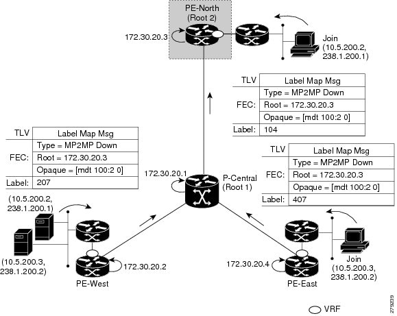
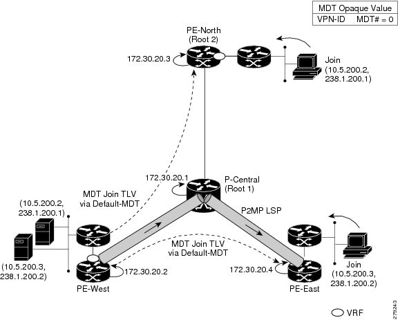
The sample output in this section displays the output after the source transmission exceeds the threshold. PE-West sends an MDT Join TLV message to signal the creation of a data MDT. In this case, the data MDT number is 1, therefore PE-East will send a label mapping message back to PE-West with a FEC TLV containing root=PE-West, Opaque value=(mdt vpn-id 1). The System ID is now changed to 4E000003 signaling a different LSP; however, the LSP-VIF is still LSP-VIF interface 0. The (S, G) entry also has the “y” flag set indicating this stream has switched to a data MDT.


PE-West# show ip mroute vrf VRF 10.5.200.3 238.1.200.2 verbose
.
.
.
(10.5.200.3, 238.1.200.2), 00:00:08/00:03:27, flags: sTy
  Incoming interface: Serial6/0, RPF nbr 192.168.10.6
    MDT TX nr: 1 LSM-ID 4E000003
  Outgoing interface list:
    Lspvif0, LSM MDT: 4E000003 (data) Forward/Sparse-Dense, 
LSP-VIF Adjacencies--PE-West

For the interface LSP-VIF, each virtual circuit represents a unique multipoint LSP forwarding instance. The correct adjacency is selected when sending the multicast packet. The sample output in this section displays the application of that concept on PE-West. There is a single LSP-VIF interface 0 interface, but it has three adjacencies as follows:

  • 4E000003 is the single data MDT created for (10.5.200.3, 238.1.200.2)

  • 58000000 is the default MDT (backup root)

  • D8000000 is the default MDT (primary root)


PE-West# show adjacency lspvif 0
   
Protocol Interface                 Address
IP       Lspvif0                   4E000003(5)
IP       Lspvif0                   58000000(4)
IP       Lspvif0                   D8000000(3)
MLDP Database Entries

The sample output in this section displays the MLDP entry for the data MDT (4E000003) on the ingress device PE-West. The following points about this entry should be noted:

  • The tree type is P2MP with PE-West (172.30.20.2) as the root.

  • The Opaque value is [mdt 100:2 1] denoting the first data MDT.

  • There are no labels allocated as it is the root.

  • There are two replication client entries on this tree.

  • Label 112 will be used to send the traffic downstream towards PE-East (via P-Central).

  • The MDT entry is an internal construct.


PE-West# show mpls mldp database id 4E000003
 
LSM ID : 4E000003 (RNR LSM ID: 8A000002)   Type: P2MP   Uptime : 00:04:54
  FEC Root           : 172.30.20.2 
  Opaque decoded     : [mdt 100:2 1]
  Opaque length      : 11 bytes
  Opaque value       : 07 000B 0000010000000100000000
  RNR active LSP     : (this entry)
  Upstream client(s) : None
  Replication client(s): 
    MDT  (VRF VRF)
      Uptime         : 00:04:54      Path Set ID  : 5000002
      Interface      : Lspvif0 
  172.30.20.1:0 
      Uptime         : 01:41:43      Path Set ID  : D9000007
      Out label (D)  : 27            Interface    : Serial4/0
      Local label (U): 112           Next Hop     : 172.30.10.1

The sample output in this section displays the database entry for the data MDT on PE-East, the egress device. Also shown is the MDT Join TLV message that was sent from PE-West over the default MDT. The MDT Join TLV message contains all the necessary information to allow PE-East to create a label mapping message P2MP LSP back to the root of PE-West. Label 414 will be used by P-Central to send traffic to PE-East.

*Feb 19 04:43:24.039: PIM(1): MDT join TLV received for (10.5.200.3,238.1.200.2)

*Feb 19 04:43:24.039: MLDP: LDP root 172.30.20.2 added

*Feb 19 04:43:24.039: MLDP: [mdt 100:2 1] label mapping msg sent to 172.30.20.1:0


PE-East# show mpls mldp database opaque_type mdt 100:2 1
LSM ID : 4E000003 (RNR LSM ID: 8A000002)   Type: P2MP   Uptime : 00:04:54
  FEC Root           : 172.30.20.2 
  Opaque decoded     : [mdt 100:2 1]
  Opaque length      : 11 bytes
  Opaque value       : 07 000B 0000010000000100000000
  RNR active LSP     : (this entry)
  Upstream client(s) : None
  Replication client(s): 
    MDT  (VRF VRF)
      Uptime         : 00:04:54      Path Set ID  : 5000002
      Interface      : Lspvif0 
LFIB Entry for the Data MDT

The sample output in this section displays the LFIB entry for the data MDT as it passes through P-Central and PE-East. The Tunnel ID used for the LSP is the Opaque value [mdt 100:2 1].


P-Central# show mpls for label 112
Local      Outgoing   Prefix           Bytes Label   Outgoing   Next Hop    
Label      Label      or Tunnel Id     Switched      interface              
111        414        [mdt 100:2 1]    2993584       Se6/0      point2point
PE-East# show mpls for label 400
 
Local      Outgoing   Prefix           Bytes Label   Outgoing   Next Hop    
Label      Label      or Tunnel Id     Switched      interface              
414   [T]  No Label   [mdt 100:2 1][V] 3297312       aggregate/green

MLDPv6-Based MVPN

The MLDPv6 based MVPN configuration enables IPv6 multicast packet delivery using MPLS. This configuration uses MPLS labels to construct default P2MP and MP2MP LSPs. The MPLS replication is used as a forwarding mechanism in the core network.

For MLDP MVPN configuration to work, ensure that the global MPLS MLDP configuration is enabled. These LSPs can be used for transporting IPv6 multicast packets, either in the global table or VPN context.

Figure 10. mLDPv6 topology
mLDPv6 topology

Restrictions for mLDPV6-Based MVPN

The following restrictions apply to the MLDPV6-Based MVPN feature:

  • mLDPV6 extranet is not supported.

  • Fast Reroute(FRR) for mLDPv6 is not supported.

  • mLDPv4 and mLDPv6 is not supported in the same Virtual Routing and Forwarding (VRF).

  • RP configuration on PE routers is not supported.

  • It is recommended to have 5 second delay while toggling IPv6 Multicast Routing for VRF.

  • Only 1 EFP per BD is supported with Bridge domain interface (BDI) in the core.

  • MLDP and MVPN coexistence is not supported in the same VRF.

mLDPv6 supported scale numbers

  • Maximum number of mVRFs supported for mLDPv6 is 20.

  • Default template supports 1000 IPv6 Mroutes.

  • IP template supports 1000 IPv6 Mroutes.

  • Video template supports 1000 IPv6 Mroutes.

Configuring mLDPv6-based MVPN

Before you begin

mLDPv6 based MVPN is configured based on the following VRF configuration:
  • MP2MP

  • P2MP

Perform following task to configure mLDPv6-based MVPN:

Enable IPv6 multicast routing on all the devices

 enable
								configure terminal
								ipv6 multicast-routing
        ipv6 multicast-routing vrf c1

Perform following task to configure mLDPv6-based MVPN:

MP2MP configuration:

vrf definition c1
rd 10:3
vpn id 10:3
route-target export 10:3
route-target import 10:3
address-family ipv6
mdt default mpls mldp 9.9.9.9
exit-address-family

Verifying the Configuration of an MLDPv6-Based MVPN

To verify the configuration, perform the following commands in privileged EXEC mode to display summary configuration information:

Identify the failing (S,G) for non-working VRF:
  • Get the mLDP PI database

  • show mpls mldp database

Show commands:
  • show ipv6 pim vrf < vrf_name > nei

  • show ipv6 pim vrf < vrf_name > inter

  • show ipv6 mfib vrf < vrf_name > < mcast_group > verb

  • show ipv6 mfib vrf < vrf_name > summary

  • show ipv6 mroute vrf < vrf_name > active

  • show ipv6 rpf vrf < vrf_name >

  • show platform hardware pp active tcam utilization mcastv6 detail <0|1>

  • show platform soft obj fp act statistics

  • show platform software object-manager FP active error-object

  • show platform hardware pp active sdm current

SUMMARY STEPS

  1. Check VRF name and Table
  2. show platform software mpls rp active forwarding-table command to display the contents of the MPLS Label Forwarding Information Base.
  3. Enter the show mpls mldp database command to display information in the MLDP database. It shows the FEC, the Opaque value of the FEC decoded, and the replication clients associated with it:
  4. Enter show ipv6 pim vrf vrf-name neighbor command to display the PIM neighbors.
  5. show ipv6 mld vrf vrf-name groups command to display mld groups.
  6. show ipv6 mroute vrf vrf-name command to display mroute entries.
  7. show ipv6 mfib vrf vrf-name command to display mFIB entries.

DETAILED STEPS


Step 1

Check VRF name and Table

Enter the show ip multicast mpls vif command to display the LSP VIFs created for all the PEs.

Example:


Device# sh ip multicast mpls vif

Interface   Next-hop             Application     Ref-Count   Table / VRF name   Flags
 Lspvif0     0.0.0.0              MDT               N/A       2    (vrf c1) 0x2
 Lspvif1     0.0.0.0              MDT               N/A       3    (vrf c2) 0x2
 Lspvif2     0.0.0.0              MDT               N/A       4    (vrf c3) 0x3
 Lspvif3     0.0.0.0              MDT               N/A       5    (vrf c4) 0x1

Step 2

show platform software mpls rp active forwarding-table command to display the contents of the MPLS Label Forwarding Information Base.

Example:


Device#  show platform software mpls rp active forwarding-table
Number of label entries in the forwarding table 0: 22

Label         Next Object      Index         Flags         Metadata
--------------------------------------------------------------------------------------------------------
0             OBJ_EOS_CHOICE   0x1b                        OM handle: 0x420b0dec
1             OBJ_EOS_CHOICE   0x1e                        OM handle: 0x420b1f34
2             OBJ_EOS_CHOICE   0x26                        OM handle: 0x420b32dc
3             OBJ_ADJ_DROP     0                           OM handle: 0x420b40a4
7             OBJ_LABEL        0x2c                        OM handle: 0x420b4c64
13            OBJ_LABEL        0x29                        OM handle: 0x420b441c
1000          OBJ_EOS_CHOICE   0x36c                       OM handle: 0x4215fd4c
1001          OBJ_LABEL        0x370                       OM handle: 0x42160654
1002          OBJ_EOS_CHOICE   0x373                       OM handle: 0x42160f5c
1003          OBJ_EOS_CHOICE   0x364                       OM handle: 0x42161864
1004          OBJ_LABEL        0x36f                       OM handle: 0x42162814
1005          OBJ_EOS_CHOICE   0x39d                       OM handle: 0x4216e934
1006          OBJ_EOS_CHOICE   0x39e                       OM handle: 0x4216f444
1007          OBJ_EOS_CHOICE   0x39f                       OM handle: 0x4216fc24
1008          OBJ_EOS_CHOICE   0x3a9                       OM handle: 0x42172b14
1009          OBJ_EOS_CHOICE   0x3ac                       OM handle: 0x4217404c
1010          OBJ_EOS_CHOICE   0x3af                       OM handle: 0x42174fb4
1011          OBJ_EOS_CHOICE   0x3b2                       OM handle: 0x42175aac
1012          OBJ_EOS_CHOICE   0x3b4                       OM handle: 0x42176694
1013          OBJ_EOS_CHOICE   0x3b6                       OM handle: 0x4217712c


Label         Next Object      Index         Flags         Metadata
--------------------------------------------------------------------------------------------------------
1014          OBJ_EOS_CHOICE   0x3b9                       OM handle: 0x42177b9c
1015          OBJ_EOS_CHOICE   0x3c5                       OM handle: 0x4217b22c

Step 3

Enter the show mpls mldp database command to display information in the MLDP database. It shows the FEC, the Opaque value of the FEC decoded, and the replication clients associated with it:

Example:


Device#  show ipv6 mfib vrf c1 FF33::1
Active Multicast Sources - sending >= 4 kbps
VRF c1
Group: FF33::1
  Source: 40::100,
   SW Rate: 0 pps/0 kbps(1sec), 0 kbps(last 205 sec)
   HW Rate: 20 pps/160 kbps(1sec)

Step 4

Enter show ipv6 pim vrf vrf-name neighbor command to display the PIM neighbors.

Example:


Device# show ipv6 pim vrf c1 neighbor
Mode: B - Bidir Capable, G - GenID Capable
Neighbor Address           Interface          Uptime    Expires  Mode DR pri

::FFFF:3.3.3.3             Lspvif0            06:57:45  00:01:33 B G     1
::FFFF:4.4.4.4             Lspvif0            06:57:44  00:01:30 B G     1
::FFFF:9.9.9.9             Lspvif0            06:57:45  00:01:34 B G  DR 1
Step 5

show ipv6 mld vrf vrf-name groups command to display mld groups.

Example:


Device#  show ipv6 mld vrf c1 groups
Group Address                           Interface                                             Uptime    Expires
FF33::1                                 BDI1                                                 00:00:26  not used

Step 6

show ipv6 mroute vrf vrf-name command to display mroute entries.

Example:


Device#  show ipv6 mroute vrf c1 FF33::1
Flags: D - Dense, S - Sparse, B - Bidir Group, s - SSM Group,
       C - Connected, L - Local, I - Received Source Specific Host Report,
       P - Pruned, R - RP-bit set, F - Register flag, T - SPT-bit set,
       J - Join SPT, Y - Joined MDT-data group,
       y - Sending to MDT-data group
       g - BGP signal originated, G - BGP Signal received,
       N - BGP Shared-Tree Prune received, n - BGP C-Mroute suppressed,
       q - BGP Src-Active originated, Q - BGP Src-Active received
       E - Extranet
Timers: Uptime/Expires
Interface state: Interface, State

(40::100, FF33::1), 00:01:01/never, flags: sTI
  Incoming interface: Lspvif1
  RPF nbr: ::FFFF:1.1.1.1
  Immediate Outgoing interface list:
    BDI1, Forward, 00:01:01/never

Step 7

show ipv6 mfib vrf vrf-name command to display mFIB entries.

Example:


Device#   show ipv6 mfib vrf c1 FF33::1 verbose
Entry Flags:    C - Directly Connected, S - Signal, IA - Inherit A flag,
                ET - Data Rate Exceeds Threshold, K - Keepalive
                DDE - Data Driven Event, HW - Hardware Installed
                ME - MoFRR ECMP entry, MNE - MoFRR Non-ECMP entry, MP - MFIB
                MoFRR Primary, RP - MRIB MoFRR Primary, P - MoFRR Primary
                MS  - MoFRR  Entry in Sync, MC - MoFRR entry in MoFRR Client.
I/O Item Flags: IC - Internal Copy, NP - Not platform switched,
                NS - Negate Signalling, SP - Signal Present,
                A - Accept, F - Forward, RA - MRIB Accept, RF - MRIB Forward,
                MA - MFIB Accept, A2 - Accept backup,
                RA2 - MRIB Accept backup, MA2 - MFIB Accept backup

Forwarding Counts: Pkt Count/Pkts per second/Avg Pkt Size/Kbits per second
Other counts:      Total/RPF failed/Other drops
I/O Item Counts:   FS Pkt Count/PS Pkt Count
VRF c1
               (40::100,FF33::1) Flags: K HW
               0x1708  OIF-IC count: 0, OIF-A count: 1
               SW Forwarding: 0/0/0/0, Other: 0/0/0
               HW Forwarding:   2323/20/1000/160, Other: 0/0/0
               Lspvif1, LSM/4 Flags: RA A MA
               BDI1 Flags: RF F NS
               CEF: Adjacency with MAC: 333300000001508789DC603F86DD
               Pkts: 0/0


Configuration Examples of mLDPv6-based MVPN

MP2MP

vrf definition c1
 rd 100:3
 vpn id 100:3
 route-target export 100:3
 route-target import 100:3
 !
 address-family ipv4
 exit-address-family
 !
address-family ipv6
 mdt default mpls mldp 9.9.9.9exit-address-family
!
ip multicast-routing distributed
ip multicast-routing vrf c1 distributed
!
ipv6 unicast-routing
ipv6 multicast-routing
ipv6 multicast-routing vrf c1
!
interface Loopback0
 ip address 1.1.1.1 255.255.255.255
 ip pim sparse-mode
 ip ospf 100 area 0
 ipv6 address 11::11/128
 ipv6 ospf 100 area 0
!
interface Loopback1
 vrf forwarding c1
 no ip address
 ip pim sparse-mode
 ipv6 address 111::113/128
 ospfv3 100 ipv6 area 0
!
interface GigabitEthernet0/4/0
 mtu 9216
 ip address 2.0.0.1 255.0.0.0
 ip ospf 100 area 0
 load-interval 30
 negotiation auto
 mpls ip
 mpls label protocol ldp
!
interface GigabitEthernet0/4/1
 no ip address
 negotiation auto
 service instance trunk 1 ethernet
  encapsulation dot1q 1-100
  rewrite ingress tag pop 1 symmetric
  bridge-domain from-encapsulation
 !
!
interface BDI1
 vrf forwarding c1
 no ip address
 load-interval 30
 ipv6 address 40::1/64
 ospfv3 100 ipv6 area 0
!
router ospfv3 100
 router-id 1.1.1.1
 !
 address-family ipv6 unicast
 exit-address-family
 !
 address-family ipv6 unicast vrf c1
 exit-address-family
!
router ospf 100
 router-id 1.1.1.1
 redistribute connected subnets
 redistribute static subnets
!
router bgp 100
 bgp log-neighbor-changes
 neighbor 3.3.3.3 remote-as 100
 neighbor 3.3.3.3 update-source Loopback0
!
 address-family ipv4
  redistribute connected
  redistribute static
  neighbor 3.3.3.3 activate
  neighbor 3.3.3.3 send-community both
exit-address-family
 !
 address-family ipv4 mvpn
  neighbor 3.3.3.3 activate
  neighbor 3.3.3.3 send-community extended
exit-address-family
 !
 address-family vpnv4
  neighbor 3.3.3.3 activate
  neighbor 3.3.3.3 send-community extended
exit-address-family
 !
 address-family ipv4 mdt
  neighbor 3.3.3.3 activate
  neighbor 3.3.3.3 send-community extended
exit-address-family
 !
 address-family vpnv6
  neighbor 3.3.3.3 activate
  neighbor 3.3.3.3 send-community both
exit-address-family
 !
 address-family ipv6 vrf c1
  redistribute connected
  redistribute static
 exit-address-family
!
ipv6 pim vrf c1 rp-address 111::113
!
mpls ldp router-id Loopback0 force
!
end

P2MP

vrf definition c1
 rd 100:3
 vpn id 100:3
 route-target export 100:3
 route-target import 100:3
 !
 address-family ipv4
 exit-address-family
 !
 address-family ipv6
  mdt default mpls mldp 9.9.9.9
  mdt data mpls mldp 500
  mdt data threshold 500
 exit-address-family
!
ip multicast-routing distributed
ip multicast-routing vrf c1 distributed
!
ipv6 unicast-routing
ipv6 multicast-routing
ipv6 multicast-routing vrf c1
!
interface Loopback0
 ip address 1.1.1.1 255.255.255.255
 ip ospf 100 area 0
 ipv6 address 11::11/128
 ipv6 ospf 100 area 0
!
interface Loopback1
 vrf forwarding c1
 no ip address
 ipv6 address 111::113/128
 ospfv3 100 ipv6 area 0
!
interface GigabitEthernet0/4/0
 mtu 9216
 ip address 2.0.0.1 255.0.0.0
 ip ospf 100 area 0
 load-interval 30
 negotiation auto
 mpls ip
 mpls label protocol ldp
!
interface GigabitEthernet0/4/1
 no ip address
 negotiation auto
 service instance trunk 1 ethernet
  encapsulation dot1q 1-100
  rewrite ingress tag pop 1 symmetric
  bridge-domain from-encapsulation
 !
!
interface BDI1
 vrf forwarding c1
 no ip address
 load-interval 30
 ipv6 address 40::1/64
 ospfv3 100 ipv6 area 0
!
router ospfv3 100
 router-id 1.1.1.1
 !
 address-family ipv6 unicast
 exit-address-family
 !
 address-family ipv6 unicast vrf c1
 exit-address-family
!
router ospf 100
 router-id 1.1.1.1
 redistribute connected subnets
 redistribute static subnets
!
router bgp 100
 bgp log-neighbor-changes
 neighbor 3.3.3.3 remote-as 100
 neighbor 3.3.3.3 update-source Loopback0
!
 address-family ipv4
  redistribute connected
  redistribute static
  neighbor 3.3.3.3 activate
  neighbor 3.3.3.3 send-community both
exit-address-family
 !
 address-family ipv4 mvpn
  neighbor 3.3.3.3 activate
  neighbor 3.3.3.3 send-community extended
exit-address-family
 !
 address-family vpnv4
  neighbor 3.3.3.3 activate
  neighbor 3.3.3.3 send-community extended
exit-address-family
 !
 address-family ipv4 mdt
  neighbor 3.3.3.3 activate
  neighbor 3.3.3.3 send-community extended
exit-address-family
 !
 address-family vpnv6
  neighbor 3.3.3.3 activate
  neighbor 3.3.3.3 send-community both
exit-address-family
 !
 address-family ipv6 vrf c1
  redistribute connected
  redistribute static
 exit-address-family
!
ipv6 pim vrf c1 rp-address 111::113
!
mpls ldp router-id Loopback0 force
!
end

MLDP Option-A and Option-C

Configuration of MLDP profile for both, VPN Option A and VPN Option C which are Layer 3 VPN (L3VPN) configurations, is supported. On both the autonomous systems, MLDP configurations should be symmetrical.

Additional References

Related Documents

Related Topic Document Title

Cisco IOS commands

https://www.cisco.com/c/en/us/td/docs/ios-xml/ios/mcl/allreleasemcl/all-book.html

Standards and RFCs

Standard/RFC Title

No specific Standards and RFCs are supported by the features in this document.

MIBs

MIB MIBs Link

To locate and download MIBs for selected platforms, Cisco IOS releases, and feature sets, use Cisco MIB Locator found at the following URL:

http://www.cisco.com/go/mibs

Technical Assistance

Description Link

The Cisco Support website provides extensive online resources, including documentation and tools for troubleshooting and resolving technical issues with Cisco products and technologies.

To receive security and technical information about your products, you can subscribe to various services, such as the Product Alert Tool (accessed from Field Notices), the Cisco Technical Services Newsletter, and Really Simple Syndication (RSS) Feeds.

Access to most tools on the Cisco Support website requires a Cisco.com user ID and password.

http://www.cisco.com/cisco/web/support/index.html