The documentation set for this product strives to use bias-free language. For the purposes of this documentation set, bias-free is defined as language that does not imply discrimination based on age, disability, gender, racial identity, ethnic identity, sexual orientation, socioeconomic status, and intersectionality. Exceptions may be present in the documentation due to language that is hardcoded in the user interfaces of the product software, language used based on RFP documentation, or language that is used by a referenced third-party product. Learn more about how Cisco is using Inclusive Language.
This module describes
how to configure Any Transport over MPLS (AToM) transports data link layer
(Layer 2) packets over a Multiprotocol Label Switching (MPLS) backbone. AToM
enables service providers to connect customer sites with existing Layer 2
networks by using a single, integrated, packet-based network infrastructure--a
Cisco MPLS network. Instead of using separate networks with network management
environments, service providers can deliver Layer 2 connections over an MPLS
backbone. AToM provides a common framework to encapsulate and transport
supported Layer 2 traffic types over an MPLS network core.
AToM supports the
following like-to-like transport types:
ATM Adaptation
Layer Type-5 (AAL5) over MPLS
ATM Cell Relay
over MPLS
Ethernet over
MPLS (VLAN and
port modes)
Circuit Emulation
(CEM)
Frame Relay over
MPLS
PPP over MPLS
High-Level Data
Link Control (HDLC) over MPLS
Note
For information on
ATM Cell relay and Circuit Emulation(CEM), see
Configuring Pseudowire.
Prerequisites for Any
Transport over MPLS
IP routing must
be configured in the core so that the provider edge (PE) routers can reach each
other via IP.
MPLS must be
configured in the core so that a label-switched path (LSP) exists between the
PE routers.
Cisco Express
Forwarding must be enabled before you configure any Layer 2 circuits.
A loopback
interface must be configured for originating and terminating Layer 2 traffic.
Ensure that the PE routers can access the other router’s loopback interface.
Note that the loopback interface is not needed in all cases. For example,
tunnel selection does not need a loopback interface when AToM is directly
mapped to a traffic engineering (TE) tunnel.
Before converting
an interface with L2TPv3 xconnect to AToM xconnect, remove the L2TPv3
configuration from the interface and then configure AToM.
Before
configuring Ethernet over MLS in VLAN mode, you must configure Ethernet over
MPLS on the subinterfaces.
General Restrictions
In a member configuration, the l2vpn xconnect context command does not prompt any error or warning, if you specify without a service instance.
The show mpls l2transport vc<vcid>detail command output displays few LDP-related information, even in case of static pseudowire.
Address
format--Configure the Label Distribution Protocol (LDP) router ID on all PE
routers to be a loopback address with a /32 mask. Otherwise, some
configurations might not function properly.
For PTPoIP configuration with explicit Null MPLS encapsulation, when a Transparent Clock (TC) is placed between a PTP primary
and a PTP subordinate, the TC does not update the correction field.
Load balancing for Layer 2 VPN traffic on a Provider router is not supported on the RSP2 Module.
Layer 2 virtual
private networks (L2VPN) features (AToM and Layer 2 Tunnel Protocol Version 3
(L2TPv3) are not supported on an ATM interface.
Some features may
not work if AToM is configured and L2TPv3 configuration is not removed
properly.
TE-FRR with BGP labels for layer 2 and layer 3 VPNs must terminate on the BGP gateway because of the four-label limitation.
If an AToM tunnel spans different service providers that exchange MPLS labels using IPv4 Border Gateway Protocol (BGP) (RFC
3107), you add a label to the stack. The maximum MPLS label stack is five (FRR label, TE label, LDP label, VPN label, VC label)four (FRR label, TE label, LDP label, VC label).
Hot standby pseudowire (HSPW) convergence without pseudowire grouping increments linearly. For example, for a thousand virtual
circuits, it requires about 54 seconds of convergence time. This is applicable only for the Cisco RSP3 Module.
Clear interface is not the recommended way to measure the convergence numbers.
With two ECMP paths, load sharing on L2VPN traffic occurs based on odd or even MPLS VC labels. If L2VPN circuits have either
odd or even MPLS VC labels, load sharing is not performed. But if L2VPN circuits have a combination of both odd and even MPLS VC labels, then the odd MPLS VC labels circuits select one link whereas the even MPLS VC labels circuits select
another link.
Flow-Aware Transport (FAT) Load Balancing over VPLS is not supported.
ATM AAL5 over MPLS
Restrictions
AAL5 over MPLS is
supported only in SDU mode.
Ethernet over MPLS (EoMPLS)
Restrictions
The subinterfaces
between the CE and PE routers that are running Ethernet over MPLS must be in
the same subnet.
The subinterface
on the adjoining CE router must be on the same VLAN as the PE router.
Ethernet over
MPLS supports VLAN packets that conform to the IEEE 802.1Q standard. The 802.1Q
specification establishes a standard method for inserting VLAN membership
information into Ethernet frames. The Inter-Switch Link (ISL) protocol is not
supported between the PE and CE routers.
The AToM control
word is supported. However, if the peer PE does not support a control word, the
control word is disabled.
Ethernet packets
with hardware-level cyclic redundancy check (CRC) errors, framing errors, and
runt packets are discarded on input.
Tunnel Selection
Restrictions
The selected path
should be an LSP destined to the peer PE router.
The selected tunnel must be an MPLS TE tunnel.
If you specify an IP address, that address must be the IP address of the loopback interface on the remote PE router. The
address must have a /32 mask. There must be an LSP destined to that selected address. The LSP need not be a TE tunnel.
Remote Ethernet Port Shutdown Restrictions
This feature is not symmetrical if the remote PE router is running an older version image or is on another platform that does
not support the EoMPLS remote Ethernet port shutdown feature and the local PE is running an image which supports this feature.
Remote Ethernet Port Shutdown is supported only on EFP with encapsulation default.
Restrictions for PPP and Multilink PPP
All member links in a Multilink PPP bundle must be on the same interface module.
All member links in a Multilink PPP bundle must be of the same bandwidth.
A maximum of 16 member links per bundle is supported.
Perform a shutdown or no shutdown of the Multilink PPP bundle to change the bundle fragmentation mode between enabled and
disabled.
Link Fragmentation and Interleaving (LFI) is not supported. However, Multilink PPP fragmentation is supported by default.
To disable fragmentation, see Disabling PPP Multilink Fragmentation section.
Multicast Multilink PPP is not supported.
PPP compression is not supported.
IPv6 is not supported for this feature.
PPP half bridging is not supported.
To enable an Address-and-Control-Field-Compression (ACFC) or Protocol-Field-Compression (PFC) configuration, perform a shutdown
or no shutdown on the serial interface.
Fractional timeslots cannot be used as memberlink in a Multilink PPP bundle.
Frame Relay (FR) and Multilink Frame Relay (MFR) are not supported.
Compressing IP or UDP or RTP headers are not supported.
PPP and Multilink PPP are supported on synchronous serial interfaces. Asynchronous serial interfaces, High-Speed Serial Interfaces
(HSSI), and ISDN interfaces are not supported.
When you configure interfaces on each end of an Multilink PPP connection with different MTU values, the link drops traffic
at high traffic rates. The configuration of the same MTU is recommended.
Information About Any Transport over MPLS
To configure AToM, you must understand the following concepts:
How AToM Transports Layer 2
Packets
AToM encapsulates
Layer 2 frames at the ingress PE and sends them to a corresponding PE at the
other end of a pseudowire, which is a connection between the two PE routers.
The egress PE removes the encapsulation and sends out the Layer 2 frame.
The successful
transmission of the Layer 2 frames between PE routers is due to the
configuration of the PE routers. You set up the connection, called a
pseudowire, between the routers. You specify the following information on each
PE router:
The type of Layer
2 data that will be transported across the pseudowire, such as Ethernet, Frame
Relay, or ATM
The IP address of
the loopback interface of the peer PE router, which enables the PE routers to
communicate
A unique
combination of peer PE IP address and VC ID that identifies the pseudowire
The following example
shows the basic configuration steps on a PE router that enable the transport of
Layer 2 packets. Each transport type has slightly different steps.
Step 1 defines the
interface or subinterface on the PE router:
Router# interface
 interface-type interface-number
Step 2 configures an ethernet service instance on an interface and enters service instance configuration mode:
Router(config-if)#service instance number ethernet WORD
Router(config-if)# service instance 393 ethernet ethernet1
Step
23 specifies the encapsulation type for the
interface, such as dot1q:
Makes a
connection to the peer PE router by specifying the LDP router ID of the peer PE
router.
Specifies a
32-bit unique identifier, called the VC ID, which is shared between the two PE
routers.
The combination of
the peer router ID and the VC ID must be unique on the router. Two circuits
cannot use the same combination of peer router ID and VC ID.
Specifies the
tunneling method used to encapsulate data in the pseudowire. AToM uses MPLS as
the tunneling method.
As an alternative,
you can set up a pseudowire class to specify the tunneling method and other
characteristics. For more information, see the
Configuring the Pseudowire Class.
How AToM Transports Layer 2 Packets Using Commands Associated with L2VPN Protocol-Based Feature
AToM encapsulates
Layer 2 frames at the ingress PE and sends them to a corresponding PE at the
other end of a pseudowire, which is a connection between the two PE routers.
The egress PE removes the encapsulation and sends out the Layer 2 frame.
The successful
transmission of the Layer 2 frames between PE routers is due to the
configuration of the PE routers. You set up the connection, called a
pseudowire, between the routers. You specify the following information on each
PE router:
The type of Layer
2 data that will be transported across the pseudowire, such as Ethernet, Frame
Relay, or ATM
The IP address of
the loopback interface of the peer PE router, which enables the PE routers to
communicate
A unique
combination of peer PE IP address and VC ID that identifies the pseudowire
The following example
shows the basic configuration steps on a PE router that enable the transport of
Layer 2 packets. Each transport type has slightly different steps.
Step 1 defines the
interface or subinterface on the PE router:
Router# interface
interface-type interface-number
Router(config)# interface gi 0/1/0
Step 2 configures an ethernet service instance on an interface and enters service instance configuration mode:
Router(config-if)#service instance number ethernet WORD
Router(config-if)# service instance 393 ethernet ethernet1
Step 3 specifies the
encapsulation type for the interface, such as dot1q:
Makes a
connection to the peer PE router by specifying the LDP router ID of the peer PE
router.
Specifies a
32-bit unique identifier, called the VC ID, which is shared between the two PE
routers.
The combination of
the peer router ID and the VC ID must be unique on the router. Two circuits
cannot use the same combination of peer router ID and VC ID.
Specifies the
tunneling method used to encapsulate data in the pseudowire. AToM uses MPLS as
the tunneling method.
Router(config)# interface pseudowire 100
Router(config-if)# encapsulation mpls
Router(config-if)# neighbor 10.0.0.1 123
Router(config-if)# exit
!
Router(config)# l2vpn xconnect context A
Router(config-xconnect)# member pseudowire 100Router(config-xconnect)# member gigabitethernet0/0/0.1Router (config-xconnect)# member gigabitethernet0/1/0 service instance 393
Router(config-xconnect)# exit
As an alternative,
you can set up a pseudowire class to specify the tunneling method and other
characteristics. For more information, see the
Configuring the Pseudowire Class.
Benefits of AToM
The following list explains some of the benefits of enabling Layer 2 packets to be sent in the MPLS network:
The AToM product set accommodates many types of Layer 2 packets, including Ethernet and Frame Relay, across multiple Cisco
router platforms. This enables the service provider to transport all types of traffic over the backbone and accommodate all
types of customers.
AToM adheres to the standards developed for transporting Layer 2 packets over MPLS. This benefits the service provider that
wants to incorporate industry-standard methodologies in the network. Other Layer 2 solutions are proprietary, which can limit
the service provider’s ability to expand the network and can force the service provider to use only one vendor’s equipment.
Upgrading to AToM is transparent to the customer. Because the service provider network is separate from the customer network,
the service provider can upgrade to AToM without disruption of service to the customer. The customers assume that they are
using a traditional Layer 2 backbone.
MPLS Traffic Engineering Fast
Reroute
AToM can use MPLS traffic engineering (TE) tunnels with fast reroute (FRR) support. AToM VCs can be rerouted around a failed
link or node at the same time as MPLS and IP prefixes.
Enabling fast reroute
on AToM does not require any special commands; you can use standard fast
reroute commands. At the ingress PE, an AToM tunnel is protected by fast
reroute when it is routed to an FRR-protected TE tunnel. Both link and node
protection are supported for AToM VCs at the ingress PE.
In the following example, the primary link is disabled, which
causes the backup tunnel (Tunnel 1) to become the primary path. The output in
boldface font shows the status of the tunnel:
Router# execute-on slot 3 debug mpls l2transport fast-reroute
========= Line Card (Slot 3) =========
AToM fast reroute debugging is on
SLOT 3:Sep 16 17:58:56.346: AToM SMGR: Processing TFIB FRR event for 10.4.0.1
SLOT 3:Sep 16 17:58:56.346: AToM SMGR: Finished processing TFIB FRR event for 10.4.0.1
SLOT 3:Sep 16 17:58:56.346: AToM SMGR: Processing TFIB FRR event for Tunnel41
SLOT 3:Sep 16 17:58:56.346: AToM SMGR: Finished processing TFIB FRR event for Tunnel41
Sep 16 17:58:58.342: %LINK-3-UPDOWN: Interface POS0/0/0, changed state to down
Sep 16 17:58:58.342: %OSPF-5-ADJCHG: Process 1, Nbr 10.0.0.1 on POS0/0 from FULL to DOWN, Neighbor Down: Interface down or detached
Sep 16 17:58:59.342: %LINEPROTO-5-UPDOWN: Line protocol on Interface POS0/0/0, changed state to down
Maximum Transmission Unit
Guidelines for Estimating Packet Size
The following
calculation helps you determine the size of the packets traveling through the
core network. You set the maximum transmission unit (MTU) on the core-facing
interfaces of the P and PE routers to accommodate packets of this size. The MTU
should be greater than or equal to the total bytes of the items in the
following equation:
Core MTU >= (Edge MTU + Transport header + AToM header + (MPLS label stack * MPLS label size))
The following
sections describe the variables used in the equation.
Edge MTU
The edge MTU is the
MTU for the customer-facing interfaces.
Transport Header
The Transport
header depends on the transport type. The table below lists the specific sizes
of the headers.
Table 1. Header Size of Packets
Transport
Type
Packet Size
AAL5
0-32 bytes
Ethernet
VLAN
18 bytes
Ethernet
Port
14 bytes
Frame Relay
DLCI
2 bytes for Cisco encapsulation, 8 bytes for Internet Engineering Task Force (IETF) encapsulation
HDLC
4 bytes
PPP
4 bytes
AToM Header
The AToM header is
4 bytes (control word). The control word is optional for Ethernet, PPP, HDLC,
and cell relay transport types. The control word is required for Frame Relay
and ATM AAL5 transport types.
MPLS Label Stack
The MPLS label
stack size depends on the configuration of the core MPLS network:
AToM uses one
MPLS label to identify the AToM VCs (VC label). Therefore, the minimum MPLS
label stack is one for directly connected AToM PEs, which are PE routers that
do not have a P router between them.
If LDP is used
in the MPLS network, the label stack size is two (the LDP label and the VC
label).
If a TE tunnel instead of LDP is used between PE routers in the MPLS network, the label stack size is two (the TE label and
the VC label).
If a TE tunnel and LDP are used in the MPLS network (for example, a TE tunnel between P routers or between P and PE routers,
with LDP on the tunnel), the label stack is three (TE label, LDP label, VC label).
If you use MPLS fast reroute in the MPLS network, you add a label to the stack. The maximum MPLS label stack in this case
is four (FRR label, TE label, LDP label, VC label).
If AToM is used by the customer carrier in an MPLS VPN Carrier Supporting Carrier environment, you add a label to the stack.
The maximum MPLS label stack in the provider carrier network is five (FRR label, TE label, LDP label, VPN label, VC label)four (FRR label, TE label, LDP label, VC label).
BGP PIC Edge with EoMPLS using BGP label Unicast (RFC 3107) requires the bgp mpls-local-label command to be explicitly enabled under the Router BGP process. This limitation is applicable only on the Cisco RSP3 module.
If an AToM tunnel spans different service providers that exchange MPLS labels using IPv4 Border Gateway Protocol (BGP) (RFC
3107), you add a label to the stack. The maximum MPLS label stack is five (FRR label, TE label, LDP label, VPN label, VC label)four (FRR label, TE label, LDP label, VC label)
TE-FRR with BGP labels for layer 2 and layer 3 VPNs must terminate on the BGP gateway because of the four-label limitation.
Other circumstances
can increase the MPLS label stack size. Therefore, analyze the complete data
path between the AToM tunnel endpoints and determine the maximum MPLS label
stack size for your network. Then multiply the label stack size by the size of
the MPLS label.
Estimating Packet Size Example
The estimated packet size in the following example is 1526 bytes, based on the following assumptions:
The edge MTU is 1500 bytes.
The transport type is Ethernet VLAN, which designates 18 bytes for the transport header.
The AToM header is 0, because the control word is not used.
The MPLS label stack is 2, because LDP is used. The MPLS label is 4 bytes.
Edge MTU + Transport header + AToM header + (MPLS label stack * MPLS label) = Core MTU
1500     + 18                    + 0      + (2                * 4         ) = 1526
You must configure the P and PE routers in the core to accept packets of 1526 bytes.
QoS Features Supported with
AToM
The tables below list
the QoS features supported by AToM.
Table 2. QoS Features Supported with
Ethernet over MPLS
QoS Feature
Ethernet over
MPLS
Service
policy
Can be
applied to:
Interface
(input and output)
Classification
Supports the
following commands:
matchcos (on interfaces)
matchmplsexperimental (on interfaces)
matchqos-group (on interfaces) (output policy)
Marking
Supports the
following commands:
setcos (output policy)
setdiscard-class (input policy)
setmplsexperimental(input policy) (on interfaces)
setqos-group (input policy)
Policing
Supports the
following:
Color-aware policing
Multiple-action policing
Single-rate policing
Two-rate
policing
Queueing and
shaping
Supports the
following:
Byte-based WRED
Low
Latency Queueing (LLQ)
Weighted
Random Early Detection (WRED)
Table 3. QoS Features Supported with
Frame Relay over MPLS
QoS Feature
Frame Relay
over MPLS
Service
policy
Can be
applied to:
Interface
(input and output)
PVC
(input and output)
Classification
Supports
the following commands:
matchfr-de (on interfaces and VCs)
matchfr-dlci(on interfaces)
matchqos-group
Marking
Supports
the following commands:
frame-relaycongestionmanagement (output)
setdiscard-class
setfr-de (output policy)
setfr-fecn-becn (output)
setmplsexperimental
setqos-group
thresholdecn (output)
Policing
Supports
the following:
Color-aware policing
Multiple-action policing
Single-rate policing
Two-rate policing
Queueing
and shaping
Supports
the following:
Byte-based WRED
Class-based weighted fair queueing (CBWFQ)
LLQ
random-detectdiscard-class-based command
Traffic
shaping
WRED
Table 4. QoS Features Supported with
ATM Cell Relay and AAL5 over MPLS
QoS Feature
ATM Cell
Relay and AAL5 over MPLS
Service
policy
Can be
applied to:
Interface (input and output)
PVC
(input and output)
Subinterface (input and output)
Classification
Supports
the following commands:
matchmplsexperimental (on VCs)
matchqos-group (output)
Marking
Supports
the following commands:
random-detectdiscard-class-based (input)
setclp (output) (on interfaces, subinterfaces, and VCs)
setdiscard-class (input)
setmplsexperimental (input) (on interfaces, subinterfaces, and VCs)
setqos-group (input)
Policing
Supports
the following:
Color-aware policing
Multiple-action policing
Single-rate policing
Two-rate policing
Queueing
and shaping
Supports
the following:
Byte-based WRED
CBWFQ
Class-based shaping support on ATM PVCs
LLQ
random-detectdiscard-class-basedcommand
WRED
Any Transport over MPLS
(AToM) Remote Ethernet Port Shutdown
This Cisco IOS XE
feature allows a service provider edge (PE) router on the local end of an
Ethernet over MPLS (EoMPLS) pseudowire to detect a remote link failure and
cause the shutdown of the Ethernet port on the local customer edge (CE) router.
Because the Ethernet port on the local CE router is shut down, the router does
not lose data by continuously sending traffic to the failed remote link. This
is beneficial if the link is configured as a static IP route.
The figure below
illustrates a condition in an EoMPLS WAN, with a down Layer 2 tunnel link
between a CE router (Customer Edge 1) and the PE router (Provider Edge 1). A CE
router on the far side of the Layer 2 tunnel (Customer Edge 2), continues to
forward traffic to Customer Edge 1 through the L2 tunnel.
Figure 1. Remote Link Outage in EoMPLS
WAN
Previous to this
feature, the Provider Edge 2 router could not detect a failed remote link.
Traffic forwarded from Customer Edge 2 to Customer Edge 1 would be lost until
routing or spanning tree protocols detected the down remote link. If the link
was configured with static routing, the remote link outage would be even more
difficult to detect.
With this feature,
the Provider Edge 2 router detects the remote link failure and causes a
shutdown of the local Customer Edge 2 Ethernet port. When the remote L2 tunnel
link is restored, the local interface is automatically restored as well. The
possibility of data loss is thus diminished.
With reference to the
figure above, the Remote Ethernet Shutdown sequence is generally described as
follows:
The remote link
between Customer Edge 1 and Provider Edge 1 fails.
Provider Edge 2
detects the remote link failure and disables the transmit laser on the line
card interface connected to Customer Edge 2.
An RX_LOS error
alarm is received by Customer Edge 2 causing Customer Edge 2 to bring down the
interface.
Provider Edge 2
maintains its interface with Customer Edge 2 in an up state.
When the remote
link and EoMPLS connection is restored, the Provider Edge 2 router enables the
transmit laser.
The Customer Edge
2 router brings up its downed interface.
This feature is
enabled by default for Ethernet over MPLS (EoMPLS). You can also enable this
feature by using the
remotelinkfailurenotification command in xconnect configuration
mode as shown in the following example:
This feature can be
disabled using the
noremotelinkfailurenotification command in xconnect configuration
mode. Use theshowipinterfacebrief privileged EXEC command to display the
status of all remote L2 tunnel links. Use the
showinterface privileged EXEC command to show the
status of the L2 tunnel on a specific interface.
Note
The
noremotelinkfailurenotification command will not give notification to
clients for remote attachment circuit status down.
Note
Remote Ethernet Port Shutdown is supported only on EFP with encapsulation default.
Any Transport over MPLS (AToM) Remote Ethernet Port Shutdown Using Commands Associated with L2VPN Protocol-Based Feature
This Cisco IOS XE
feature allows a service provider edge (PE) router on the local end of an
Ethernet over MPLS (EoMPLS) pseudowire to detect a remote link failure and
cause the shutdown of the Ethernet port on the local customer edge (CE) router.
Because the Ethernet port on the local CE router is shut down, the router does
not lose data by continuously sending traffic to the failed remote link. This
is beneficial if the link is configured as a static IP route.
The figure below
illustrates a condition in an EoMPLS WAN, with a down Layer 2 tunnel link
between a CE router (Customer Edge 1) and the PE router (Provider Edge 1). A CE
router on the far side of the Layer 2 tunnel (Customer Edge 2), continues to
forward traffic to Customer Edge 1 through the L2 tunnel.
Figure 2. Remote Link Outage in EoMPLS
WAN
Previous to this
feature, the Provider Edge 2 router could not detect a failed remote link.
Traffic forwarded from Customer Edge 2 to Customer Edge 1 would be lost until
routing or spanning tree protocols detected the down remote link. If the link
was configured with static routing, the remote link outage would be even more
difficult to detect.
With this feature,
the Provider Edge 2 router detects the remote link failure and causes a
shutdown of the local Customer Edge 2 Ethernet port. When the remote L2 tunnel
link is restored, the local interface is automatically restored as well. The
possibility of data loss is thus diminished.
With reference to the
figure above, the Remote Ethernet Shutdown sequence is generally described as
follows:
The remote link
between Customer Edge 1 and Provider Edge 1 fails.
Provider Edge 2
detects the remote link failure and disables the transmit laser on the line
card interface connected to Customer Edge 2.
An RX_LOS error
alarm is received by Customer Edge 2 causing Customer Edge 2 to bring down the
interface.
Provider Edge 2
maintains its interface with Customer Edge 2 in an up state.
When the remote
link and EoMPLS connection is restored, the Provider Edge 2 router enables the
transmit laser.
The Customer Edge
2 router brings up its downed interface.
This feature is
enabled by default for Ethernet over MPLS (EoMPLS). You can also enable this
feature by using the
remotelinkfailurenotification command in xconnect configuration
mode as shown in the following example:
template type pseudowire eompls
 encapsulation mpls
!
interface Pseudowire 100
 source template type pseudowire test
 neighbor 10.13.13.13 1
interface GigabitEthernet1/0/0
	service instance 300 ethernet
 encapsulation default
 xconnect 10.1.1.1 1 encapsulation mpls
 remote link failure notification
l2vpn xconnect context con1
 member GigabitEthernet1/0/0 service-instance 300
 member Pseudowire 100
!
l2vpn xconnect context con1
member GigabitEthernet1/0/0 service-instance 300
member Pseudowire 100
remote link failure notification
This feature can be
disabled using the
noremotelinkfailurenotification command in xconnect configuration
mode. Use theshowipinterfacebrief privileged EXEC command to display the
status of all remote L2 tunnel links. Use the
showinterface privileged EXEC command to show the
status of the L2 tunnel on a specific interface.
Note
The
noremotelinkfailurenotification command will not give notification to
clients for remote attachment circuit status down.
AToM Load Balancing with
Single PW
Prior to Cisco IOS XE Release 3.4S, the Cisco ASR 1000
Series Aggregation Services Router did not perform load balancing for packets
within the same pseudowire (PW) at the Provide Edge (PE) even if Equal Cost
Multiple Paths (ECMPs) were available between PEs in an MPLS cloud. Only one of
the routing options from the table would be used, and the other paths would be
left unused.
The AToM Load Balancing with Single PW feature enables load balancing
for packets within the same pseudowire by further classifying packets within
the same pseudowire into different flows based on certain fields in the packet
received on an attachment circuit. For example, for Ethernet this load
balancing is based on the source MAC address in the incoming packets.
In Cisco IOS XE Release 3.4S, this feature is available
only for the Ethernet family of attachment circuits (ACs); so the
flow-identification logic is based on source MAC address. All packets with the
same source MAC address follow one path and are identified as flows.
How to Configure Any Transport over MPLS
This section explains how to perform a basic AToM configuration and includes the following procedures:
Configuring the Pseudowire Class
Note
In simple configurations, this task is optional. You need not specify a pseudowire class if you specify the tunneling method
as part of the xconnect command.
You must specify the encapsulationmpls command as part of the pseudowire class or as part of the xconnect command for the AToM VCs to work properly. If you omit the encapsulationmpls command as part of the xconnect command, you receive the following error:
% Incomplete command.
Procedure
Step 1
enable
Example:
Router> enable
Enables privileged EXEC mode.
Enter your password if prompted.
Step 2
configureterminal
Example:
Router# configure terminal
Enters global configuration mode.
Step 3
pseudowire-classname
Example:
Router(config)# pseudowire-class atom
Establishes a pseudowire class with a name that you specify and enters pseudowire class configuration mode.
Step 4
encapsulationmpls
Example:
Router(config-pw)# encapsulation mpls
Specifies the tunneling encapsulation.
Configuring the Pseudowire Class Using Commands Associated with L2VPN Protocol-Based Feature
Note
In simple configurations, this task is optional. You need not specify a pseudowire class if you specify the tunneling method
as part of the l2vpnxconnectcontext command.
You must specify the encapsulationmpls command as part of the pseudowire class or as part of the l2vpnxconnectcontext command for the AToM VCs to work properly. If you omit the encapsulationmpls command as part of the l2vpnxconnectcontextcommand, you receive the following error:
% Incomplete command.
Procedure
Step 1
enable
Example:
Router> enable
Enables privileged EXEC mode.
Enter your password if prompted.
Step 2
configureterminal
Example:
Router# configure terminal
Enters global configuration mode.
Step 3
interfacepseudowirename
Example:
Router(config)# interface pseudowire atom
Establishes an interface pseudowire with a name that you specify and enters pseudowire class configuration mode.
Step 4
encapsulationmpls
Example:
Router(config-pw-class)# encapsulation mpls
Specifies the tunneling encapsulation.
Step 5
neighborpeer-address vcid-value
Example:
Router(config-pw-class)# neighbor 33.33.33.33 1
Specifies the peer IP address and virtual circuit (VC) ID value of a Layer 2 VPN (L2VPN) pseudowire.
Changing the Encapsulation
Type and Removing a Pseudowire
Once you specify the
encapsulationmpls command, you cannot remove it using the
noencapsulationmpls command.
Nor can you change the command's setting using
the
encapsulationl2tpv3 command.
Those methods result in the following error message:
Encapsulation changes are not allowed on an existing pw-class.
To remove the
encapsulationmpls command, you must delete the pseudowire with
the
nopseudowire-class command.
To change the type of
encapsulation, remove the pseudowire using the
nopseudowire-class command and reconfigure the
pseudowire to specify the new encapsulation type.
Changing the Encapsulation Type and Removing a Pseudowire Using Commands Associated with the L2VPN Protocol-Based Feature
Once you specify
the
encapsulationmpls command, you cannot remove it using the
noencapsulationmpls command.
Nor can you change the command's setting using
the
encapsulationl2tpv3 command.
Those methods result in the following error message:
Encapsulation changes are not allowed on an existing pw-class.
% Cannot remove encapsulation on existing pseudowire
To remove the encapsulationmpls command, you must delete the pseudowire with the nointerfacepseudowire command.
To change the type
of encapsulation, remove the pseudowire using the
notemplatetypepseudowire command and reconfigure the pseudowire
to specify the new encapsulation type.
Configuring ATM AAL5 over
MPLS
Configuring ATM AAL5 over MPLS on PVCs
Procedure
Step 1
enable
Example:
Router> enable
Enables privileged EXEC mode.
Enter your password if prompted.
Step 2
configureterminal
Example:
Router# configure terminal
Enters global configuration mode.
Step 3
interfacetypeslot/subslot/port[.subinterface]
Example:
Router(config)# interface atm1/0/0
Specifies the interface type and enters interface configuration mode.
Step 4
pvc [name] vpi/vcil2transport
Example:
Router(config-if)# pvc 1/200 l2transport
Creates or assigns a name to an ATM PVC and enters L2transport PVC configuration mode.
The l2transport keyword indicates that the PVC is a switched PVC instead of a terminated PVC.
Displays output that shows ATM AAL5 over MPLS is configured on a PVC.
Examples
The following is sample output from the showmplsl2transportvc command that shows that ATM AAL5 over MPLS is configured on a PVC:
Router# show mpls l2transport vc
Local intf   Local circuit          Dest address      VC ID      Status
---------    -------------          ------------      -----      ------
ATM1/0       ATM AAL5 1/100         10.4.4.4           100        UP
Configuring ATM AAL5 over MPLS on PVCs using the commands associated with the L2VPN Protocol-Based CLIs feature
Procedure
Step 1
enable
Example:
Device> enable
Enables privileged EXEC mode.
Enter your password if prompted.
Step 2
configureterminal
Example:
Device# configure terminal
Enters global configuration mode.
Step 3
interfacetypeslot/subslot/port[.subinterface]
Example:
Device(config)# interface atm1/0/0
Specifies the interface type and enters interface configuration mode.
Step 4
pvc [name] vpi/vcil2transport
Example:
Device(config-if)# pvc 1/200 l2transport
Creates or assigns a name to an ATM PVC and enters L2transport PVC configuration mode.
The l2transport keyword indicates that the PVC is a switched PVC instead of a terminated PVC.
Specifies ATM AAL5 encapsulation for the PVC. Make sure you specify the same encapsulation type on the PE and customer edge
(CE) routers.
Step 6
end
Example:
Device(config-if-atm-l2trans-pvc)# end
Exits to privileged EXEC mode.
Step 7
interfacepseudowirenumber
Example:
Device(config)# interface pseudowire 100
Specifies the pseudowire interface and enters interface configuration mode.
Step 8
encapsulationmpls
Example:
Device(config-if)# encapsulation mpls
Specifies that Multiprotocol Label Switching (MPLS) is used as the data encapsulation method.
Step 9
neighborpeer-addressvcid-value
Example:
Device(config-if)# neighbor 10.13.13.13 100
Specifies the peer IP address and virtual circuit (VC) ID value of the Layer 2 VPN (L2VPN) pseudowire.
Step 10
exit
Example:
Device(config-if)# exit
Exits interface configuration mode.
Step 11
l2vpnxconnectcontextcontext-name
Example:
Device(config)# l2vpn xconnect context con1
Creates a Layer 2 VPN (L2VPN) cross connect context and enters xconnect configuration mode.
Step 12
memberpseudowireinterface-number
Example:
Device(config-xconnect)# member pseudowire 100
Specifies a member pseudowire to form a Layer 2 VPN (L2VPN) cross connect.
Step 13
memberatminterface-numberpvcvpi/vci
Example:
Device(config-xconnect)# member atm 100 pvc 1/200
Specifies the location of the ATM member interface.
Step 14
end
Example:
Device(config-xconnect)# end
Exits to privileged EXEC mode.
Step 15
showl2vpnatomvc
Example:
Device# show l2vpn atom vc
Displays output that shows ATM AAL5 over MPLS is configured on a PVC.
Examples
The following is sample output from the showl2vpnatomvc command that shows that ATM AAL5 over MPLS is configured on a PVC:
Device# show l2vpn atom vc
Local intf   Local circuit          Dest address      VC ID      Status
---------    -------------          ------------      -----      ------
ATM1/0       ATM AAL5 1/100         10.4.4.4           100        UP
Configuring ATM AAL5 over MPLS in VC Class Configuration Mode
Procedure
Step 1
enable
Example:
Router> enable
Enables privileged EXEC mode.
Enter your password if prompted.
Step 2
configureterminal
Example:
Router# configure terminal
Enters global configuration mode.
Step 3
vc-classatmvc-class-name
Example:
Router(config)# vc-class atm aal5class
Creates a VC class and enters VC class configuration mode.
Step 4
encapsulationlayer-type
Example:
Router(config-vc-class)# encapsulation aal5
Configures the AAL and encapsulation type.
Step 5
exit
Example:
Router(config-vc-class)# exit
Exits VC class configuration mode.
Step 6
interfacetypeslot/subslot/port[.subinterface]
Example:
Router(config)# interface atm1/0/0
Specifies the interface type enters interface configuration mode.
Step 7
class-intvc-class-name
Example:
Router(config-if)# class-int aal5class
Applies a VC class to the ATM main interface or subinterface.
Note
You can also apply a VC class to a PVC.
Step 8
pvc [name] vpi/vcil2transport
Example:
Router(config-if)# pvc 1/200 l2transport
Creates or assigns a name to an ATM PVC and enters L2transport PVC configuration mode.
The l2transport keyword indicates that the PVC is a switched PVC instead of a terminated PVC.
Displays the type of encapsulation and that the VC class was applied to an interface.
Examples
In the following example, the command output from the showatmclass-links command verifies that ATM AAL5 over MPLS is configured as part of a VC class. The command output shows the type of encapsulation
and that the VC class was applied to an interface.
Router# show atm class-links 1/100
Displaying vc-class inheritance for ATM1/0/0.0, vc 1/100:
no broadcast - Not configured - using default
encapsulation aal5 - VC-class configured on main interface
Configuring ATM AAL5 over MPLS in VC Class Configuration Mode using the commands associated with the L2VPN Protocol-Based
CLIs feature
Procedure
Step 1
enable
Example:
Router> enable
Enables privileged EXEC mode.
Enter your password if prompted.
Step 2
configureterminal
Example:
Router# configure terminal
Enters global configuration mode.
Step 3
vc-classatmvc-class-name
Example:
Router(config)# vc-class atm aal5class
Creates a VC class and enters VC class configuration mode.
Step 4
encapsulationlayer-type
Example:
Router(config-vc-class)# encapsulation aal5
Configures the AAL and encapsulation type.
Step 5
exit
Example:
Router(config-vc-class)# exit
Exits VC class configuration mode.
Step 6
interfacetypeslot/subslot/port[.subinterface]
Example:
Router(config)# interface atm1/0/0
Specifies the interface type enters interface configuration mode.
Step 7
class-intvc-class-name
Example:
Router(config-if)# class-int aal5class
Applies a VC class to the ATM main interface or subinterface.
Note
You can also apply a VC class to a PVC.
Step 8
pvc [name] vpi/vcil2transport
Example:
Router(config-if)# pvc 1/200 l2transport
Creates or assigns a name to an ATM PVC and enters L2transport PVC configuration mode.
The l2transport keyword indicates that the PVC is a switched PVC instead of a terminated PVC.
Step 9
exit
Example:
Router(config-if)# exit
Exits interface configuration mode.
Step 10
interfacepseudowirenumber
Example:
Router(config)# interface pseudowire 100
Specifies the pseudowire interface and enters interface configuration mode.
Step 11
encapsulationmpls
Example:
Router(config-if)# encapsulation mpls
Specifies that Multiprotocol Label Switching (MPLS) is used as the data encapsulation method.
Step 12
neighborpeer-addressvcid-value
Example:
Router(config-if)# neighbor 10.0.0.1 123
Specifies the peer IP address and virtual circuit (VC) ID value of the Layer 2 VPN (L2VPN) pseudowire.
Step 13
exit
Example:
Router(config-if)# exit
Exits interface configuration mode.
Step 14
l2vpnxconnectcontextcontext-name
Example:
Router(config)# l2vpn xconnect context con1
Creates a Layer 2 VPN (L2VPN) cross connect context and enters xconnect configuration mode.
Step 15
memberpseudowireinterface-number
Example:
Router(config-xconnect)# member pseudowire 100
Specifies a member pseudowire to form a Layer 2 VPN (L2VPN) cross connect.
Step 16
memberatminterface-number
Example:
Device(config-xconnect)# member atm 100
Specifies the location of the ATM member interface.
Step 17
end
Example:
Router(config-if-atm-l2trans-pvc)# end
Exits to privileged EXEC mode.
Step 18
showatmclass-links
Example:
Router# show atm class-links
Displays the type of encapsulation and that the VC class was applied to an interface.
Examples
In the following example, the command output from the showatmclass-links command verifies that ATM AAL5 over MPLS is configured as part of a VC class. The command output shows the type of encapsulation
and that the VC class was applied to an interface.
Router# show atm class-links 1/100
Displaying vc-class inheritance for ATM1/0/0.0, vc 1/100:
no broadcast - Not configured - using default
encapsulation aal5 - VC-class configured on main interface
Configuring Ethernet over MPLS
Configuring Ethernet over MPLS in VLAN Mode to Connect Two VLAN Networks That Are in Different Locations.
Configuring Ethernet over MPLS in VLAN Mode to Connect Two VLAN Networks That Are in Different Locations using the commands
associated with the L2VPN Protocol-Based CLIs feature
Displays information about Ethernet over MPLS port mode.
Examples
The sample output in the following example shows two VCs for Ethernet over MPLS:
VC 2 is in Ethernet VLAN mode.
VC 8 is in Ethernet port mode.
Router# show mpls l2transport vc
Local intf     Local circuit        Dest address    VC ID      Status
-------------  -------------------- --------------- ---------- ----------
Gi4/0/0.1      Eth VLAN 2           10.1.1.1        2          UP
Gi8/0/1        Ethernet             10.1.1.1        8          UP
The sample output from the showmplsl2transportvcdetail command displays the same information in a different format:
Router# show mpls l2transport vc detail
Local interface: Gi4/0/0.1 up, line protocol up, Eth VLAN 2 up
Destination address: 10.1.1.1, VC ID: 2, VC status: up
.
.
.
Local interface: Gi8/0/1 up, line protocol up, Ethernet up
  Destination address: 10.1.1.1, VC ID: 8, VC status: up
Configuring Ethernet over MPLS in Port Mode Using Commands Associated with the L2VPN Protocol-Based Feature
Specifies the Gigabit Ethernet interface and enters interface configuration mode.
Make sure the interface on the adjoining CE router is on the same VLAN as this PE router.
Step 4
end
Example:
Device(config-if)# end
Exits to privileged EXEC mode.
Step 5
interfacepseudowirenumber
Example:
Device(config)# interface pseudowire 100
Specifies the pseudowire interface and enters interface configuration mode.
Step 6
encapsulationmpls
Example:
Device(config-if)# encapsulation mpls
Specifies that Multiprotocol Label Switching (MPLS) is used as the data encapsulation method.
Step 7
neighborpeer-addressvcid-value
Example:
Device(config-if)# neighbor 10.0.0.1 123
Specifies the peer IP address and virtual circuit (VC) ID value of the Layer 2 VPN (L2VPN) pseudowire.
Step 8
exit
Example:
Device(config-if)# exit
Exits interface configuration mode.
Step 9
l2vpnxconnectcontextcontext-name
Example:
Device(config)# l2vpn xconnect context con1
Creates a Layer 2 VPN (L2VPN) cross connect context and enters xconnect configuration mode.
Step 10
memberpseudowireinterface-number
Example:
Device(config-xconnect)# member pseudowire 100
Specifies a member pseudowire to form a Layer 2 VPN (L2VPN) cross connect.
Step 11
membergigabitethernetinterface-number
Example:
Device(config-xconnect)# member GigabitEthernet0/0/0.1
Specifies the location of the Gigabit Ethernet member interface.
Step 12
end
Example:
Device(config-xconnect)# end
Exits to privileged EXEC mode.
Step 13
end
Example:
Device(config-if)# end
Exits to privileged EXEC mode.
Step 14
showl2vpnatomvc
Example:
Device# show l2vpn atom vc
Displays information about Ethernet over MPLS port mode.
Examples
The sample output in the following example shows two VCs for Ethernet over MPLS:
VC 2 is in Ethernet VLAN mode.
VC 8 is in Ethernet port mode.
Device# show l2vpn atom vc
Service Interface    Dest Address   VC ID  Type  Name    Status
-----------------    ------------  ------  ----  ----   ------
pw100                 10.1.1.1        2          FOO     UP
pw200                 10.1.1.1        8    p2p   FOO     UP
Configuring Ethernet over MPLS with VLAN ID Rewrite
Binds the attachment circuit to a pseudowire VC and enters xconnect configuration mode.
Step 9
remotecircuitidremote-vlan-id
Example:
Router(config-subif-xconn)# remote circuit id 101
(Optional) Enables you to use VLAN interfaces with different VLAN IDs at both ends of the tunnel.
Step 10
end
Example:
Router(config-subif-xconn)# end
Exits to privileged EXEC mode.
Step 11
showcontrollerseomplsforwarding-table
Example:
Router# show controllers eompls forwarding-table
Displays information about VLAN ID rewrite.
Examples
The following sample output from the showcontrollerseomplsforwarding-table command shows VLAN ID rewrite configured on a router with an engine 2 3-port Gigabit Ethernet line card. In this example,
the output in boldface font shows the VLAN ID rewrite information.
Router# execute slot 0 show controllers eompls forwarding-table 0 2
Port # 0, VLAN-ID # 2, Table-index 2
EoMPLS configured: 1
tag_rew_ptr             = D001BB58
Leaf entry?     = 1
FCR index       = 20
           **tagrew_psa_addr    = 0006ED60
           **tagrew_vir_addr    = 7006ED60
           **tagrew_phy_addr    = F006ED60
        [0-7] loq 8800 mtu 4458  oq 4000 ai 3 oi 04019110 (encaps size 4)
        cw-size 4 vlanid-rew 3
        gather A30 (bufhdr size 32 EoMPLS (Control Word) Imposition profile 81)
        2 tag: 18 18
        counters 1182, 10 reported 1182, 10.
    Local OutputQ (Unicast):    Slot:2  Port:0  RED queue:0  COS queue:0
    Output Q (Unicast):         Port:0          RED queue:0  COS queue:0
Router# execute slot 0 show controllers eompls forwarding-table 0 3
Port # 0, VLAN-ID # 3, Table-index 3
EoMPLS configured: 1
tag_rew_ptr             = D0027B90
Leaf entry?     = 1
FCR index       = 20
           **tagrew_psa_addr    = 0009EE40
           **tagrew_vir_addr    = 7009EE40
           **tagrew_phy_addr    = F009EE40
        [0-7] loq 9400 mtu 4458  oq 4000 ai 8 oi 84000002 (encaps size 4)
        cw-size 4 vlanid-rew 2
        gather A30 (bufhdr size 32 EoMPLS (Control Word) Imposition profile 81)
        2 tag: 17 18
        counters 1182, 10 reported 1182, 10.
    Local OutputQ (Unicast):    Slot:5  Port:0  RED queue:0  COS queue:0
    Output Q (Unicast):         Port:0          RED queue:0  COS queue:0
Configuring Ethernet over MPLS with VLAN ID Rewrite Using Commands Associated with the L2VPN Protocol-Based Feature
Specifies the Gigabit Ethernet subinterface and enters subinterface configuration mode.
Step 4
interfacegigabitethernetslot/subslot/port
Example:
Router(config)# interface gigabitethernet4/0/0
Specifies the Gigabit Ethernet subinterface and enters subinterface configuration mode.
Step 5
service instancenumberethernetnumber
Example:
Router(config-if)#service instance 393 ethernet
Step 6
encapsulationdot1qvlan-id
Example:
Router(config-subif)# encapsulation dot1q 100
Enables the subinterface to accept 802.1Q VLAN packets.
Step 7
end
Example:
Router(config-subif)# end
Exits to privileged EXEC mode.
Step 8
interfacepseudowirenumber
Example:
Router(config)# interface pseudowire 100
Specifies the pseudowire interface and enters interface configuration mode.
Step 9
encapsulationmpls
Example:
Router(config-if)# encapsulation mpls
Specifies that Multiprotocol Label Switching (MPLS) is used as the data encapsulation method.
Step 10
neighborpeer-addressvcid-value
Example:
Router(config-if)# neighbor 10.0.0.1 123
Specifies the peer IP address and virtual circuit (VC) ID value of the Layer 2 VPN (L2VPN) pseudowire.
Step 11
exit
Example:
Router(config-if)# exit
Exits interface configuration mode.
Step 12
l2vpnxconnectcontextcontext-name
Example:
Router(config)# l2vpn xconnect context con1
Creates a Layer 2 VPN (L2VPN) cross connect context and enters xconnect configuration mode.
Step 13
memberpseudowireinterface-number
Example:
Router(config-xconnect)# member pseudowire 100
Specifies a member pseudowire to form a Layer 2 VPN (L2VPN) cross connect.
Step 14
membergigabitethernetinterface-number
Example:
Router(config-xconnect)# member GigabitEthernet0/0/0.1
Router(config-xconnect)# member gigabitethernet4/0/0 service-instance 393
Specifies the location of the Gigabit Ethernet member interface.
Step 15
remotecircuitidremote-vlan-id
Example:
Router(config-xconnect)# remote circuit id 101
(Optional) Enables you to use VLAN interfaces with different VLAN IDs at both ends of the tunnel.
Step 16
end
Example:
Router(config-xconnect)# end
Exits to privileged EXEC mode.
Step 17
showcontrollerseomplsforwarding-table
Example:
Router# show controllers eompls forwarding-table
Displays information about VLAN ID rewrite.
ExamplesExample
RSP3-RT1#show ethernet service instance id HYPERLINK "tel:1002"1002 interface gi 0/1/0 det
Service Instance ID: HYPERLINK "tel:1002"1002
Service Instance Type: Static
Associated Interface: GigabitEthernet0/1/0
Associated EVC:
L2protocol drop
CE-Vlans:
Encapsulation: dot1q HYPERLINK "tel:1002"1002 vlan protocol type 0xHYPERLINK "tel:8100"8100
Rewrite: ingress tag pop 1 symmetric
Interface Dot1q Tunnel Ethertype: 0xHYPERLINK "tel:8100"8100
State: Up
EFP Statistics:
Pkts In   Bytes In   Pkts Out  Bytes Out
0          0          0          0

RSP3-RT1#
The following sample output from the showcontrollerseomplsforwarding-table command shows VLAN ID rewrite configured on a router with an engine 2 3-port Gigabit Ethernet line card. In this example,
the output in boldface font shows the VLAN ID rewrite information.
Router# execute slot 0 show controllers eompls forwarding-table 0 2
Port # 0, VLAN-ID # 2, Table-index 2
EoMPLS configured: 1
tag_rew_ptr             = D001BB58
Leaf entry?     = 1
FCR index       = 20
           **tagrew_psa_addr    = 0006ED60
           **tagrew_vir_addr    = 7006ED60
           **tagrew_phy_addr    = F006ED60
        [0-7] loq 8800 mtu 4458  oq 4000 ai 3 oi 04019110 (encaps size 4)
        cw-size 4 vlanid-rew 3
        gather A30 (bufhdr size 32 EoMPLS (Control Word) Imposition profile 81)
        2 tag: 18 18
        counters 1182, 10 reported 1182, 10.
    Local OutputQ (Unicast):    Slot:2  Port:0  RED queue:0  COS queue:0
    Output Q (Unicast):         Port:0          RED queue:0  COS queue:0
Router# execute slot 0 show controllers eompls forwarding-table 0 3
Port # 0, VLAN-ID # 3, Table-index 3
EoMPLS configured: 1
tag_rew_ptr             = D0027B90
Leaf entry?     = 1
FCR index       = 20
           **tagrew_psa_addr    = 0009EE40
           **tagrew_vir_addr    = 7009EE40
           **tagrew_phy_addr    = F009EE40
        [0-7] loq 9400 mtu 4458  oq 4000 ai 8 oi 84000002 (encaps size 4)
        cw-size 4 vlanid-rew 2
        gather A30 (bufhdr size 32 EoMPLS (Control Word) Imposition profile 81)
        2 tag: 17 18
        counters 1182, 10 reported 1182, 10.
    Local OutputQ (Unicast):    Slot:5  Port:0  RED queue:0  COS queue:0
    Output Q (Unicast):         Port:0          RED queue:0  COS queue:0
Configuring Tunnel Selection
Procedure
Step 1
enable
Example:
Router> enable
Enables privileged EXEC mode.
Enter your password if prompted.
Step 2
configureterminal
Example:
Router# configure terminal
Enters global configuration mode.
Step 3
pseudowire-classname
Example:
Router(config)# pseudowire-class ts1
Establishes a pseudowire class with a name that you specify and enters pseudowire configuration mode.
Step 4
encapsulationmpls
Example:
Router(config-pw)# encapsulation mpls
Specifies the tunneling encapsulation. For AToM, the encapsulation type is mpls.
In the following sample output from the showmplsl2transportvc command includes the following information about the VCs:
VC 101 has been assigned a preferred path called Tunnel1. The default path is disabled, because the preferred path specified
that the default path should not be used if the preferred path fails.
VC 150 has been assigned an IP address of a loopback address on PE2. The default path can be used if the preferred path fails.
Command output that is in boldface font shows the preferred path information.
Router# show mpls l2transport vc detail
Local interface: Gi0/0/0.1 up, line protocol up, Eth VLAN 222 up
  Destination address: 10.16.16.16, VC ID: 101, VC status: up
    Preferred path: Tunnel1,  active
    Default path: disabled
    Tunnel label: 3, next hop point2point
    Output interface: Tu1, imposed label stack {17 16}
  Create time: 00:27:31, last status change time: 00:27:31
  Signaling protocol: LDP, peer 10.16.16.16:0 up
    MPLS VC labels: local 25, remote 16
    Group ID: local 0, remote 6
    MTU: local 1500, remote 1500
    Remote interface description:
  Sequencing: receive disabled, send disabled
  VC statistics:
    packet totals: receive 10, send 10
    byte totals:   receive 1260, send 1300
    packet drops:  receive 0, send 0
Local interface: ATM1/0/0 up, line protocol up, ATM AAL5 0/50 up
  Destination address: 10.16.16.16, VC ID: 150, VC status: up
    Preferred path: 10.18.18.18, active
    Default path: ready
    Tunnel label: 3, next hop point2point
    Output interface: Tu2, imposed label stack {18 24}
  Create time: 00:15:08, last status change time: 00:07:37
  Signaling protocol: LDP, peer 10.16.16.16:0 up
    MPLS VC labels: local 26, remote 24
    Group ID: local 2, remote 0
    MTU: local 4470, remote 4470
    Remote interface description:
  Sequencing: receive disabled, send disabled
  VC statistics:
    packet totals: receive 0, send 0
    byte totals:   receive 0, send 0
    packet drops:  receive 0, send 0
Troubleshooting Tips
To debug ATM cell
packing, issue the
debugatmcell-packing command.
Configuring Tunnel Selection Using Commands Associated with L2VPN Protocol-Based Feature
Procedure
Step 1
enable
Example:
Router> enable
Enables privileged EXEC mode.
Enter your password if prompted.
Step 2
configureterminal
Example:
Router# configure terminal
Enters global configuration mode.
Step 3
templatetypepseudowirename
Example:
Router(config)# template type pseudowire ts1
Creates a template pseudowire with a name that you specify and enters pseudowire configuration mode.
Step 4
encapsulationmpls
Example:
Router(config-pw)# encapsulation mpls
Specifies the tunneling encapsulation. For AToM, the encapsulation type is mpls.
Specifies the MPLS traffic engineering tunnel or IP address or hostname to be used as the preferred path.
Step 6
exit
Example:
Router(config-pw)# exit
Exits from pseudowire configuration mode and enables the Tunnel Selection feature.
Step 7
interfacetypeslot/subslot/port[.subinterface]
Example:
Router(config)# interface atm1/1/0
Specifies an interface type and enters interface configuration mode.
Step 8
encapsulationencapsulation-type
Example:
Router(config-if)# encapsulation aal5
Specifies the encapsulation for the interface.
Step 9
end
Example:
Router(config-if)# end
Exits to privileged EXEC mode.
Step 10
interfacepseudowirenumber
Example:
Router(config)# interface pseudowire 100
Specifies the pseudowire interface and enters interface configuration mode.
Step 11
sourcetemplatetypepseudowirename
Example:
Router(config-if)# source template type pseudowire ts1
Configures the source template of type pseudowire named ts1.
Step 12
neighborpeer-address vcid-value
Example:
Router(config-if)# neighbor 10.0.0.1 123
Specifies the peer IP address and virtual circuit (VC) ID value of a Layer 2 VPN (L2VPN) pseudowire.
Step 13
end
Example:
Router(config-if)# end
Exits to privileged EXEC mode.
Step 14
l2vpnxconnectcontextcontext-name
Example:
Router(config)# l2vpn xconnect context con1
Creates a Layer 2 VPN (L2VPN) cross connect context and enters xconnect configuration mode.
Step 15
memberpseudowireinterface-number
Example:
Router(config-xconnect)# member pseudowire 100
Specifies a member pseudowire to form a Layer 2 VPN (L2VPN) cross connect.
Step 16
memberip-addressvc-idencapsulation mpls
Example:
Router(config-xconnect)# member 10.0.0.1 123 encapsulation mpls
Creates the VC to transport the Layer 2 packets.
Step 17
end
Example:
Router(config-xconnect)# end
Exits to privileged EXEC mode.
Troubleshooting Tips using the commands associated with the L2VPN Protocol-Based CLIs feature
You can use the debugl2vpnatomvcevent command to troubleshoot tunnel selection. For example, if the tunnel interface that is used for the preferred path is shut
down, the default path is enabled. The debugl2vpnatomvcevent command provides the following output:
AToM SMGR [10.2.2.2, 101]: Processing imposition update, vc_handle 62091860, update_action 3, remote_vc_label 16
AToM SMGR [10.2.2.2, 101]: selected route no parent rewrite: tunnel not up
AToM SMGR [10.2.2.2, 101]: Imposition Programmed, Output Interface: Et3/2
Setting Experimental Bits with AToM
Note
Only EoMPLS and CEM is supported .
Procedure
Step 1
enable
Example:
Router> enable
Enables privileged EXEC mode.
Enter your password if prompted.
Step 2
configureterminal
Example:
Router# configure terminal
Enters global configuration mode.
Step 3
class-mapclass-name
Example:
Router(config)# class-map class1
Specifies the user-defined name of the traffic class and enters class map configuration mode.
Step 4
matchany
Example:
Router(config-cmap)# match any
Specifies that all packets will be matched. Use only the any keyword. Other keywords might cause unexpected results.
Step 5
policy-mappolicy-name
Example:
Router(config-cmap)# policy-map policy1
Specifies the name of the traffic policy to configure and enters policy-map configuration mode.
Step 6
classclass-name
Example:
Router(config-pmap)# class class1
Specifies the name of a predefined traffic class, which was configured with the class-map command, used to classify traffic to the traffic policy and enters policy-map class configuration mode.
Step 7
setmplsexperimentalvalue
Example:
Router(config-pmap-c)# set mpls experimental 7
Designates the value to which the MPLS bits are set if the packets match the specified policy map.
Step 8
exit
Example:
Router(config-pmap-c)# exit
Exits policy-map class configuration mode.
Step 9
exit
Example:
Router(config-pmap)# exit
Exits policy-map configuration mode.
Step 10
interfacetypeslot/subslot/port
Example:
Router(config)# interface atm1/0/0
Specifies the interface type and enters interface configuration mode.
Displays the traffic policy attached to an interface.
Enabling the Control
Word
Procedure
Command or Action
Purpose
Step 1
enable
Example:
Router> enable
Enables
privileged EXEC mode.
Enter your
password if prompted.
Step 2
configureterminal
Example:
Router# configure terminal
Enters global
configuration mode.
Step 3
pseudowire-class cw_enable
Example:
Router(config)# pseudowire-class cw_enable
Enters
pseudowire class configuration mode.
Step 4
encapsulationmpls
Example:
Router(config-pw-class)# encapsulation mpls
Specifies the
tunneling encapsulation.
For AToM,
the encapsulation type is MPLS.
Step 5
control-word
Example:
Router(config-pw-class)# control-word
Enables the
control word.
Step 6
end
Example:
Router(config-pw-class)# end
Exits to
privileged EXEC mode.
Enabling the Control Word using the commands associated with the L2VPN Protocol-Based CLIs feature
Procedure
Command or Action
Purpose
Step 1
enable
Example:
Router> enable
Enables privileged EXEC mode.
Enter your password if prompted.
Step 2
configureterminal
Example:
Router# configure terminal
Enters global configuration mode.
Step 3
interfacepseudowirenumber
Example:
Router(config)# interface pseudowire 1
Creates an interface pseudowire with a value that you specify and enters pseudowire configuration mode.
Step 4
encapsulationmpls
Example:
Router(config-pw)# encapsulation mpls
Specifies the tunneling encapsulation.
For AToM, the encapsulation type is mpls.
Step 5
control-word include
Example:
Router(config-pw)# control-word include
Enables the control word.
Step 6
neighborpeer-address vcid-value
Example:
Router(config-pw)# neighbor 10.0.0.1 123
Specifies the peer IP address and virtual circuit (VC) ID value of a Layer 2 VPN (L2VPN) pseudowire.
Step 7
end
Example:
Router(config-pw)# end
Exits to privileged EXEC mode.
Configuring MPLS AToM Remote
Ethernet Port Shutdown
Note
The Any
Transport over MPLS (AToM): Remote Ethernet Port Shutdown feature is
automatically enabled by default when an image with the feature supported is
loaded on the router.
Procedure
Command or Action
Purpose
Step 1
enable
Example:
Router> enable
Enables
privileged EXEC mode.
Enter your
password if prompted.
Step 2
configureterminal
Example:
Router# configure terminal
Enters global
configuration mode.
Step 3
pseudowire-class [pw-class-name]
Example:
Router(config)# pseudowire-class eompls
Specifies the
name of a Layer 2 pseudowire class and enters pseudowire class configuration
mode.
Step 4
encapsulationmpls
Example:
Router(config-pw)# encapsulation mpls
Specifies that
MPLS is used as the data encapsulation method for tunneling Layer 2 traffic
over the pseudowire.
Step 5
exit
Example:
Router(config-pw)# exit
Exits to global
configuration mode.
Step 6
interfacetypeslot/subslot/port
[.subinterface]
Example:
Router (config)# interface GigabitEthernet1/0/0
Configures an
interface type and enters interface configuration mode.
Step 7
interfacetypeslot/subslot/port
Example:
Router (config)# interface GigabitEthernet1/0/0
Configures an interface type and enters interface configuration
mode.
Step 8
service instancenumberethernetnumber
Example:
Router(config-if)# service instance 393 ethernet
Configures an ethernet service instance on an interface and enters
service instance configuration mode.
Step 9
encapsulationdefault
Example:
Router(config-if-srv)# encapsulation default
Specifies the encapsulation type for the interface, such as dot1q.
Note
Remote ethernet port shutdown is supported only with encapsulation default.
Binds an
attachment circuit to a pseudowire, and configures an Any Transport over MPLS
(AToM) static pseudowire.
Step 11
noremotelinkfailurenotification
Example:
Router(config-if-xconn)# remote link failure notification
Disables MPLS
AToM remote link failure notification and shutdown.
Step 12
remotelinkfailurenotification
Example:
Router(config-if-xconn)# remote link failure notification
Enables MPLS
AToM remote link failure notification and shutdown.
Step 13
end
Example:
Router(config-if-xconn)# end
Exits to
privileged EXEC mode.
Configuring MPLS AToM Remote
Ethernet Port Shutdown using the commands associated with the L2VPN
Protocol-Based CLIs feature
Note
The Any
Transport over MPLS (AToM): Remote Ethernet Port Shutdown feature is
automatically enabled by default when an image with the feature supported is
loaded on the router.
Procedure
Command or Action
Purpose
Step 1
enable
Example:
Device> enable
Enables
privileged EXEC mode.
Enter your
password if prompted.
Step 2
configureterminal
Example:
Device# configure terminal
Enters global
configuration mode.
Step 3
templatetypepseudowire [pseudowire-name]
Example:
Device(config)# template type pseudowire eompls
Specifies the
name of a Layer 2 pseudowire class and enters pseudowire class configuration
mode.
Step 4
encapsulationmpls
Example:
Device(config-pw)# encapsulation mpls
Specifies that
MPLS is used as the data encapsulation method for tunneling Layer 2 traffic
over the pseudowire.
Step 5
exit
Example:
Device(config-pw)# exit
Exits to global
configuration mode.
Step 6
interfacetypeslot/subslot/port
Example:
Device(config)# interface GigabitEthernet1/0/0
Configures an
interface type and enters interface configuration mode.
Step 7
interfacepseudowirenumber
Example:
Device(config-if)# interface pseudowire 100
Specifies the
pseudowire interface.
Step 8
sourcetemplatetypepseudowire
Example:
Device(config-if)# source template type pseudowire eompls
Configures
the source template of type pseudowire named eompls.
Step 9
neighborpeer-address
vcid-value
Example:
Device(config-if)# neighbor 10.1.1.1 1
Specifies the
peer IP address and virtual circuit (VC) ID value of a Layer 2 VPN (L2VPN)
pseudowire.
Step 10
end
Example:
Device(config-if)# end
Exits to
privileged EXEC mode.
Step 11
l2vpnxconnectcontextcontext-name
Example:
Device(config)# l2vpn xconnect context con1
Creates a
Layer 2 VPN (L2VPN) cross connect context and enters xconnect configuration
mode.
Step 12
noremotelinkfailurenotification
Example:
Device(config-xconnect)# no remote link failure notification
Disables MPLS
AToM remote link failure notification and shutdown.
Step 13
remotelinkfailurenotification
Example:
Device(config-xconnect)# remote link failure notification
Enables MPLS
AToM remote link failure notification and shutdown.
Step 14
end
Example:
Device(config-xconnect)# end
Exits to
privileged EXEC mode.
Configuration Examples for Any Transport over MPLS
Example: ATM over
MPLS
The table below shows the configuration of ATM over MPLS on two
PE routers.
Table 5. ATM over MPLS Configuration
Example
PE1
PE2
mpls label protocol ldp
mpls ldp router-id Loopback0 force
!
interface Loopback0
ip address 10.16.12.12 255.255.255.255
!
interface ATM4/0/0
pvc 0/100 l2transport
encapsulation aal0
xconnect 10.13.13.13 100 encapsulation mpls
!
interface ATM4/0/0.300 point-to-point
no ip directed-broadcast
no atm enable-ilmi-trap
pvc 0/300 l2transport
encapsulation aal0
xconnect 10.13.13.13 300 encapsulation mpls
mpls label protocol ldp
mpls ldp router-id Loopback0 force
!
interface Loopback0
ip address 10.13.13.13 255.255.255.255
interface ATM4/0/0
pvc 0/100 l2transport
encapsulation aal0
xconnect 10.16.12.12 100 encapsulation mpls
!
interface ATM4/0/0.300 point-to-point
no ip directed-broadcast
no atm enable-ilmi-trap
pvc 0/300 l2transport
encapsulation aal0
xconnect 10.16.12.12 300 encapsulation mpls
Example: ATM over MPLS Using Commands Associated with L2VPN Protocol-Based Feature
The table below
shows the configuration of ATM over MPLS on two PE routers.
Table 6. ATM over MPLS Configuration
Example
PE1
PE2
mpls label protocol ldp
mpls ldp router-id Loopback0 force
!
interface Loopback0
ip address 10.16.12.12 255.255.255.255
!
interface ATM4/0/0
pvc 0/100 l2transport
encapsulation aal0
interface pseudowire 100
encapsulation mpls
neighbor 10.0.0.1 123
!
l2vpn xconnect context A
member pseudowire 100
member atm 100
!
interface ATM4/0/0.300 point-to-point
no atm enable-ilmi-trap
pvc 0/300 l2transport
encapsulation aal0
interface pseudowire 300
encapsulation mpls
neighbor 10.0.0.1 123
!
l2vpn xconnect context A
member pseudowire 300
member atm 300
mpls label protocol ldp
mpls ldp router-id Loopback0 force
!
interface Loopback0
ip address 10.13.13.13 255.255.255.255
interface ATM4/0/0
pvc 0/100 l2transport
encapsulation aal0
interface pseudowire 100
encapsulation mpls
neighbor 10.0.0.1 123
!
l2vpn xconnect context A
member pseudowire 100
member atm 100
!
interface ATM4/0/0.300 point-to-point
no ip directed-broadcast
no atm enable-ilmi-trap
pvc 0/300 l2transport
encapsulation aal0
interface pseudowire 300
encapsulation mpls
neighbor 10.0.0.1 123
!
l2vpn xconnect context A
member pseudowire 300
member atm 300
Example: Configuring ATM AAL5
over MPLS in VC Class Configuration Mode
The following example configures ATM AAL5 over MPLS in VC class
configuration mode. The VC class is then applied to an interface.
Example: Ethernet over MPLS
with MPLS Traffic Engineering Fast Reroute
The following
configuration example and the figure show the configuration of Ethernet over
MPLS with fast reroute on AToM PE routers.
Routers PE1 and PE2
have the following characteristics:
A TE tunnel
called Tunnel41 is configured between PE1and PE2, using an explicit path
through a link called L1. AToM VCs are configured to travel through the
FRR-protected tunnel Tunnel41.
The link L1 is
protected by FRR, the backup tunnel is Tunnel1.
PE2 is
configured to forward the AToM traffic back to PE1 through the L2 link.
Example: Ethernet over MPLS with MPLS Traffic Engineering Fast Reroute Using Commands Associated with L2VPN Protocol-Based
Feature
The following configuration example and the figure show the configuration of Ethernet over MPLS with fast reroute on AToM
PE routers.
Routers PE1 and PE2
have the following characteristics:
A TE tunnel
called Tunnel41 is configured between PE1and PE2, using an explicit path
through a link called L1. AToM VCs are configured to travel through the
FRR-protected tunnel Tunnel41.
The link L1 is
protected by FRR, the backup tunnel is Tunnel1.
PE2 is
configured to forward the AToM traffic back to PE1 through the L2 link.
ip cef
mpls traffic-eng tunnels
!
interface Loopback1
 ip address 10.0.0.1 255.255.255.255
!
interface FastEthernet1/0/0
 ip address 10.4.1.2 255.255.255.0
 mpls traffic-eng tunnels
 ip rsvp bandwidth 10000 10000
!
interface POS8/0/0
 description xxxx POS0/0
 ip address 10.1.0.1 255.255.255.252
 mpls traffic-eng tunnels
 pos ais-shut
 pos report lrdi
 ip rsvp bandwidth 155000 155000
!
interface POS10/1/0
 description xxxx POS0/3
 ip address 10.1.0.13 255.255.255.252
 mpls traffic-eng tunnels
 ip rsvp bandwidth 155000 155000
!
router ospf 1
 network 10.0.0.0 0.255.255.255 area 0
 mpls traffic-eng router-id Loopback1
 mpls traffic-eng area 0
PE2 Configuration
ip cef
mpls label protocol ldp
mpls traffic-eng tunnels
mpls ldp router-id Loopback1 force
!
interface Loopback1
 ip address 10.0.0.4 255.255.255.255
!
interface loopback 2
ip address 10.4.0.1 255.255.255.255
!
interface Tunnel27
 ip unnumbered Loopback1
 tunnel destination 10.0.0.27
 tunnel mode mpls traffic-eng
 tunnel mpls traffic-eng autoroute announce
 tunnel mpls traffic-eng priority 1 1
 tunnel mpls traffic-eng bandwidth 1000
 tunnel mpls traffic-eng path-option 1 explicit name xxxx-1
!
interface FastEthernet0/0/0.2
 encapsulation dot1Q 203
 interface pseudowire 100
 encapsulation mpls
 neighbor 10.0.0.1 123
!
l2vpn xconnect context A
 member pseudowire 100
 member gigabitethernet 0/0/0.1
!
interface FastEthernet0/0/0.3
 encapsulation dot1Q 204
 interface pseudowire 100
 encapsulation mpls
 neighbor 10.0.0.1 123
!
l2vpn xconnect context A
 member pseudowire 100
 member gigabitethernet 0/0/0.1
!
interface FastEthernet1/1/0
 ip address 10.4.1.1 255.255.255.0
 mpls traffic-eng tunnels
 ip rsvp bandwidth 10000 10000
!
router ospf 1
 network 10.0.0.0 0.255.255.255 area 0
 mpls traffic-eng router-id Loopback1
 mpls traffic-eng area 0
!
ip explicit-path name xxxx-1 enable
 next-address 10.4.1.2
 next-address 10.1.0.10
Example: Configuring Tunnel
Selection
The following example shows how to set up two preferred paths for PE1. One preferred path specifies an MPLS traffic engineering
tunnel. The other preferred path specifies an IP address of a loopback address on PE2. There is a static route configured
on PE1 that uses a TE tunnel to reach the IP address on PE2.
PE1 Configuration
mpls label protocol ldp
mpls traffic-eng tunnels
tag-switching tdp router-id Loopback0
pseudowire-class pw1
 encapsulation mpls
 preferred-path interface Tunnel1 disable-fallback
!
pseudowire-class pw2
 encapsulation mpls
 preferred-path peer 10.18.18.18
!
interface Loopback0
 ip address 10.2.2.2 255.255.255.255
 no ip directed-broadcast
 no ip mroute-cache
!
interface Tunnel1
 ip unnumbered Loopback0
 no ip directed-broadcast
 tunnel destination 10.16.16.16
 tunnel mode mpls traffic-eng
 tunnel mpls traffic-eng priority 7 7
 tunnel mpls traffic-eng bandwidth 1500
 tunnel mpls traffic-eng path-option 1 explicit name path-tu1
!
interface Tunnel2
 ip unnumbered Loopback0
 no ip directed-broadcast
 tunnel destination 10.16.16.16
 tunnel mode mpls traffic-eng
 tunnel mpls traffic-eng priority 7 7
 tunnel mpls traffic-eng bandwidth 1500
 tunnel mpls traffic-eng path-option 1 dynamic
!
interface gigabitethernet0/0/0
 no ip address
 no ip directed-broadcast
 no negotiation auto
!
interface gigabitethernet0/0/0.1
 encapsulation dot1Q 222
 no ip directed-broadcast
 xconnect 10.16.16.16 101 pw-class pw1
!
interface ATM1/0/0
 no ip address
 no ip directed-broadcast
 no atm enable-ilmi-trap
 no atm ilmi-keepalive
 pvc 0/50 l2transport
  encapsulation aal5
  xconnect 10.16.16.16 150 pw-class pw2
!
interface FastEthernet2/0/1
 ip address 10.0.0.1 255.255.255.0
 no ip directed-broadcast
 tag-switching ip
 mpls traffic-eng tunnels
 ip rsvp bandwidth 15000 15000
!
router ospf 1
 log-adjacency-changes
 network 10.0.0.0 0.0.0.255 area 0
 network 10.2.2.2 0.0.0.0 area 0
 mpls traffic-eng router-id Loopback0
 mpls traffic-eng area 0
!
ip route 10.18.18.18 255.255.255.255 Tunnel2
!
ip explicit-path name path-tu1 enable
 next-address 10.0.0.1
 index 3 next-address 10.0.0.1
PE2 Configuration
mpls label protocol ldp
mpls traffic-eng tunnels
mpls ldp router-id Loopback0
interface Loopback0
 ip address 10.16.16.16 255.255.255.255
 no ip directed-broadcast
 no ip mroute-cache
!
interface Loopback2
 ip address 10.18.18.18 255.255.255.255
 no ip directed-broadcast
!
interface FastEthernet1/1/0
 ip address 10.0.0.2 255.255.255.0
 no ip directed-broadcast
 mpls traffic-eng tunnels
 mpls ip
 no cdp enable
 ip rsvp bandwidth 15000 15000
!
interface FastEthernet1/1/1
 no ip address
 no ip directed-broadcast
 no cdp enable
!
interface FastEthernet1/1/1.1
 encapsulation dot1Q 222
 no ip directed-broadcast
 no cdp enable
 mpls l2transport route 10.2.2.2 101
!
interface ATM5/0/0
 no ip address
 no ip directed-broadcast
 no atm enable-ilmi-trap
 no atm ilmi-keepalive
 pvc 0/50 l2transport
  encapsulation aal5
  xconnect 10.2.2.2 150 encapsulation mpls
!
router ospf 1
 log-adjacency-changes
 network 10.0.0.0 0.0.0.255 area 0
 network 10.16.16.16 0.0.0.0 area 0
 mpls traffic-eng router-id Loopback0
 mpls traffic-eng area 0
Example: Configuring Tunnel Selection Using Commands Associated with L2VPN Protocol-Based Feature
The following example shows how to set up two preferred paths for PE1. One preferred path specifies an MPLS traffic engineering
tunnel. The other preferred path specifies an IP address of a loopback address on PE2. There is a static route configured
on PE1 that uses a TE tunnel to reach the IP address on PE2.
PE1 Configuration
mpls label protocol ldp
mpls traffic-eng tunnels
tag-switching tdp router-id Loopback0
template type pseudowire pw1
 encapsulation mpls
 preferred-path interface Tunnel1 disable-fallback
!
template type pseudowire pw2
 encapsulation mpls
 preferred-path peer 10.18.18.18
!
interface Loopback0
 ip address 10.2.2.2 255.255.255.255
 no ip directed-broadcast
 no ip mroute-cache
!
interface Tunnel1
 ip unnumbered Loopback0
 no ip directed-broadcast
 tunnel destination 10.16.16.16
 tunnel mode mpls traffic-eng
 tunnel mpls traffic-eng priority 7 7
 tunnel mpls traffic-eng bandwidth 1500
 tunnel mpls traffic-eng path-option 1 explicit name path-tu1
!
interface Tunnel2
 ip unnumbered Loopback0
 no ip directed-broadcast
 tunnel destination 10.16.16.16
 tunnel mode mpls traffic-eng
 tunnel mpls traffic-eng priority 7 7
 tunnel mpls traffic-eng bandwidth 1500
 tunnel mpls traffic-eng path-option 1 dynamic
!
interface gigabitethernet0/0/0
 no ip address
 no ip directed-broadcast
 no negotiation auto
!
interface gigabitethernet0/0/0.1
 encapsulation dot1Q 222
 no ip directed-broadcast
 interface pseudowire 100
 source template type pseudowire pw1
  neighbor 10.16.16.16 101
!
l2vpn xconnect context con1
!
interface ATM1/0/0
 no ip address
 no ip directed-broadcast
 no atm enable-ilmi-trap
 no atm ilmi-keepalive
 pvc 0/50 l2transport
  encapsulation aal5
 interface pseudowire 100
 source template type pseudowire pw2
 neighbor 10.16.16.16 150
!
l2vpn xconnect context con1
!
interface FastEthernet2/0/1
 ip address 10.0.0.1 255.255.255.0
 no ip directed-broadcast
 tag-switching ip
 mpls traffic-eng tunnels
 ip rsvp bandwidth 15000 15000
!
router ospf 1
 log-adjacency-changes
 network 10.0.0.0 0.0.0.255 area 0
 network 10.2.2.2 0.0.0.0 area 0
 mpls traffic-eng router-id Loopback0
 mpls traffic-eng area 0
!
ip route 10.18.18.18 255.255.255.255 Tunnel2
!
ip explicit-path name path-tu1 enable
 next-address 10.0.0.1
 index 3 next-address 10.0.0.1
PE2 Configuration
mpls label protocol ldp
mpls traffic-eng tunnels
mpls ldp router-id Loopback0
interface Loopback0
 ip address 10.16.16.16 255.255.255.255
 no ip directed-broadcast
 no ip mroute-cache
!
interface Loopback2
 ip address 10.18.18.18 255.255.255.255
 no ip directed-broadcast
!
interface FastEthernet1/1/0
 ip address 10.0.0.2 255.255.255.0
 no ip directed-broadcast
 mpls traffic-eng tunnels
 mpls ip
 no cdp enable
 ip rsvp bandwidth 15000 15000
!
interface FastEthernet1/1/1
 no ip address
 no ip directed-broadcast
 no cdp enable
!
interface FastEthernet1/1/1.1
 encapsulation dot1Q 222
 no ip directed-broadcast
 no cdp enable
 mpls l2transport route 10.2.2.2 101
!
interface ATM5/0/0
 no ip address
 no ip directed-broadcast
 no atm enable-ilmi-trap
 no atm ilmi-keepalive
 pvc 0/50 l2transport
  encapsulation aal5
  interface pseudowire 100
   encapsulation mpls
   neighbor 10.2.2.2 150
!
l2vpn xconnect context A
  member pseudowire 100
  member GigabitEthernet0/0/0.1
!
router ospf 1
 log-adjacency-changes
 network 10.0.0.0 0.0.0.255 area 0
 network 10.16.16.16 0.0.0.0 area 0
 mpls traffic-eng router-id Loopback0
 mpls traffic-eng area 0
Example: Configuring MTU
Values in xconnect Configuration Mode for L2VPN Interworking
The following
example shows an L2VPN Interworking example. The PE1 router has a serial
interface configured with an MTU value of 1492 bytes. The PE2 router uses
xconnect configuration mode to set a matching MTU of 1492 bytes, which allows
the two routers to form an interworking VC. If the PE2 router did not set the
MTU value in xconnect configuration mode, the interface would be set to 1500
bytes by default and the VC would not come up.
Note
L2VPN interworking is not supported on Cisco ASR 900 RSP3 Module.
PE1 Configuration
pseudowire-class atom-ipiw
 encapsulation mpls
 interworking ip
!
interface Loopback0
 ip address 10.1.1.151 255.255.255.255
!
interface Serial2/0/0
 mtu 1492
 no ip address
 encapsulation ppp
 no fair-queue
 serial restart-delay 0
 xconnect 10.1.1.152 123 pw-class atom-ipiw
!
interface Serial4/0/0
 ip address 10.151.100.1 255.255.255.252
 encapsulation ppp
 mpls ip
 serial restart-delay 0
!
router ospf 1
 log-adjacency-changes
 network 10.1.1.151 0.0.0.0 area 0
 network 10.151.100.0 0.0.0.3 area 0
!
mpls ldp router-id Loopback0
PE2 Configuration
pseudowire-class atom-ipiw
 encapsulation mpls
 interworking ip
!
interface Loopback0
 ip address 10.1.1.152 255.255.255.255
!
interface FastEthernet0/0/0
 no ip address
 xconnect 10.1.1.151 123 pw-class atom-ipiw
  mtu 1492
!
interface Serial4/0/0
 ip address 10.100.152.2 255.255.255.252
 encapsulation ppp
 mpls ip
 serial restart-delay 0
!
router ospf 1
 log-adjacency-changes
 network 10.1.1.152 0.0.0.0 area 0
 network 10.100.152.0 0.0.0.3 area 0
!
mpls ldp router-id Loopback0
The
showmplsl2transportbinding command shows that the MTU value for the
local and remote routers is 1492 bytes.
PE1
Router# show mpls l2transport binding
Destination Address: 10.1.1.152,  VC ID: 123
    Local Label: 105
        Cbit: 1,    VC Type: PPP,    GroupID: 0
        MTU: 1492,   Interface Desc: n/a
        VCCV: CC Type: CW [1], RA [2]
              CV Type: LSPV [2]
    Remote Label: 205
        Cbit: 1,    VC Type: FastEthernet,    GroupID: 0
        MTU: 1492,   Interface Desc: n/a
        VCCV: CC Type: RA [2]
              CV Type: LSPV [2]
Router# show mpls l2transport vc detail
Local interface: Serial2/0/0 up, line protocol up, PPP up
  MPLS VC type is PPP, interworking type is IP
  Destination address: 10.1.1.152, VC ID: 123, VC status: up
    Output interface: Serial4/0/0, imposed label stack {1003 205}
    Preferred path: not configured
    Default path: active
    Next hop: point2point
  Create time: 00:25:29, last status change time: 00:24:54
  Signaling protocol: LDP, peer 10.1.1.152:0 up
    Targeted Hello: 10.1.1.151(LDP Id) -> 10.1.1.152
    Status TLV support (local/remote)   : enabled/supported
      Label/status state machine        : established, LruRru
      Last local dataplane   status rcvd: no fault
      Last local SSS circuit status rcvd: no fault
      Last local SSS circuit status sent: no fault
      Last local  LDP TLV    status sent: no fault
      Last remote LDP TLV    status rcvd: no fault
    MPLS VC labels: local 105, remote 205
    Group ID: local n/a, remote 0
    MTU: local 1492, remote 1492
    Remote interface description:
  Sequencing: receive disabled, send disabled
  VC statistics:
    packet totals: receive 30, send 29
    byte totals:   receive 2946, send 3364
    packet drops:  receive 0, send 0
PE2
Router# show mpls l2transport binding
Destination Address: 10.1.1.151,  VC ID: 123
    Local Label: 205
        Cbit: 1,    VC Type: FastEthernet,    GroupID: 0
        MTU: 1492,   Interface Desc: n/a
        VCCV: CC Type: RA [2]
              CV Type: LSPV [2]
    Remote Label: 105
        Cbit: 1,    VC Type: FastEthernet,    GroupID: 0
        MTU: 1492,   Interface Desc: n/a
        VCCV: CC Type: CW [1], RA [2]
              CV Type: LSPV [2]
Router# show mpls l2transport vc detail
Local interface: Fe0/0/0 up, line protocol up, FastEthernet up
  MPLS VC type is FastEthernet, interworking type is IP
  Destination address: 10.1.1.151, VC ID: 123, VC status: up
    Output interface: Se4/0/0, imposed label stack {1002 105}
    Preferred path: not configured
    Default path: active
    Next hop: point2point
  Create time: 00:25:19, last status change time: 00:25:19
  Signaling protocol: LDP, peer 10.1.1.151:0 up
    Targeted Hello: 10.1.1.152(LDP Id) -> 10.1.1.151
    Status TLV support (local/remote)   : enabled/supported
      Label/status state machine        : established, LruRru
      Last local dataplane   status rcvd: no fault
      Last local SSS circuit status rcvd: no fault
      Last local SSS circuit status sent: no fault
      Last local  LDP TLV    status sent: no fault
      Last remote LDP TLV    status rcvd: no fault
    MPLS VC labels: local 205, remote 105
    Group ID: local n/a, remote 0
    MTU: local 1492, remote 1492
    Remote interface description:
  Sequencing: receive disabled, send disabled
  VC statistics:
    packet totals: receive 29, send 30
    byte totals:   receive 2900, send 3426
    packet drops:  receive 0, send 0
Example: Configuring MTU Values in xconnect Configuration Mode for L2VPN Interworking Using Commands Associated with L2VPN
Protocol-Based Feature
The following example shows an L2VPN Interworking example. The PE1
router has a serial interface configured with an MTU value of 1492 bytes. The
PE2 router uses xconnect configuration mode to set a matching MTU of 1492
bytes, which allows the two routers to form an interworking VC. If the PE2
router did not set the MTU value in xconnect configuration mode, the interface
would be set to 1500 bytes by default and the VC would not come up.
PE1 Configuration
template type pseudowire atom-ipiw
 encapsulation mpls
 interworking ip
!
interface Loopback0
 ip address 10.1.1.151 255.255.255.255
!
interface Serial2/0/0
 mtu 1492
 no ip address
 encapsulation ppp
 no fair-queue
 serial restart-delay 0
interface pseudowire 100
 source template type pseudowire atom-ipiw
 neighbor 10.1.1.152 123
!
l2vpn xconnect context con1
 member <ac_int>
 member pseudowire 100
!
interface Serial4/0/0
 ip address 10.151.100.1 255.255.255.252
 encapsulation ppp
 mpls ip
 serial restart-delay 0
!
router ospf 1
 log-adjacency-changes
 network 10.1.1.151 0.0.0.0 area 0
 network 10.151.100.0 0.0.0.3 area 0
!
mpls ldp router-id Loopback0
PE2 Configuration
template type pseudowire atom-ipiw
 encapsulation mpls
 interworking ip
!
interface Loopback0
 ip address 10.1.1.152 255.255.255.255
!
interface FastEthernet0/0/0
 no ip address
 interface pseudowire 100
 source template type pseudowire atom-ipiw
 neighbor 10.1.1.151 123
!
l2vpn xconnect context con1
 member <ac_int>
 member pseudowire1
!
interface Serial4/0/0
 ip address 10.100.152.2 255.255.255.252
 encapsulation ppp
 mpls ip
 serial restart-delay 0
!
router ospf 1
 log-adjacency-changes
 network 10.1.1.152 0.0.0.0 area 0
 network 10.100.152.0 0.0.0.3 area 0
!
mpls ldp router-id Loopback0
The
showl2vpnatombinding command shows that the MTU value for the
local and remote routers is 1492 bytes.
PE1
Device# show l2vpn atom binding
Destination Address: 10.1.1.152,  VC ID: 123
    Local Label: 105
        Cbit: 1,    VC Type: PPP,    GroupID: 0
        MTU: 1492,   Interface Desc: n/a
        VCCV: CC Type: CW [1], RA [2]
              CV Type: LSPV [2]
    Remote Label: 205
        Cbit: 1,    VC Type: FastEthernet,    GroupID: 0
        MTU: 1492,   Interface Desc: n/a
        VCCV: CC Type: RA [2]
              CV Type: LSPV [2]
Device# show l2vpn atom vc detail
Local interface: Serial2/0/0 up, line protocol up, PPP up
  MPLS VC type is PPP, interworking type is IP
  Destination address: 10.1.1.152, VC ID: 123, VC status: up
    Output interface: Serial4/0/0, imposed label stack {1003 205}
    Preferred path: not configured
    Default path: active
    Next hop: point2point
  Create time: 00:25:29, last status change time: 00:24:54
  Signaling protocol: LDP, peer 10.1.1.152:0 up
    Targeted Hello: 10.1.1.151(LDP Id) -> 10.1.1.152
    Status TLV support (local/remote)   : enabled/supported
      Label/status state machine        : established, LruRru
      Last local dataplane   status rcvd: no fault
      Last local SSS circuit status rcvd: no fault
      Last local SSS circuit status sent: no fault
      Last local  LDP TLV    status sent: no fault
      Last remote LDP TLV    status rcvd: no fault
    MPLS VC labels: local 105, remote 205
    Group ID: local n/a, remote 0
    MTU: local 1492, remote 1492
    Remote interface description:
  Sequencing: receive disabled, send disabled
  VC statistics:
    packet totals: receive 30, send 29
    byte totals:   receive 2946, send 3364
    packet drops:  receive 0, send 0
PE2
Device# show l2vpn atom binding
Destination Address: 10.1.1.151,  VC ID: 123
    Local Label: 205
        Cbit: 1,    VC Type: FastEthernet,    GroupID: 0
        MTU: 1492,   Interface Desc: n/a
        VCCV: CC Type: RA [2]
              CV Type: LSPV [2]
    Remote Label: 105
        Cbit: 1,    VC Type: FastEthernet,    GroupID: 0
        MTU: 1492,   Interface Desc: n/a
        VCCV: CC Type: CW [1], RA [2]
              CV Type: LSPV [2]
Device# show l2vpn atom vc detail
Local interface: Fe0/0/0 up, line protocol up, FastEthernet up
  MPLS VC type is FastEthernet, interworking type is IP
  Destination address: 10.1.1.151, VC ID: 123, VC status: up
    Output interface: Se4/0/0, imposed label stack {1002 105}
    Preferred path: not configured
    Default path: active
    Next hop: point2point
  Create time: 00:25:19, last status change time: 00:25:19
  Signaling protocol: LDP, peer 10.1.1.151:0 up
    Targeted Hello: 10.1.1.152(LDP Id) -> 10.1.1.151
    Status TLV support (local/remote)   : enabled/supported
      Label/status state machine        : established, LruRru
      Last local dataplane   status rcvd: no fault
      Last local SSS circuit status rcvd: no fault
      Last local SSS circuit status sent: no fault
      Last local  LDP TLV    status sent: no fault
      Last remote LDP TLV    status rcvd: no fault
    MPLS VC labels: local 205, remote 105
    Group ID: local n/a, remote 0
    MTU: local 1492, remote 1492
    Remote interface description:
  Sequencing: receive disabled, send disabled
  VC statistics:
    packet totals: receive 29, send 30
    byte totals:   receive 2900, send 3426
    packet drops:  receive 0, send 0
Examples: Configuring Any
Transport over MPLS (AToM) Remote Ethernet Port Shutdown
The following
example shows how to enable remote Ethernet port shutdown:
The following
example shows how to disable remote Ethernet port shutdown:
configure terminal
!
pseudowire-class eompls
 encapsulation mpls
!
interface GigabitEthernet1/0/0
 xconnect 10.1.1.1 1 pw-class eompls
  no remote link failure notification
The related
show command
output reports operational status for all remote L2 Tunnels by interface.
Router# show interface G1/0/0
GigabitEthernet1/0/0 is L2 Tunnel remote down, line protocol is up
Hardware is GigMac 4 Port GigabitEthernet, address is 0003.ff4e.12a8 (bia 0003.ff4e.12a8)
  Internet address is 10.9.9.2/16
  MTU 1500 bytes, BW 1000000 Kbit, DLY 10 usec, rely 255/255, load 1/255
Router# show ip interface brief
Interface              IP-Address      OK? Method Status Protocol
GigabitEthernet2/0/0 unassigned      YES NVRAM  L2 Tunnel remote down up
GigabitEthernet2/1/0 unassigned      YES NVRAM  administratively down down
Note
Remote Ethernet port shutdown is enabled by default when EVC "default encapsulation" is configured.
Examples: Configuring Any Transport over MPLS (AToM) Remote Ethernet Port Shutdown Using Commands Associated with L2VPN Protocol-Based
Feature
The following
example shows how to enable remote Ethernet port shutdown:
The following
example shows how to disable remote Ethernet port shutdown:
configure terminal
!
template type pseudowire eompls
 encapsulation mpls
!
interface GigabitEthernet1/0/0
 interface pseudowire 100
 source template type pseudowire eompls
 neighbor 10.1.1.1 1
!
l2vpn xconnect context con1
 no remote link failure notification
The related
show command
output reports operational status for all remote L2 Tunnels by interface.
Router# show interface G1/0/0
GigabitEthernet1/0/0 is L2 Tunnel remote down, line protocol is up
Hardware is GigMac 4 Port GigabitEthernet, address is 0003.ff4e.12a8 (bia 0003.ff4e.12a8)
  Internet address is 10.9.9.2/16
  MTU 1500 bytes, BW 1000000 Kbit, DLY 10 usec, rely 255/255, load 1/255
Router# show ip interface brief
Interface              IP-Address      OK? Method Status Protocol
GigabitEthernet2/0/0 unassigned      YES NVRAM  L2 Tunnel remote down up
GigabitEthernet2/1/0 unassigned      YES NVRAM  administratively down down
The Cisco
Support and Documentation website provides online resources to download
documentation, software, and tools. Use these resources to install and
configure the software and to troubleshoot and resolve technical issues with
Cisco products and technologies. Access to most tools on the Cisco Support and
Documentation website requires a Cisco.com user ID and password.
The following table
provides release information about the feature or features described in this
module. This table lists only the software release that introduced support for
a given feature in a given software release train. Unless noted otherwise,
subsequent releases of that software release train also support that feature.
Use Cisco Feature
Navigator to find information about platform support and Cisco software image
support. To access Cisco Feature Navigator, go to
www.cisco.com/go/cfn.
An account on Cisco.com is not required.
Table 7. Feature Information for Any Transport over
MPLS
Feature
Name
Releases
Feature
Information
Any
Transport over MPLS
Cisco IOS XE
Release 3.13.0S
This feature
was introduced on the Cisco ASR 920 Routers (ASR-920-12CZ-A, ASR-920-12CZ-D,
ASR-920-4SZ-A, ASR-920-4SZ-D).

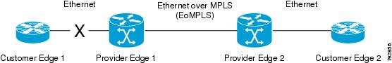
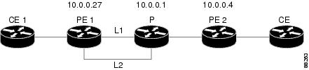
 Feedback