Overview

Cisco Catalyst Wireless Gateways extend an enterprise network to remote workers, providing numerous advantages:

  • Hardware-based stable connectivity to an enterprise VPN

  • Optimized network performance with Wi-Fi 6

  • Cellular network connectivity, in supporting models, providing a cellular internet connection (with one active and one standby SIM) for uninterrupted internet connectivity

  • Separate service set identifiers (SSIDs) for connecting work and personal devices

Cisco Catalyst Wireless Gateway connectivity is as follows:

  • The Cisco Catalyst Wireless Gateway CG113-W6 accesses the internet using a wired WAN connection at a remote site.

  • The Cisco Catalyst Wireless Gateway CG113-4GW6 accesses the internet using a wired WAN connection at a remote site or using a cellular link. The device supports two SIM cards: one active, and one on standby. If the wired WAN connection fails, the device fails over to the cellular link to ensure internet connectivity.


Note


The device has a single cellular connection, so only one SIM can be active at a given time. You can configure which of the two SIM slots serves as primary and which serves as secondary (failover).


Managing Cisco Catalyst Wireless Gateways

Use Cisco SD-WAN Manager to configure and manage Cisco Catalyst Wireless Gateways. Cisco SD-WAN Manager provides a convenient workflow for configuring Wi-Fi, cellular, VPN, and other functionality. Cisco SD-WAN Manager also provides methods for monitoring device performance.

Cisco Catalyst Wireless Gateway CG113-W6

The following sections provide hardware specifications and other information about the Cisco Catalyst Wireless Gateway CG113-W6.

Package Contents

The package for this device contains the following:

  • Device chassis

  • Power supply

  • Pointer card, providing a link to the product documentation

Hardware Specifications

Table 1. Hardware Specifications, Cisco Catalyst Wireless Gateway CG113-W6

Item

Specifications

Interfaces

2.5 Gigabit ethernet

1

1 Gigabit ethernet

2

Wi-Fi

Wi-Fi bands

2.4 GHz, 5 GHz

Antennas

Dual 2x2 MIMO (internal)

Cellular

None

Operating Conditions

Temperature

0℃ to 45℃ (32℉ to 113℉)

Humidity

10 to 90% RH Non-condensing

Altitude

3000 m (10,000 ft)

Storage Conditions

Temperature

-25℃ to 70℃ (-13℉ to 158℉)

Humidity

5 to 95% RH Non-condensing

Altitude

4570 m (15,000 ft)

Power

Power adapter

12V, 3A maximum

Models, according to region: CG113-4G-PWR-US, -EU, -AU

Power connector

USB-C

Mounting and Accessories

The device is installed on a desk or other flat surface. No additional mounting equipment is supplied.

Ethernet Interfaces, Power Port, and Reset Button

The ethernet interfaces, power port, and reset button are located on the back panel of the device.
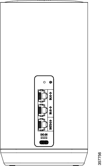
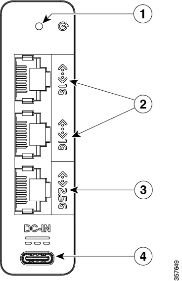
Figure 1. Back Panel
Figure 2. Reset Button, Interfaces, and Power Port

1

Reset button

2

1 Gbps ethernet interfaces

3

2.5 Gbps ethernet interface

4

USB-C power port

LED Indicators

The single LED indicator appears on the front panel of the device.
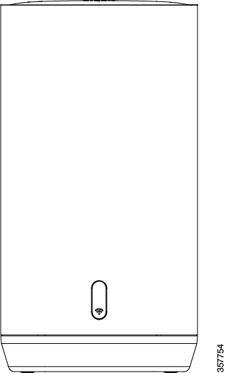
Figure 3. Front Panel
Figure 4. LED Indicator on Front Panel

1

LED indicator for Wi-Fi connectivity

Table 2. LED Indicator Behavior

LED

Color

Description

Wi-Fi

Red, blinking

Device is booting

Red, solid

Wi-Fi not ready

Green, solid

Wi-Fi ready, no devices connected

Blue, solid

Wi-Fi ready, one or more devices connected

Antenna Information

Antennas, Gain, and Impedance

Table 3. List of Internal Antennas Supported on Cisco CG113-W6

Antenna Type

Antenna Gain

Antenna Impedance

Antenna type: Wi-Fi

Single-Port/Dual Band/Omni-directional

(Linear Polarization, Wi-Fi 1)

2.4GHz: 4dBi

5GHz: 5dBi

50 ohms

Antenna type: Wi-Fi

Single-Port/Dual Band/Omni-directional

(Linear Polarization, Wi-Fi 2)

2.4GHz: 2.6dBi


5GHz: 4.8dBi

50 ohms

Maximum Transmitted Power

The frequency and the maximum transmitted power are listed below:

2412-2472MHz: 19.99 dBm

5180-5240MHz: 22.92 dBm

5260-5320MHz: 22.95 dBm

5500-5700: 29.97 dBm

Power Supply

The following power supplies are included with the device, depending on region.

Table 4. Power Supply Part and Model Numbers, by Region

Region

Cisco Part Number

Model Number

USA

CG113-4G-PWR-US

ADH-36DW B

Australia

CG113-4G-PWR-AU

ADH-36DW E

EU, UK

CG113-4G-PWR-EU

ADH-36DW C

Table 5. Power Supply Specifications

Specification

Description

Input

100-240V AC 50-60Hz

Cisco Catalyst Wireless Gateway CG113-4GW6

The following sections provide hardware specifications and other information about the Cisco Catalyst Wireless Gateway CG113-4GW6.

Package Contents

The package for this device contains the following:

  • Device chassis

  • Power supply

  • Pointer card, providing a link to the product documentation

Hardware Specifications

Table 6. Hardware Specifications, Cisco Catalyst Wireless Gateway CG113-4GW6

Item

Specifications

Interfaces

2.5 Gigabit ethernet

1

1 Gigabit ethernet

2

Wi-Fi

Wi-Fi bands

2.4 GHz, 5 GHz

Antennas

Dual 2x2 MIMO (internal)

Cellular

SIM slots

2

Cellular bands

4G/Cat7

Operating Conditions

Temperature

0℃ to 45℃ (32℉ to 113℉)

Humidity

10 to 90% RH Non-condensing

Altitude

3000 m (10,000 ft)

Storage Conditions

Temperature

-25℃ to 70℃ (-13℉ to 158℉)

Humidity

5 to 95% RH Non-condensing

Altitude

4570 m (15,000 ft)

Power

Power adapter

12V, 3A maximum

Models, according to region: CG113-4G-PWR-US, -EU, -AU

Power connector

USB-C

Mounting and Accessories

The device is installed on a desk or other flat surface. No additional mounting equipment is supplied.

Ethernet Interfaces and Power Port

The ethernet interfaces, power port, and reset button are located on the back panel of the device.

Figure 5. Back Panel
Figure 6. Reset Button, Interfaces, and Power Port

1

Reset button

2

1 Gbps ethernet interfaces

3

2.5 Gbps ethernet interface

4

USB-C power port

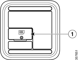
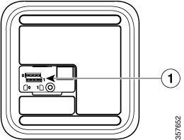
SIM Card Slots

The SIM card slots are accessible from the bottom panel of the device. For information about installing SIM cards, see Install SIMs, LTE Models.

Figure 7. Bottom Panel

1

Cover for SIM card slots

Figure 8. SIM Card Slots, with the Cover Removed

1

SIM card slots 0 and 1

Figure 9. SIM Card Slots

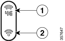
LED Indicators

The LED indicators appear on the front panel of the device.

Figure 10. Front Panel
Figure 11. LED Indicators on Front Panel

1

LED indicator for cellular connectivity

2

LED indicator for Wi-Fi connectivity

Table 7. LED Indicator Behavior

LED

Color

Description

Wi-Fi

Red, blinking

Device is booting

Red, solid

Wi-Fi not ready

Green, solid

Wi-Fi ready, no devices connected

Blue, solid

Wi-Fi ready, one or more devices connected

Green, blinking

Firmware upgrade in progress

4G

Red, blinking

Device is booting

Red, solid

Completed boot, no SIM detected, not connected to network

Green, solid

SIM detected, connected to network, wired connection is active and cellular connection is standby

Green, blinking

Firmware upgrade in progress

Blue, blinking

SIM detected, connected to network, cellular connection is active, weak signal

Blue, solid

SIM detected, connected to network, cellular connection is active, strong signal

Antenna Information

Antennas, Gain, and Impedance

Table 8. List of Internal Antennas Supported on Cisco CG113-4GW6 (Includes LTE)

Antenna Type

Antenna Gain

Antenna Impedance

Antenna type: Wi-Fi

Single-Port/Dual Band/Omni-directional

(Linear Polarization, Wi-Fi 1)

2.4GHz: 4dBi

5GHz: 5dBi

50 ohms

Antenna type: Wi-Fi

Single-Port/Dual Band/Omni-directional

(Linear Polarization, Wi-Fi 2)

2.4GHz: 2.6dBi


5GHz: 4.8dBi

50 ohms

Antenna type: LTE

Single-Port/LTE Full Band/Omni-directional

(Mixed Polarization, LTE Main)

617-960MHz: 2.1dBi


1710-2700MHz: 4.1dBi


3300-3800MHz: 3.6dBi

50 ohms

Antenna type: LTE

Single-Port/LTE Full Band/Omni-directional

(Vertical Polarization, LTE Auxiliary)

617-960MHz: 2.1dBi


1710-2700MHz: 4.1dBi


3300-3800MHz: 3.6dBi

50 ohms

Maximum Transmitted Power

The frequency and the maximum transmitted power are listed below:

2412-2472MHz: 19.99 dBm

5180-5240MHz: 22.92 dBm

5260-5320MHz: 22.95 dBm

5500-5700: 29.97 dBm

Power Supply

The following power supplies are included with the device, depending on region.

Table 9. Power Supply Part and Model Numbers, by Region

Region

Cisco Part Number

Model Number

USA

CG113-4G-PWR-US

ADH-36DW B

Australia

CG113-4G-PWR-AU

ADH-36DW E

EU, UK

CG113-4G-PWR-EU

ADH-36DW C

Table 10. Power Supply Specifications

Specification

Description

Input

100-240V AC 50-60Hz