Overview of Cisco IoT Field Network Director
This section provides an overview of the Cisco IoT Field Network Director (Cisco IoT FND) and describes its role within the Cisco Internet of Things (IoT) Network solution. Topics include:
■![]() Cisco IoT Connected Grid Network
Cisco IoT Connected Grid Network
Cisco IoT Connected Grid Network
This section provides an overview of:
■![]() Cisco IoT FND Features and Capabilities
Cisco IoT FND Features and Capabilities
The Cisco IoT Field Network Director (IoT FND) is a software platform that manages a multi-service network and security infrastructure for IoT applications, such as smart grid applications, including Advanced Metering Infrastructure (AMI), Distribution Automation (DA), distributed intelligence, and substation automation. IoT FND is a scalable, highly-secure, modular, and open platform with an extensible architecture. IoT FND is a multi-vendor, multi-service, communications network management platform that enables network connectivity to an open ecosystem of power grid devices.
IoT FND is built on a layered system architecture to enable clear separation between network management functionality and applications, such as a distribution management system (DMS), outage management system (OMS), and meter data management (MDM). This clear separation between network management and applications helps utilities roll out Smart Grid projects incrementally, for example with AMI, and extend into distribution automation using a shared, multi-service network infrastructure and a common, network management system across various utility operations.
■![]() Geographic Information System (GIS) map-based, visualization, monitoring, troubleshooting, and alarm notifications
Geographic Information System (GIS) map-based, visualization, monitoring, troubleshooting, and alarm notifications
■![]() Group-based configuration management for routers and smart meter endpoints
Group-based configuration management for routers and smart meter endpoints
■![]() OS compatible (Cisco IOS, Guest OS, IOx) and provides application management
OS compatible (Cisco IOS, Guest OS, IOx) and provides application management
■![]() Rule-engine infrastructure for customizable threshold-based alarm processing and event generation
Rule-engine infrastructure for customizable threshold-based alarm processing and event generation
■![]() North Bound API for transparent integration with utility head-end and operational systems
North Bound API for transparent integration with utility head-end and operational systems
■![]() High availability and disaster recovery
High availability and disaster recovery
Cisco IoT FND provides powerful Geographic Information System (GIS) visualization and monitoring capability. Through the browser-based interface, utility operators manage and monitor devices in a Cisco IoT Connected Grid Field Area Network (FAN) solution, using IPv6 over Low-power Wireless Personal Area Networks (6LoWPANs). The FAN includes the following devices:
■![]() Cisco 1000 Series Connected Grid Routers (CGRs), also called pole-top or DIN-rail-mount routers. These devices are referred to as routers in this document and identified by model (for example, CGR1000, CGR1120, or CGR1240) on the Field Devices page. Available CGR modules provide 3G, 4G LTE, and mesh connectivity (WPAN). CGR1000s also support the Itron OpenWay RIVA CAM module, which provides connectivity to the Itron OpenWay RIVA electric and gas-water devices.
Cisco 1000 Series Connected Grid Routers (CGRs), also called pole-top or DIN-rail-mount routers. These devices are referred to as routers in this document and identified by model (for example, CGR1000, CGR1120, or CGR1240) on the Field Devices page. Available CGR modules provide 3G, 4G LTE, and mesh connectivity (WPAN). CGR1000s also support the Itron OpenWay RIVA CAM module, which provides connectivity to the Itron OpenWay RIVA electric and gas-water devices.
■![]() Cisco 800 Series Integrated Services Routers (ISR 800s) are used in most networks as edge routers or gateways to provide WAN connectivity (cellular, satellite over Ethernet, and WiFi) to an end device (energy-distribution automation devices, other verticals such as ATMs, and mobile deployments such as taxis or trucks). These devices are referred to as routers in this document; and identified by product ID (for example, C800 or C819) on the Field Devices page. You can use IoT FND to manage the following hardened Cisco 819H ISRs:
Cisco 800 Series Integrated Services Routers (ISR 800s) are used in most networks as edge routers or gateways to provide WAN connectivity (cellular, satellite over Ethernet, and WiFi) to an end device (energy-distribution automation devices, other verticals such as ATMs, and mobile deployments such as taxis or trucks). These devices are referred to as routers in this document; and identified by product ID (for example, C800 or C819) on the Field Devices page. You can use IoT FND to manage the following hardened Cisco 819H ISRs:
IoT FND also manages the following non-hardened Cisco 819 ISRs:
■![]() Cisco 4000 Series Integrated Services Routers (ISR 4300 and ISR4400) consolidate many must-have IT functions in a single platform, such as network, security, compute, storage, and unified communications to help you build out the digital capabilities in your enterprise branch offices. The platform is modular and upgradeable, so you can add new services without changing equipment.
Cisco 4000 Series Integrated Services Routers (ISR 4300 and ISR4400) consolidate many must-have IT functions in a single platform, such as network, security, compute, storage, and unified communications to help you build out the digital capabilities in your enterprise branch offices. The platform is modular and upgradeable, so you can add new services without changing equipment.
■![]() Cisco 800 Series Industrial Integrated Services Routers (IR800s) are compact, ruggedized, Cisco IOS Software routers. They offer support for integrated 4G LTE wireless WAN (IR807, IR809 and IR829 models) and wireless LAN capabilities (IR829 only). These devices are referred to as routers in this document; and identified by product ID (for example, IR800) on the Field Devices page. You can use IoT FND to manage the following IR800 models:
Cisco 800 Series Industrial Integrated Services Routers (IR800s) are compact, ruggedized, Cisco IOS Software routers. They offer support for integrated 4G LTE wireless WAN (IR807, IR809 and IR829 models) and wireless LAN capabilities (IR829 only). These devices are referred to as routers in this document; and identified by product ID (for example, IR800) on the Field Devices page. You can use IoT FND to manage the following IR800 models:
–![]() IR807: Highly compact, low-power industrial router. Well-suited for industrial applications (distribution automation for utilities, transportation, manufacturing) and remote asset management across the extended enterprise.
IR807: Highly compact, low-power industrial router. Well-suited for industrial applications (distribution automation for utilities, transportation, manufacturing) and remote asset management across the extended enterprise.
–![]() IR809: Very compact, cellular (3G,4G/LTE) industrial routers that enable reliable and secure cellular connectivity for remote asset monitoring and machine-to-machine (M2M) applications such as distribution automation, pipeline monitoring and roadside infrastructure monitoring.
IR809: Very compact, cellular (3G,4G/LTE) industrial routers that enable reliable and secure cellular connectivity for remote asset monitoring and machine-to-machine (M2M) applications such as distribution automation, pipeline monitoring and roadside infrastructure monitoring.
–![]() IR829: Highly ruggedized compact cellular (3G and 4G LTE with GPS and dual SIM) and WLAN (2.4/5GHz) industrial routers supporting scalable, reliable and secure management of those IoT applications requiring mobile connectivity such as fleet vehicles and mass transit.
IR829: Highly ruggedized compact cellular (3G and 4G LTE with GPS and dual SIM) and WLAN (2.4/5GHz) industrial routers supporting scalable, reliable and secure management of those IoT applications requiring mobile connectivity such as fleet vehicles and mass transit.
■![]() Cisco 5921 Embedded Services Router (ESR) is designed to operate on small, low-power, Linux-based platforms. It helps integration partners extend the use of Cisco IOS into extremely mobile and portable communications systems. It also provides highly secure data, voice, and video communications to stationary and mobile network nodes across wired and wireless links.
Cisco 5921 Embedded Services Router (ESR) is designed to operate on small, low-power, Linux-based platforms. It helps integration partners extend the use of Cisco IOS into extremely mobile and portable communications systems. It also provides highly secure data, voice, and video communications to stationary and mobile network nodes across wired and wireless links.
■![]() The Cisco Wireless Gateway for LoRaWAN (IXM-LPWA-800, IXM-LPWA-900) can be a standalone product that connects to Ethernet switches or routers or connects to LAN ports of the Cisco 800 Series Industrial Integrated Services Routers. This product can be configured as a radio interface of the Cisco Industrial Routers 809 and 829. One or multiple gateways are connected to the LAN port(s) of the IR809 or IR829 via Ethernet or VLANs with encrypted links. Through this configuration, it provides LoRaWAN radio access while the IR809 or IR829 offer backhaul support for Gigabit Ethernet (electrical or fiber), 4G/LTE, or Wi-Fi.
The Cisco Wireless Gateway for LoRaWAN (IXM-LPWA-800, IXM-LPWA-900) can be a standalone product that connects to Ethernet switches or routers or connects to LAN ports of the Cisco 800 Series Industrial Integrated Services Routers. This product can be configured as a radio interface of the Cisco Industrial Routers 809 and 829. One or multiple gateways are connected to the LAN port(s) of the IR809 or IR829 via Ethernet or VLANs with encrypted links. Through this configuration, it provides LoRaWAN radio access while the IR809 or IR829 offer backhaul support for Gigabit Ethernet (electrical or fiber), 4G/LTE, or Wi-Fi.
■![]() Cisco Interface Module for Long Range Wide Area Network (LoRAWAN) is an extension module for the industrial routers, Cisco IR809 and IR829, and serves as a carrier-grade gateway for outdoor deployments. The module provides unlicensed low-power wide area (LPWA) wireless connectivity for a range of Internet of Things (IoT) use cases such as asset tracking, water and gas metering, street lighting, smart parking/building/agriculture, and environment monitoring. There are two models supported, which are differentiated by their band support (863-870 MHz ISM or 902-928 MHz ISM). The module is identified by product ID (for example, IXM-LORA-800-H-V2).
Cisco Interface Module for Long Range Wide Area Network (LoRAWAN) is an extension module for the industrial routers, Cisco IR809 and IR829, and serves as a carrier-grade gateway for outdoor deployments. The module provides unlicensed low-power wide area (LPWA) wireless connectivity for a range of Internet of Things (IoT) use cases such as asset tracking, water and gas metering, street lighting, smart parking/building/agriculture, and environment monitoring. There are two models supported, which are differentiated by their band support (863-870 MHz ISM or 902-928 MHz ISM). The module is identified by product ID (for example, IXM-LORA-800-H-V2).
■![]() Cisco 500 Series Wireless Personal Area Network (WPAN) Industrial Routers (IR500) supply RF mesh connectivity to IPv4 and serial IoT devices (for example, recloser control, cap bank control, voltage regulator controls, and other remote terminal units).
Cisco 500 Series Wireless Personal Area Network (WPAN) Industrial Routers (IR500) supply RF mesh connectivity to IPv4 and serial IoT devices (for example, recloser control, cap bank control, voltage regulator controls, and other remote terminal units).
Note: CGRs, C800s, IR800s, IR500s and other types of mesh endpoint devices can coexist on a network, but cannot be in the same device group (see Creating Device Groups and Working with Mesh Endpoint Firmware Images) or firmware management group (see Configuring Firmware Group Settings).
■![]() Cisco 800 Series Access Points are integrated with IR800s and C800s. These devices are referred to as routers in this document; and identified by product ID (for example, AP800). You can use IoT FND to manage the following AP800 models:
Cisco 800 Series Access Points are integrated with IR800s and C800s. These devices are referred to as routers in this document; and identified by product ID (for example, AP800). You can use IoT FND to manage the following AP800 models:
■![]() Cisco ASR 1000 Series Aggregation Services Routers (ASRs), Cisco ISR 3900 Series Integrated Service Routers (ISRs), and ISR 4300 and ISR 4400 routers are referred to as head-end routers or HERs in this document.
Cisco ASR 1000 Series Aggregation Services Routers (ASRs), Cisco ISR 3900 Series Integrated Service Routers (ISRs), and ISR 4300 and ISR 4400 routers are referred to as head-end routers or HERs in this document.
■![]() Cisco IPv6 RF (radio frequency), PLC (power line communications), and Dual PHY (RF and PLC) mesh endpoints (smart meters and range extenders).
Cisco IPv6 RF (radio frequency), PLC (power line communications), and Dual PHY (RF and PLC) mesh endpoints (smart meters and range extenders).
Note: In this document, mesh endpoints refers to Cisco range extenders and Cisco-compatible smart meters.
IoT FND typically resides in the utility control center with other utility head-end operational systems, such as an AMI head end, distribution management system, or outage management system. IoT FND features enterprise-class fault, configuration, accounting, performance, and security (FCAPS) functionality, as defined in the Open Systems Interconnection (OSI) model.
The Cisco IoT FND North Bound Application Programmable Interface (NB API) allows various utility applications like DMS, OMS, or MDM to pull appropriate, service-specific data for distribution grid information, outage information, and metering data from a shared, multi-server communication network infrastructure. For more information about the Cisco IoT FND North Bound API, see the Cisco IoT FND NMS North Bound API Programming Guide for your IoT FND installation.
The NB API can send events using HTTPS. NB API clients must subscribe to IoT FND by providing a valid HTTPS URL to send events. IoT FND accepts all SSL and handshake certificates published by the NB API client (the event consumer) while making the secure connection.
Cisco IoT FND Features and Capabilities
■![]() Configuration Management – Cisco IoT FND facilitates configuration of a large number of Cisco CGRs, Cisco C800s, Cisco ISRs, Cisco IRs, Cisco ASRs, and mesh endpoints. Use Cisco IoT FND to bulk-configure devices by placing them into configuration groups, editing settings in a configuration template, and then pushing the configuration to all devices in the group.
Configuration Management – Cisco IoT FND facilitates configuration of a large number of Cisco CGRs, Cisco C800s, Cisco ISRs, Cisco IRs, Cisco ASRs, and mesh endpoints. Use Cisco IoT FND to bulk-configure devices by placing them into configuration groups, editing settings in a configuration template, and then pushing the configuration to all devices in the group.
■![]() Device and Event Monitoring – Cisco IoT FND displays easy-to-read tabular views of extensive information generated by devices, allowing you to monitor your network for errors. Cisco IoT FND provides integrated Geographic Information System (GIS) map-based visualization of FAN devices such as routers and smart meters. Use IoT FND to create CGR-specific work orders that include the required certificates to access the router.
Device and Event Monitoring – Cisco IoT FND displays easy-to-read tabular views of extensive information generated by devices, allowing you to monitor your network for errors. Cisco IoT FND provides integrated Geographic Information System (GIS) map-based visualization of FAN devices such as routers and smart meters. Use IoT FND to create CGR-specific work orders that include the required certificates to access the router.
■![]() Firmware Management – Cisco IoT FND serves as a repository for Cisco CGR, Cisco C800, Cisco ISR, Cisco IR, and mesh endpoint firmware images. Use Cisco IoT FND to upgrade the firmware running on groups of devices by loading the firmware image file onto the Cisco IoT FND server, and then uploading the image to the devices in the group. Once uploaded, use IoT FND to install the firmware image directly on the devices. In release 3.0.1-36 and later, a Subnet List view on the Firmware Upgrade page for Mesh Endpoints lets you filter and view subnets by PAN identifier (PAN ID) and Group (details include number of nodes within a group, hops away from the router and operational status). A subnet progress histogram has also been added.
Firmware Management – Cisco IoT FND serves as a repository for Cisco CGR, Cisco C800, Cisco ISR, Cisco IR, and mesh endpoint firmware images. Use Cisco IoT FND to upgrade the firmware running on groups of devices by loading the firmware image file onto the Cisco IoT FND server, and then uploading the image to the devices in the group. Once uploaded, use IoT FND to install the firmware image directly on the devices. In release 3.0.1-36 and later, a Subnet List view on the Firmware Upgrade page for Mesh Endpoints lets you filter and view subnets by PAN identifier (PAN ID) and Group (details include number of nodes within a group, hops away from the router and operational status). A subnet progress histogram has also been added.
■![]() OS Migration – For Cisco CGR 1000, IoT FND allows you to migrate CGRs running CG-OS to IOS.
OS Migration – For Cisco CGR 1000, IoT FND allows you to migrate CGRs running CG-OS to IOS.
■![]() Zero Touch Deployment – This ease-of-use feature automatically registers (enrolls) and distributes X.509 certificates and provisioning information over secure connections within a connected grid network.
Zero Touch Deployment – This ease-of-use feature automatically registers (enrolls) and distributes X.509 certificates and provisioning information over secure connections within a connected grid network.
■![]() Tunnel Provisioning – Protects data exchanged between Cisco ASRs and Cisco CGRs, C800s, Cisco ISRs and Cisco IRs, and prevents unauthorized access to Cisco CGRs, to provide secure communication between devices. Cisco IoT FND can execute CLI commands to provision secure tunnels between Cisco CGRs, C800s, Cisco ISRs and Cisco IRs and Cisco ASRs. Use IoT FND to bulk-configure tunnel provisioning using groups.
Tunnel Provisioning – Protects data exchanged between Cisco ASRs and Cisco CGRs, C800s, Cisco ISRs and Cisco IRs, and prevents unauthorized access to Cisco CGRs, to provide secure communication between devices. Cisco IoT FND can execute CLI commands to provision secure tunnels between Cisco CGRs, C800s, Cisco ISRs and Cisco IRs and Cisco ASRs. Use IoT FND to bulk-configure tunnel provisioning using groups.
■![]() IPv6 RPL Tree Polling – The IPv6 Routing Protocol for Low-power and Lossy Networks (RPL) finds its neighbors and establishes routes using ICMPv6 message exchanges. RPL manages routes based on the relative position of the mesh endpoints to the CGR that is the root of the routing tree. RPL tree polling is available through the mesh nodes and CGR periodic updates. The RPL tree represents the mesh topology, which is useful for troubleshooting. For example, the hop count information received from the RPL tree can determine the use of unicast or multicast for the firmware download process. IoT FND maintains a periodically updated snapshot of the RPL tree.
IPv6 RPL Tree Polling – The IPv6 Routing Protocol for Low-power and Lossy Networks (RPL) finds its neighbors and establishes routes using ICMPv6 message exchanges. RPL manages routes based on the relative position of the mesh endpoints to the CGR that is the root of the routing tree. RPL tree polling is available through the mesh nodes and CGR periodic updates. The RPL tree represents the mesh topology, which is useful for troubleshooting. For example, the hop count information received from the RPL tree can determine the use of unicast or multicast for the firmware download process. IoT FND maintains a periodically updated snapshot of the RPL tree.
■![]() Dynamic Multipoint VPN and FlexVPN - For Cisco C800 devices and Cisco IR800 devices, DMVPN and FlexVPN do not require IoT FND to apply device-specific tunnel configuration to the HER during tunnel provisioning. HER tunnel provisioning is only required for site-to-site VPN tunnels.
Dynamic Multipoint VPN and FlexVPN - For Cisco C800 devices and Cisco IR800 devices, DMVPN and FlexVPN do not require IoT FND to apply device-specific tunnel configuration to the HER during tunnel provisioning. HER tunnel provisioning is only required for site-to-site VPN tunnels.
■![]() Embedded Access Point (AP) Management - IoT FND provides management of embedded APs on C819 and IR829 routers.
Embedded Access Point (AP) Management - IoT FND provides management of embedded APs on C819 and IR829 routers.
■![]() Dual PHY Support – IoT FND can communicate with devices that support Dual PHY (RF and PLC) traffic. IoT FND identifies CGRs running Dual PHY, enables configuration to masters and slaves, and collects metrics from masters. IoT FND also manages security keys for Dual PHY CGRs. On the mesh side, IoT FND identifies Dual PHY nodes using unique hardware IDs, enables configuration pushes and firmware updates, and collects metrics, including RF and PLC traffic ratios.
Dual PHY Support – IoT FND can communicate with devices that support Dual PHY (RF and PLC) traffic. IoT FND identifies CGRs running Dual PHY, enables configuration to masters and slaves, and collects metrics from masters. IoT FND also manages security keys for Dual PHY CGRs. On the mesh side, IoT FND identifies Dual PHY nodes using unique hardware IDs, enables configuration pushes and firmware updates, and collects metrics, including RF and PLC traffic ratios.
■![]() Guest OS (GOS) Support – For Cisco IOS CGR 1000 and IR800 devices that support Guest OS, IoT FND allows approved users to manage applications running on the supported operating systems. IoT FND supports all phases of application deployment, and displays application status and the Hypervisor version running on the device.
Guest OS (GOS) Support – For Cisco IOS CGR 1000 and IR800 devices that support Guest OS, IoT FND allows approved users to manage applications running on the supported operating systems. IoT FND supports all phases of application deployment, and displays application status and the Hypervisor version running on the device.
■![]() Device Location Tracking – For CGR 1000, C800, and IR800 devices, IoT FND displays real-time location and device location history. This feature requires enabling the GPS feature.
Device Location Tracking – For CGR 1000, C800, and IR800 devices, IoT FND displays real-time location and device location history. This feature requires enabling the GPS feature.
■![]() Software Security Module (SSM) – This is a low-cost alternative to the Hardware Security Module (HSM), and is used for signing CSMP messages sent to meters and IR500 devices.
Software Security Module (SSM) – This is a low-cost alternative to the Hardware Security Module (HSM), and is used for signing CSMP messages sent to meters and IR500 devices.
■![]() Customer Certificates – Cisco IoT FND allows you to use your own CA and ECC-based certificates to sign smart meter messages.
Customer Certificates – Cisco IoT FND allows you to use your own CA and ECC-based certificates to sign smart meter messages.
■![]() Diagnostics and Troubleshooting – The IoT FND rule engine infrastructure provides effective monitoring of triage-based troubleshooting. Device troubleshooting runs on-demand device path trace and ping on any CGR 1000, IR800, Cisco Series Integrated Services Routers (C800), Cisco 5921 Embedded Services Router (C5921), range extender, gateway or meter (mesh endpoints).
Diagnostics and Troubleshooting – The IoT FND rule engine infrastructure provides effective monitoring of triage-based troubleshooting. Device troubleshooting runs on-demand device path trace and ping on any CGR 1000, IR800, Cisco Series Integrated Services Routers (C800), Cisco 5921 Embedded Services Router (C5921), range extender, gateway or meter (mesh endpoints).
■![]() High Availability – To ensure uninterrupted network management and monitoring, you can deploy the Cisco IoT FND solution in a High Availability (HA) configuration. By using clusters of load-balanced IoT FND servers and primary and standby IoT FND databases, Cisco IoT FND constantly monitors the health of the system, including connectivity within clusters and server resource usage. If a server cluster member or database becomes unavailable or a tunnel fails, another takes its place seamlessly. Additionally, you can add reliability to your IoT FND solution by configuring redundant tunnels between a Cisco CGR and multiple Cisco ASRs.
High Availability – To ensure uninterrupted network management and monitoring, you can deploy the Cisco IoT FND solution in a High Availability (HA) configuration. By using clusters of load-balanced IoT FND servers and primary and standby IoT FND databases, Cisco IoT FND constantly monitors the health of the system, including connectivity within clusters and server resource usage. If a server cluster member or database becomes unavailable or a tunnel fails, another takes its place seamlessly. Additionally, you can add reliability to your IoT FND solution by configuring redundant tunnels between a Cisco CGR and multiple Cisco ASRs.
■![]() Power Outage Notifications – Connected Grid Endpoints (CGEs) implement a power outage notification service to support timely and efficient reporting of power outages. In the event of a power outage, CGEs perform the necessary functions to conserve energy and notify neighboring nodes of the outage. Routers relay the power outage notification to IoT FND, which then issues push notifications to customers to relate information on the outage.
Power Outage Notifications – Connected Grid Endpoints (CGEs) implement a power outage notification service to support timely and efficient reporting of power outages. In the event of a power outage, CGEs perform the necessary functions to conserve energy and notify neighboring nodes of the outage. Routers relay the power outage notification to IoT FND, which then issues push notifications to customers to relate information on the outage.
■![]() Mesh Upgrade Support – Over-the-air software and firmware upgrades to field devices such as Cisco CGRs and CGEs (for example, AMI meter endpoints).
Mesh Upgrade Support – Over-the-air software and firmware upgrades to field devices such as Cisco CGRs and CGEs (for example, AMI meter endpoints).
■![]() Audit Logging – Logs access information for user activity for audit, regulatory compliance, and Security Event and Incident Management (SEIM) integration. This simplifies management and enhances compliance by integrated monitoring, reporting, and troubleshooting capabilities.
Audit Logging – Logs access information for user activity for audit, regulatory compliance, and Security Event and Incident Management (SEIM) integration. This simplifies management and enhances compliance by integrated monitoring, reporting, and troubleshooting capabilities.
■![]() North Bound APIs – Eases integration of existing utility applications such as outage management system (OMS), meter data management (MDM), trouble-ticketing systems, and manager-of-managers.
North Bound APIs – Eases integration of existing utility applications such as outage management system (OMS), meter data management (MDM), trouble-ticketing systems, and manager-of-managers.
■![]() Work Orders for Device Manager – Credentialed field technicians can remotely access and update work orders.
Work Orders for Device Manager – Credentialed field technicians can remotely access and update work orders.
■![]() Role – Based Access Controls – Integrates with enterprise security policies and role-based access control for AMI network devices.
Role – Based Access Controls – Integrates with enterprise security policies and role-based access control for AMI network devices.
■![]() Event and Issue Management – Fault event collection, filtering, and correlation for communication network monitoring. IoT FND supports a variety of fault-event mechanisms for threshold-based rule processing, custom alarm generation, and alarm event processing. Faults display on a color-coded GIS-map view for various endpoints in the utility network. This allows operator-level custom fault-event generation, processing, and forwarding to various utility applications such as an outage management system. Automatic issue tracking is based on the events collected.
Event and Issue Management – Fault event collection, filtering, and correlation for communication network monitoring. IoT FND supports a variety of fault-event mechanisms for threshold-based rule processing, custom alarm generation, and alarm event processing. Faults display on a color-coded GIS-map view for various endpoints in the utility network. This allows operator-level custom fault-event generation, processing, and forwarding to various utility applications such as an outage management system. Automatic issue tracking is based on the events collected.
IoT FND Architecture
Zero Touch Deployment Architecture provides a high-level view of the systems and communication paths that exist in a typical utility company operating on a Cisco CGR connected grid network in which Zero Touch Deployment is in use.
For Cisco IOS CGRs, we recommend a tunnel configuration using FlexVPN.
For Cisco C800s and IR800s, we recommend using Dynamic Multipoint VPN (DMVPN) or FlexVPN.
Figure 1 Zero Touch Deployment Architecture

In this example, the firewall provides separation between those items in the utility company public network (DMZ) and its private network.
The utility company private network shows systems that might reside behind the firewall such as the Cisco IoT FND, the Oracle database server, the Cisco IoT FND North Bound API, the DHCP server, and the Certificate Authority (CA). The Cisco IoT FND Tunnel Provisioning Server proxy (TPS proxy) and Registration Authority (RA) might be located in the DMZ.
After installing and powering on the Cisco CGR, it becomes active in the network and registers its certificate with the RA by employing the Simple Certificate Enrollment Protocol (SCEP). The RA ( Cisco 3945 ISR in Zero Touch Deployment Architecture), functioning as a CA proxy, obtains certificates for the Cisco CGR from the CA. The Cisco CGR then sends a tunnel provisioning request over HTTPS to the TPS proxy that forwards it to IoT FND.
Cisco IoT FND manages collection of all information necessary to configure a tunnel between Cisco CGRs and the head-end router ( Cisco ASR 1001 in Zero Touch Deployment Architecture). For CG-OS CGR installations, we recommend a network configuration with an outer IPsec tunnel over IPv4 inside which is an IPv6-in-IPv4 GRE tunnel. All traffic from the MEs is over IPv6. The GRE tunnel provides a path for IPv6 traffic to reach the data center. The outer IPsec tunnel secures that traffic. When the tunnel is active, the Cisco CGR (after configuration) connects to the utility company network like a Virtual Private Network (VPN).
Main Components of a IoT FND Solution
|
|
|
|---|---|
This the heart of IoT FND deployments. It runs on an RHEL server and allows administrators to control different aspects of the IoT FND deployment using its browser-based graphical user interface. IoT FND HA deployments include two or more IoT FND servers connected to a load balancer. |
|
This Oracle database stores all information managed by your IoT FND solution, including all metrics received from the MEs and all device properties such as firmware images, configuration templates, logs, event information, and so on. |
|
This is a low-cost alternative to the Hardware Security Module (HSM), and is used for signing CSMP messages sent to meters and IR500 devices. |
|
Allows routers to communicate with IoT FND when they first start up in the field. After IoT FND provisions tunnels between the routers and ASRs, the routers communicate with IoT FND directly. |
|
(Optional) IoT FND uses the Cisco ACE 4710 in Zero Touch Deployment Architecture to provide HA. The load balancer distributes the traffic among the IoT FND servers in the server cluster in your solution. |
High Availability and Tunnel Redundancy
The example in Zero Touch Deployment Architecture is of a single-server deployment with one database and no tunnel redundancy. However, you could take advantage of Cisco IoT FND HA support to deploy a cluster of Cisco IoT FND servers connected to a Cisco ACE 4710 load balancer, as shown in IoT FND Server and Database HA. The load balancer sends requests to the servers in a round-robin fashion. If a server fails, the load balancer keeps servicing requests by sending them to the other servers in the cluster.
You could also deploy a standby Cisco IoT FND database to provide another layer of high availability in the system with minimal data loss.
Figure 2 IoT FND Server and Database HA

To provide tunnel redundancy, IoT FND allows you to create multiple tunnels to connect a CGR to multiple ASRs, as shown in IoT FND Tunnel Redundancy.
Figure 3 IoT FND Tunnel Redundancy

For more information about HA, see Database High Availability.
Mesh Endpoints
The Cisco Field Area Network (FAN) solution brings the first multi-service communications infrastructure to the utility field area network. It delivers applications such as AMI, DA, and Protection and Control over a common network platform.
Advanced meter deployments follow a structured process designed to match the right solution to the needs of the utility company. This process moves in phases that require coordination between metering, IT, operations, and engineering. The first phase for most utilities is identification of goals, followed by analysis of data needs, and business processes. After an evaluation of the business case is complete and a technology chosen, system implementation and validation complete the process.
Once the utility company moves past the business case into system implementation, unforeseen complications can sometimes slow or delay a deployment. The true value of a plug-and-play system is that it saves cost and improves the return on investment by allowing the benefits of advanced metering to be realized sooner.
The features that enable a true plug-and-play RF or PLC mesh network system include:
■![]() Self-initializing endpoints : CGRs automatically establish the best path for communication through advanced self-discovery – meters and infrastructure deploy without programming.
Self-initializing endpoints : CGRs automatically establish the best path for communication through advanced self-discovery – meters and infrastructure deploy without programming.
■![]() Scalability : This type of network enables pocketed deployments where each Cisco IoT FND installation can accept up to 10 million meters/endpoints. Large capacity enables rapid, multi-team deployments to occur in various parts of the targeted AMI coverage area, while saving infrastructure and communication costs.
Scalability : This type of network enables pocketed deployments where each Cisco IoT FND installation can accept up to 10 million meters/endpoints. Large capacity enables rapid, multi-team deployments to occur in various parts of the targeted AMI coverage area, while saving infrastructure and communication costs.
In a true mesh network, metering and range extender devices communicate to and through one another and decide their own best links, forming the RF Mesh Local Area Network (RFLAN) or PLC LAN. These ME devices become the network and possess dynamic auto-routing functions that eliminate the need for dedicated repeater infrastructure or intermediate (between endpoint and collector) tiered radio relay networks. The result is a substantial reduction in dedicated network infrastructure as well as powerful and more flexible fixed-network communication capability.
Range extenders are installed by the utility company to strengthen mesh coverage and provide redundancy, supplementing network reliability in difficult environmental settings such as dense urban areas where buildings obstruct the normal mesh signal propagation, or in low-meter-density geographically sparse regions and RF-challenged areas. A range extender automatically detects and connects to the mesh after installation or outage recovery, and then provides an alternate mesh path.
In a normal deployment scenario, these MEs form a stable RFLAN or PLC LAN network the same day they are deployed. Once the collector is installed, placing MEs throughout the deployment area is as simple as changing out a meter. MEs form a network and begin reporting automatically.
Mesh endpoints send and receive information. A two-way mesh system allows remote firmware upgrades, as well as system settings changes and commands for time-of-use periods, demand resets, and outage restoration notifications. Not having to physically “touch the meter” is a major value, especially when entering the advanced demand response metering domain that requires time-of-use (TOU) schedule changes and interval data acquisition changes to meet specific client needs. These commands can be sent to groups or to a specific ME. Meter commands can be scheduled, proactive, on-demand, or broadcast to the entire network.
Communication between the data center/network operations center (NOC) and the collector is accomplished by widely available and cost-efficient mass marketed TCP/IP-based public wide area network (WAN) or with the utility company-owned WAN. The flexibility and open standard public WAN architectures currently available and in the future create an environment that allows continued ongoing cost reduction and future options, without being tied into one type of connectivity over the life of the asset. It is best if the AMI system avoids using highly specialized WAN systems.
After deployment is complete, the system can transmit scheduled hourly (and sub hourly) data to support utility applications such as billing reads, advanced demand response initiatives, load research, power quality, and transformer asset monitoring.
Easy access and reliable on-demand capability allow the utility to perform grid diagnostics and load research system-wide or for selected groups of meters. Other standard features support outage management, tamper detection, and system performance monitoring.
Grid Security
Designed to meet the requirements of next-generation energy networks, Cisco Grid Security solutions take advantage of our extensive portfolio of cybersecurity and physical security products, technologies, services, and partners to help utility companies reduce operating costs while delivering improved cybersecurity and physical security for critical energy infrastructures.
Cisco Grid Security solutions provide:
■![]() Identity management and access control : Secure utility facilities, assets, and data with user authentication and access control are custom-built for grid operations.
Identity management and access control : Secure utility facilities, assets, and data with user authentication and access control are custom-built for grid operations.
■![]() Thread defense : Build a layered defense that integrates with firewall, VPN, intrusion prevention, and content security services to detect, prevent, and mitigate threats.
Thread defense : Build a layered defense that integrates with firewall, VPN, intrusion prevention, and content security services to detect, prevent, and mitigate threats.
■![]() Data center security : Turn network, computing, and storage solutions into a secure, shared pool of resources that protects application and data integrity, secures communications between business processes and applications within the utility, and secures connectivity to external resources such as providers of renewable energy.
Data center security : Turn network, computing, and storage solutions into a secure, shared pool of resources that protects application and data integrity, secures communications between business processes and applications within the utility, and secures connectivity to external resources such as providers of renewable energy.
■![]() Utility compliance : Improve risk management and satisfy compliance and regulatory requirements such as NERC-CIP with assessment, design, and deployment services.
Utility compliance : Improve risk management and satisfy compliance and regulatory requirements such as NERC-CIP with assessment, design, and deployment services.
■![]() Security monitoring and management : Identify, manage, and counter information security threats and maintain compliance through ongoing monitoring of cyber events.
Security monitoring and management : Identify, manage, and counter information security threats and maintain compliance through ongoing monitoring of cyber events.
Related Software
The following software packages assist in deploying and managing your Cisco IoT Network solution.
Cisco IoT Device Manager
The Cisco IoT Device Manager (Device Manager or IoT-DM) is a Windows-based application used by field technicians to remotely manage Cisco CGRs. For some activities, the IoT-DM retrieves information from IoT FND.
Cisco Industrial Operations Kit
The Cisco Industrial Operations Kit (IOK) incorporates multiple virtual appliances for management, network, and IOK security-related head-end network services for the Cisco IoT Network solution. Talk to your Cisco representative for more information.
How to Use This Guide
This section has the following topics to help you quickly find information:
Common Tasks
Common Tasks lists tasks that users perform on both routers and mesh endpoints. The ability to perform tasks is role-based. For information about user roles, see System-Defined User Roles.
|
|
|
|---|---|
Working with Router Views, Viewing Endpoints in Default View |
|
Monitoring Issues, Viewing Device Severity Status on the Issues Status Bar |
|
Monitoring Tunnel Status in the Managing Tunnel Provisioning chapter of the Cisco IoT Field Network Director Installation Guide, Release 4.x |
|
“Configuring the Time Zone” in the Cisco IoT Field Network Director User Guide, Release 4.x. |
|
“Setting User Preferences” in the Cisco IoT Field Network Director User Guide, Release 4.x. |
|
CGR Tasks
CGR Tasks lists CGR tasks. For information about user roles, see System-Defined User Roles.
Mesh Endpoint Tasks
Mesh Endpoint Tasks lists ME tasks. For information about user roles, see System-Defined User Roles.
|
|
|
|---|---|
Administration Tasks
Administration Tasks lists administration tasks.
|
|
|
|---|---|
|
|
|
Document Conventions
This document uses the following conventions.
Note: Means reader take note. Notes contain helpful suggestions or references to material not covered in the manual.
Caution: Means ![]() reader be careful. In this situation, you might perform an action that could result in equipment damage or loss of data.
reader be careful. In this situation, you might perform an action that could result in equipment damage or loss of data.
Warning: IMPORTANT SAFETY INSTRUCTIONS
Means danger. You are in a situation that could cause bodily injury. Before you work on any equipment, be aware of the hazards involved with electrical circuitry and be familiar with standard practices for preventing accidents. Use the statement number provided at the end of each warning to locate its translation in the translated safety warnings that accompanied this device.
SAVE THESE INSTRUCTIONS![]()
Regulatory: Provided for additional information and to comply with regulatory and customer requirements.
Interface Overview
This section provides a general overview of the IoT FND GUI, including:
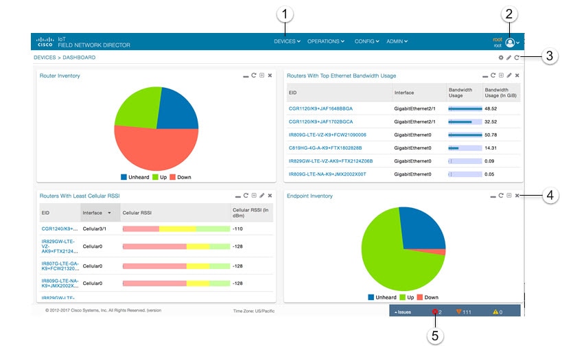
The IoT FND displays the dashboard after you log in (IoT FND Dashboard). See Using the Dashboard.
Define labels, define bulk imports, and More Actions (such as create work orders and block or remove mesh devices) |
|||
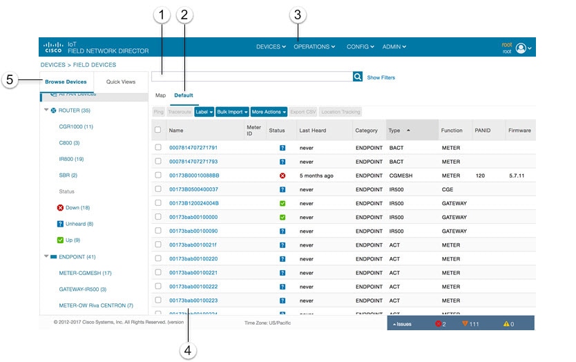
Use the Browse Devices pane (5) to view default and custom groups of devices. At the top of the Browse Devices pane the total number of registered devices displays in parenthesis. The total number of devices in groups displays in parenthesis next to the group name.
You can refine the List display using Filters (1). See Using Filters to Control the Display of Devices. Built-in filters are automatically deployed by clicking a device group in the Browse Devices pane. Use the Quick View tab to access saved custom filters.
Click the device Name or EID (element identifier) link (4) to display a device information page. You can generate work orders directly from the Device Info page, and perform some device-specific tests such as pinging the device to determine if it responds in your network. Click the <<Back link in the Device Info page to return to the page you were on when you clicked the device EID link. Click the refresh button on any page to update the List view.
Each device page has tabs in the main window to view associated information. The active tab is in bold type when you are on that tab (for example, the Default tab in Main Window Elements).
By default, device management pages display in List view, which displays devices in a sortable table. On the Routers and Mesh pages, select the Map tab (5) to display devices on a GIS map (see Viewing Routers in Map View and Viewing Mesh Endpoints in Map View).
Create custom filters by clicking the Show Filters link (the Hide Filters link displays in the same place in Main Window Elements) and using the provided filter parameters (1) to build the appropriate syntax in the Search Devices field (4). Click the Quick Views tab to display saved custom filters (see Creating and Editing Quick View Filters).
Errored Group Name User-entry Field shows an error in the user-entry field. IoT FND displays a red alert icon, highlights the field in red, and disables the OK button. These errors occur, for example, on an invalid character entry (such as, @, #, !, or +) or when an entry is expected and not completed.
Figure 6 Errored Group Name User-entry Field

Icons
IoT FND Icons lists the icons that display in the UI
|
|
|
|---|---|
This router icon is used for CGRs, ISRs, and IRs (routers), and HERs. |
|
This is an endpoint icon. Its color varies based upon status of the device. |
|
The unheard icon indicates that the device has not yet registered with IoT FND. |
|
The outages icon indicates that the device is under power outage. |
|
The restored icon indicates that the device has recovered from an outage. |
|
The default group icon indicates that this is the top-level device group. All devices appear in this group after successful registration. |
|
On the Events page, click this button to initiate an export of event data to a CSV file. |
|
The Group icon indicates that this is a custom device group. |
|
The Custom Label icon indicates a group of devices. Use labels to sort devices into logical groups. Labels are not dependent on device type; devices of any type can belong to any label. A device can also have multiple labels. |
|
On the Dashboard page, click this button to set the refresh data interval and add dashlets. |
|
On the Dashboard page, click this button to initiate an export of dashlet data to a CSV file. |
|
On the Dashboard page, click this button to refresh dashlet data. |
|
On the Dashboard page, click this button to change the data retrieval interval setting and add filters to the dashlets. On line-graph dashlets, this button not only provides access to the data retrieval interval setting and filters, but you can also access graph-specific data settings. This icon is green when a filter is applied. |
|
On the Dashboard page in the dashlet title bar, click this button to show/hide the dashlet. When the dashlet is hidden, only its title bar displays in the Dashboard. |
|
In Map view, this is the RPL tree root device icon. This can be a CGR or mesh device, as set when Configuring RPL Tree Polling. The colors reflect the device status: Up, Down, and Unheard. The RPL tree connection displays as blue or orange lines. |
|
In Map view, this is a device group icon. The colors reflect the device status: Up, Down, and Unheard. |
|
On the Events and Issues pages, and on the Issues Status bar, these icons indicate the event severity level, top-to-bottom, as follows: Each event type has a preset severity level. For example, a Router Down event is a Major severity level event. |
|
On the Firmware Update page, click the Schedule Install and Reload button to configure firmware updates. |
|
On the Firmware Update page, click the Set as Backup button to set the selected image as the firmware image backup. |


Main Menus
This section describes the IoT FND menus available in the title bar at the top of the page.
Devices Menu
The Devices menu provides access to the Dashboard and the device management pages:
■![]() Dashboard—This user-configurable page displays information about the connected grid.
Dashboard—This user-configurable page displays information about the connected grid.
■![]() Field Devices—This page displays a top-level view of registered routers and mesh endpoints in your grid.
Field Devices—This page displays a top-level view of registered routers and mesh endpoints in your grid.
■![]() Head-End Routers—This page displays a top-level view of registered HERs in your grid.
Head-End Routers—This page displays a top-level view of registered HERs in your grid.
■![]() Servers—This page displays a top-level view of IoT FND and database servers in your network.
Servers—This page displays a top-level view of IoT FND and database servers in your network.
■![]() Assets—This page displays non-Cisco equipment that is mapped to Cisco equipment that is managed by IoT FND. Up to five assets can be mapped to a Cisco device and you can upload up to five files (such as.jpeg or.txt) that support those assets.
Assets—This page displays non-Cisco equipment that is mapped to Cisco equipment that is managed by IoT FND. Up to five assets can be mapped to a Cisco device and you can upload up to five files (such as.jpeg or.txt) that support those assets.
Operations Menu
The Operations menu provides access to the following tabs:
■![]() Events—This page displays events that have occurred in your grid.
Events—This page displays events that have occurred in your grid.
■![]() Issues—This page displays unresolved network events for quick review and resolution by the administrator.
Issues—This page displays unresolved network events for quick review and resolution by the administrator.
■![]() Tunnel Status—This page lists provisioned tunnels and displays information about the tunnels and their status.
Tunnel Status—This page lists provisioned tunnels and displays information about the tunnels and their status.
■![]() Work Orders—Use this page to create and monitor work orders.
Work Orders—Use this page to create and monitor work orders.
Config Menu
The Config menu provides access to the following tabs:
■![]() Device Configuration—Use this page to configure device properties.
Device Configuration—Use this page to configure device properties.
■![]() Firmware Update—Use this page to install a new image on one or multiple devices, change the firmware group of a device, view the current firmware image on a device (routers, endpoints) and view subnet details on mesh endpoints.
Firmware Update—Use this page to install a new image on one or multiple devices, change the firmware group of a device, view the current firmware image on a device (routers, endpoints) and view subnet details on mesh endpoints.
■![]() Device File Management—Use this page to view device file status, and upload and delete files from FARs.
Device File Management—Use this page to view device file status, and upload and delete files from FARs.
■![]() Rules—Use this page to create rules to check for event conditions and metric thresholds.
Rules—Use this page to create rules to check for event conditions and metric thresholds.
■![]() Tunnel Provisioning—Use this page to provision tunnels for devices.
Tunnel Provisioning—Use this page to provision tunnels for devices.
Admin Menu
The Admin menu is divided into two areas for managing system settings and user accounts:
–![]() Domains—Use this page to add domains and define local or remote administrators and users.
Domains—Use this page to add domains and define local or remote administrators and users.
–![]() Password Policy—Use this page to set password conditions that user passwords must meet.
Password Policy—Use this page to set password conditions that user passwords must meet.
–![]() Remote Authentication—Use this page to configure remote authentication for IoT-DM users.
Remote Authentication—Use this page to configure remote authentication for IoT-DM users.
–![]() Roles—Use this page to define user roles.
Roles—Use this page to define user roles.
–![]() Users—Use this page to manage user accounts.
Users—Use this page to manage user accounts.
–![]() Active Sessions—Use this page to monitor IoT FND sessions.
Active Sessions—Use this page to monitor IoT FND sessions.
–![]() Audit Trail—Use this page to track user activity.
Audit Trail—Use this page to track user activity.
–![]() Certificates—Use this page to manage certificates for CSMP (CoAP Simple Management Protocol), IoT-DM, and the browser (Web) used by IoT FND.
Certificates—Use this page to manage certificates for CSMP (CoAP Simple Management Protocol), IoT-DM, and the browser (Web) used by IoT FND.
–![]() Data Retention—Use this page to determine the number of days to keep event, issue, and metric data in the NMS database.
Data Retention—Use this page to determine the number of days to keep event, issue, and metric data in the NMS database.
–![]() License Center—Use this page to view and manage license files.
License Center—Use this page to view and manage license files.
–![]() Logging—Use this page to change the log level for the various logging categories and download logs.
Logging—Use this page to change the log level for the various logging categories and download logs.
–![]() Provisioning Settings—Use this page to configure the IoT FND URL, and the Dynamic Host Configuration Protocol v4 (DHCPv4) Proxy Client and DHCPv6 Proxy Client settings to create tunnels between CGRs and ASRs.
Provisioning Settings—Use this page to configure the IoT FND URL, and the Dynamic Host Configuration Protocol v4 (DHCPv4) Proxy Client and DHCPv6 Proxy Client settings to create tunnels between CGRs and ASRs.
–![]() Server Settings—Use this page to view and manage server settings.
Server Settings—Use this page to view and manage server settings.
–![]() Syslog Settings—Use this page to view and manage syslog settings.
Syslog Settings—Use this page to view and manage syslog settings.
 Feedback