Product Overview

Cisco Catalyst IR8340 Rugged Series Router is an industrial grade routing platform with higher port density, higher throughput, native FOG computing, compute capabilities, and enhanced security functionalities.

These topics are discussed:

Chassis Views

The IR8340 router chassis is designed to accommodate Pluggable Interface Module (PIM), Industrial Router Network Interface Module (IRM-NIM), mSATA module, and Timing module.

This section has views of the IR8340 router, showing locations of the interfaces, module slots, status indicators, and chassis identification labels. The following figure shows the Cisco IR8340 Router chassis.

Figure 1. IR8340 Router Chassis

Hardware Features

This section describes the hardware features of the IR8340 router.

Figure 2. IR8340 Router Front Panel

1

Four 10/100/1000Base-T PoE/PoE+/UPoE LAN ports

9

Grounding point

2

Four 100/1000 SFP LAN ports (top)

Four 10/100/1000 Base-T LAN ports (bottom)

10

Power input terminal

3

Four 100/1000 SFP LAN ports

11

USB port

4

Two 100/1000 SFP WAN ports (top)

Two 10/100/1000 Base-T WAN ports (bottom)

12

Console port

5

mSATA module slot

13

Alarm port

6

Timing module slot

14

Two PIM slots

7

SD flash card slot

15

Two IRM-NIM slots

8

System and port LEDs

Alarm Ports

The router has two alarm inputs and one alarm output.

Alarm Input

The alarm input is a dry-contact alarm port. You can connect up to two alarm inputs from devices, such as a door, a temperature gauge, or a fire alarm, to the alarm port. You can use the CLI to set the alarm severity to minor, or major. An alarm generates a system message and turns on an LED. See Cable Side View LEDs for the LED descriptions.

Alarm Output

The alarm output can be configured as a major alarm. Output alarms often control an external alarm, such as a bell or a light. To connect an external alarm device to the relay, you connect two relay contact wires to complete the electrical circuit. For for information on the alarm pinouts. see Alarm Port.

Console Port

You can connect the router to a PC running Microsoft Windows or to a terminal server through the RJ-45 console port. The RJ-45 connection uses an RJ-45-to-DB-9 female cable.

Power-Input Terminal

The power-input terminal provides screw terminals for the AC and DC power connections. The router can operate with one or two power supplies. If one of the power sources fail, the other continues to power the router. See Power Supply Installation for more information.

100/1000 SFP Ports (Uplinks)

The uplink ports support 100M optics and 1G optics. When using a 1000BaseT SFP, the port only operates at 1000 mbps.

100/1000 SFP Ports (Downlinks)

The router Ethernet SFP modules provide connections to other devices. These field-replaceable transceiver modules provide the downlink interfaces. The IR8340 router supports both FE and GE optics in the downlinks. SFP modules have local connectors (LCs) for fiber-optic connections.

For information about SFP modules, see your SFP module documentation. For more information about SFP modules and cables, see Transceiver Modules .

The small form factor pluggable (SFP) ports on the Cisco IR8340 router support the following SFP modules:

Table 1. Supported SFP Modules

Part Number

Type of SFP Module

GLC-SX-MM-RGD

GLC-LX-SM-RGD

GLC-ZX-SM-RGD

GLC-FE-100LX-RGD

GLC-FE-100FX-RGD

GLC-T-RGD

Industrial temperature range (IND): -40 to 85°C (-40 to 185°F)

GLC-BX-U

GLC-BX-D

GLC-FE-100BX-D

GLC-FE-100BX-U

GLC-FE-100FX

GLC-FE-100LX

GLC-FE-100EX

GLC-FE-100ZX

CWDM-SFP-xxxx

DWDM-SFP-xxxx

Commercial SFPs

Commercial temperature range (COM): 0 to 70°C (32 to 158°F)

GLC-SX-MMD

GLC-LH-SMD

GLC-EX-SMD

GLC-ZX-SMD

GLC-TE

Extended temperature range (EXT): -5 to 85°C (23 to 185°F)

10/100/1000 PoE/PoE+/UPoE Ports (Downlinks)

You can set the 10/100/1000 ports on the router to operate in any combination of half duplex, full duplex, or 10/100/1000 Mb/s. You can set the ports for speed and duplex autonegotiation. The default setting is autonegotiate.

When set for autonegotiation, the router determines the speed and duplex settings of the attached device and advertises its own capabilities. If the connected device also supports autonegotiation, the router negotiates the best connection (the fastest line speed that both devices support and full-duplex transmission if the attached device supports it) and configures itself accordingly. In all cases, the attached device must be within 328 feet (100 meters).


Warning


Voltages that present a shock hazard may exist on Power over Ethernet (PoE) circuits if interconnections are made using uninsulated exposed metal contacts, conductors, or terminals. Avoid using such interconnection methods, unless the exposed metal parts are located within a restricted access location and users and service people who are authorized within the restricted access location are made aware of the hazard. A restricted access area can be accessed only through the use of a special tool, lock and key or other means of security. Statement 1072


The 10/100/1000 PoE ports on the router provide PoE support for devices that are compliant with IEEE 802.3af/802.3at. The Cisco prestandard PoE is also supported for Cisco IP Phones and Cisco Aironet Access Points. The PoE ports on the router deliver up to 30 W of PoE+ power. All four ports are PoE ports and can be assigned a port priority.

On IR8340, GigabitEthernet 0/1/0 and GigabitEthernet 0/1/1 support POE/POE+/UPOE, GigabitEthernet 0/1/2 and GigabitEthernet 0/1/3 support POE/POE+ only.

On a per-port basis, you control whether or not a port automatically provides power when an IP phone or an access point is connected.

The 10/100/1000 PoE ports use RJ-45 connectors with Ethernet pinouts. The maximum cable length is 328 feet (100 meters). The 100BASE-TX and 1000BASE-T traffic requires CAT5, CAT5e, or CAT6 shielded twisted-pair (STP) cable. The 10BASE-T traffic can use CAT3 or CAT4 shielded twisted pair (STP) cable.

For information about configuring and monitoring PoE ports, see the router software configuration guide on Cisco.com.


Note


The output of the PoE circuit has been evaluated as a Limited Power Source (LPS) per IEC 60950-1.

mSATA Module

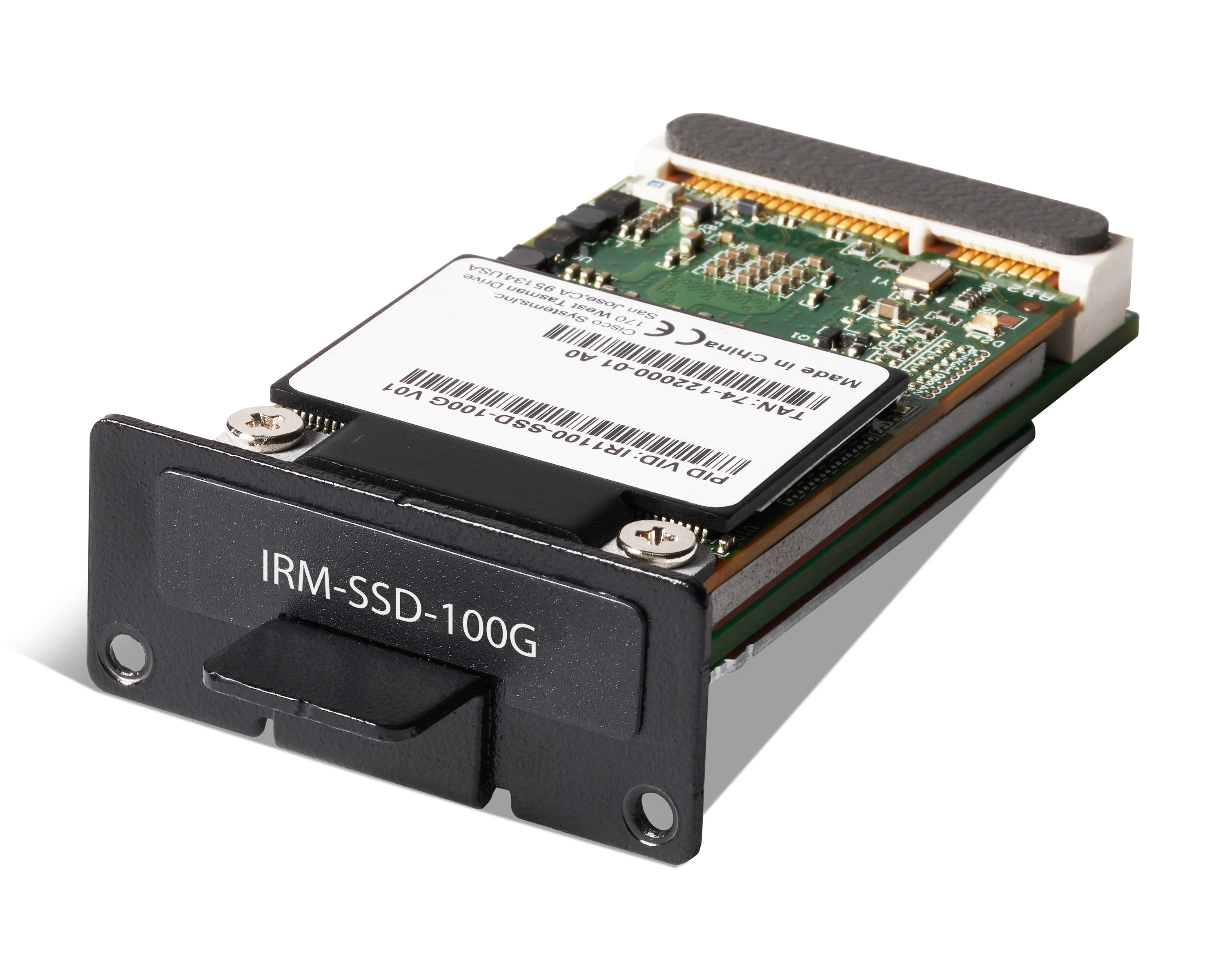
Mini-SATA, or mSATA, is a low-profile interface connector that enables more effective Serial ATA (SATA) integration in small form-factor drives roughly the size of a business card, such as solid state disks (SSDs). The Cisco IR8340 router provides an expand slot to accommodate the mSATA module (PID: IRM-SSD-100G). The following figure shows the mSATA Pluggable Module.

Figure 3. mSATA Module

Highlights of the mSATA Pluggable Module are:

  • Provides an additional 100 GB of additional flash memory storage

  • Field replaceable unit, not hot-swappable

Timing Module

The IR8340 router supports a pluggable timing module (Cisco PID: IRM-TIMING-MOD), which has the following timing ports:

  • ToD + 1 PPS Output—Provide time of day (ToD) messages or one pulse-per-second (1 PPS) messages

  • IRIG-B (analog and digital Input/Output) interfaces

  • GNSS Receiver

Figure 4. IRM-TIMING-MOD Timing Module

Timing card is pluggable but does not support OIR operation. The module has to be plugged in when the IR8340 is fully shut down.

SD Flash Memory Card

The Cisco IR8340 router supports a flash memory card that makes it possible to replace a failed router without reconfiguring the new router. The slot for the flash memory card is on the front of the router. The flash card is hot swappable and can be accessed on the front panel in non hazardous locations only. A cover protects the flash card and holds the card firmly in place. The cover is hinged and closed with a captive screw. This prevents the card from coming loose and protects against shock and vibration.

For more information on inserting and removing the flash memory card, see Replacing the SD Flash Memory Card.

Network Interface Modules

The Network Interface Modules (NIMs) support data applications on the Cisco IR8340 router.

The following NIMs are supported:

  • IRM-NIM-2T1E1—2 ports T1/E1 module, provides T1/E1 connectivity to the router.

  • IRM-NIM-RS232—8 ports async/sync RS232 serial module, provides serial connectivity to the router.

Cisco Pluggable Modules

The Pluggable Module provides the flexibility of adding different interfaces to the IR8340 router, for example, a cellular module.

The IR8340 router supports the following Pluggable Modules:

  • P-LTE-MNA

  • P-LTEA-EA

  • P-LTEA-LA

  • P-LTEAP18-GL

  • P-5GS6-GL

Table 2. Thermal Mitigation Table for P-LTEA7-XX modules - IR8340
MaximumAmbient Temperature (C/F) AirFlow (LFM)

ThroughputPerformance

IR8340

Single P-LTEA7-XX

55℃/131℉

0

Normal

60℃/140℉

0

Throttled

70℃/158℉

40

Throttled

75℃/167℉

200

Throttled

Pluggable LTE Module

Highlights of the LTE Pluggable Module are:

  • All Cellular interfaces are supported through a pluggable module.

  • Micro-Sim, 3FF size. Cisco recommends Industrial Temp micro SIMs that are rated from -40 to +105°C.

The following two figures show an example of a pluggable module. In this case, the LTE Pluggable Module.

Figure 5. PIM Module

1

Cellular-Main SMA

5

SIM 0 LED

2

GPS SMA

6

SIM 1 LED

3

Cellular-Div SMA

7

GPS LED

4

Enable LED

8

RSSI LEDs

Figure 6. LTE Pluggable Module (With Antennas)

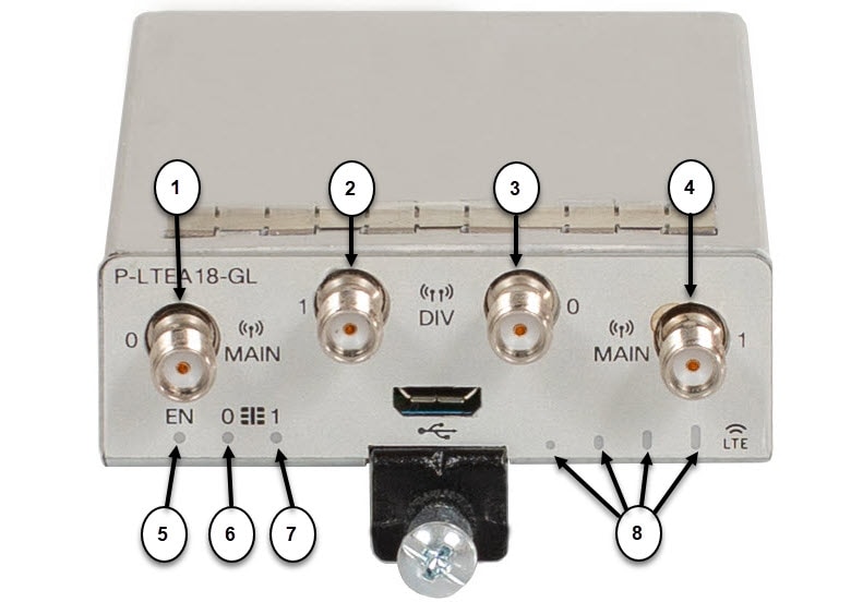
LTE Category 18 Pluggable Module

This module has a new smaller form factor SMA Diversity Antenna for usability and Micro-USB port access.

Figure 7. LTE Pluggable P-LTEAP18-GL

1

Main 0 Antenna

5

Enable LED

2

Diversity 1 Antenna

6

SIM 0 LED

3

Diversity 0 Antenna

7

SIM 1 LED

4

Main 1 Antenna

8

RSSI LEDs

P-LTEAP18-GL Frequency Bands

The following table provides the global frequency bands available.


Note


Antennas must be attached to the RF connectors as listed below for proper bands service.

Item

Description

MAIN 0 and DIV 0

B1, B2(B25), B3, B4(B66), B5(B26,B18,B19), B8, B12(B17), B13, B14, B20, B28, B29, B39, B71, B41

MAIN 1 and DIV 1

B7, B30, B32, B38, B40, B41, B42, B46, B48, B2(B25)

5G Pluggable Interface Module

The 5G Sub-6 GHz Pluggable Interface Module offers 5G capability to the IoT Industrial Router family. The product ID for the pluggable module is P-5GS6-GL. The P-5GS6-GL uses the FN980 Telit modem.


Note


IOS XE release 17.8.1 is the first software release to provide support for the P-5GS6-GL on IR8340 router.


The following features and limitations apply across all IoT routing platforms unless specifically mentioned:

  • IoT routing platforms support a maximum of two pluggable modules, with a combination of 5G and 4G PIMs.

  • The pluggable module can be started or stopped through the CLI under exec mode. Also, it can be configured to power off the module to reduce power consumption as needed.

  • The capability to disable FDD Band 30 for vehicular applications is available.

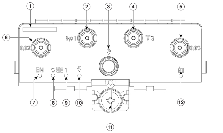
The following figure shows the P-5GS6-GL pluggable module:

Figure 8. 5G Pluggable Interface Module - P-5GS6-GL
1 Printed PID label 7 Enable LED
2 Antenna 1 (SMA) 8 SIM 0 LED
3 GPS (SMA) 9 SIM 1 LED
4 Antenna 3 (SMA) 10 GPS LED
5 Antenna 0 (SMA) 11 M3.5 thumb-screw
6 Antenna 2 (SMA) 12 Service LED

For more information on P-5GS6-GL module, see the 5G Sub-6 GHz Pluggable Interface Module chapter of Cisco Catalyst IR1800 Rugged Series Router Hardware Installation Guide.

Supported Cisco Antennas and Antenna Accessories

The IR8340 must have a Pluggable Module with antenna ports installed in order to connect antennas. The base unit does not have any wireless capabilities on its own.

The Antenna Selection and Installation chapter lists the supported Antennas and Accessories for the Cisco IR8340 router with a wireless Pluggable Module. For detailed information about Cisco Antennas for the Industrial Routers, please refer to Cisco Industrial Routers and Industrial Wireless Access Points Antenna Guide .

LEDs

You can use the system and port LEDs to monitor router activity and performance.

Cable Side View LEDs

Figure 9. LEDs

The following table describes the IR8340 router LED indicators.

Table 3. Cisco IR8340 Router LED Indicators

LED

Port LED Color

Description

SYS

Off

Power is off.

Solid green

Normal operation.

Blinking green

POST in progress.

Solid red

Power is on but malfunctioning.

ACT

Solid or blinking green

Solid or blinking indicates packet activity between the forwarding and routing engine and any I/O port.

Off

No activity.

IRM-NIM 0

IRM-NIM 1

Green

Present and operating.

Red

Any port on the module presents failure.

Off

Not present or not powered.

PIM 0

PIM 1

Green

Present and operating.

Amber

Any port on the module presents failure.

Off

Not present or not powered.

Port Link

Off

No link.

Green

Link up. No activity.

Blinking green

Link up with active traffic.

Alternating green/amber

SFP not supported or link fault.

Amber

Port disabled.

PSU 1

PSU 2

Green

Valid input is present, and the output is within the operating range.

Red

Valid input is present, and the output is outside the operating range or is not present.

Blinking red

Power-supply module (1 or 2) is installed but valid input is not present.

Off

Power-supply module (1 or 2) is not installed.

SD

Fast blinking amber

Unsupported SD flash memory card is detected.

Slow blinking amber

SD flash memory card is not present.

Solid green

SD flash memory card is functioning.

Solid amber

Error accessing SD flash card. No IOS boot image found.

Blinking green

SD flash memory card transfer in progress.

GPS

Solid green

Active with satellite fix.

Blinking green

Attempting to acquire satellite fix.

Blinking amber

Antenna fault.

Off

GPS is not configured.

ALARMS IN 1-2

Green

No alarm.

Solid red

Major alarm present.

Blinking red

Critical alarm present.

ALARMS OUT

Solid green

No alarm.

Solid red

Relay closed. Alarm present.

mSATA

Off

The mSATA module is not detected.

Green

The mSATA module is presend and enabled.

Amber

Initialized with error.

T-code (Timecode)

Off

Timing card not detected.

Solid green

Timecode input signal present.

Alternating green/amber

Signal present with errors.

Blinking amber

Timecode input configured, but no signal present.

REDUN (Redundancy Status)

Solid green

Redundancy protocols are configured and active.

Solid amber

Redundancy fault detected.

SYNC (SyncE Status)

Off

Free run.

Solid green

System is synced to an external source.

Solid amber

One or more configured timing sources has a fault or is not present.

PoE Port LED (Port PoE/PoE+/UPOE)

Off

PoE/PoE+/UPoE is disabled.

Green

Port is delivering power.

Amber

PoE is enabled with failure.

Power Supply Side View

The power-supply side has the LED panel and two power-supply slots for the removable power supplies.

Figure 10. IR8340 Router With Both Power Supply Modules

1

Power supply modules

2

Power supply slots

3

LED panel

4

Captive screws

5

Alignment tabs

Power Supply Features

The router has two slots for power-supply modules and supports the following power supplies:

  • PWR-RGD-LOW-DC: low-voltage DC, 24 to 60VDC input, 150 watt output

  • PWR-RGD-AC-DC: high-voltage AC or DC, 100 to 240VAC/100-250VDC input, 150 watt output

  • PWR-RGD-AC-DC-250: high-voltage AC or DC, 100 to 240VAC/100 to 250VDC input, 250 watt output


Note


For detailed specifications, see the IR8340 data sheet.

The router supports these power-supply module combinations:

  • Single low-voltage DC

  • Single high-voltage DC or AC

  • Two high-voltage DC or AC

  • Two low-voltage DC

  • One high-voltage DC or AC and one low-voltage DC