Route Processor Multi Chassis Card
The Route Processor Multi Chassis (RPMC) card (PID: NCS4KF-RPMC) is a 56-port combination card. The RPMC card integrates a Shelf Controller and the Switch for the NCS 4000 Control Ethernet into one physical card. The RPMC card controls the route processing, the fabric cards, and the management functions for the FCC and its components. The alarm LEDs on the RPMC card indicate active alarm conditions.
The RPMC cards are inserted into two dedicated slots on the front of the FCC. One RPMC card installs into slot RPMC0 SC0/SW0 on the upper card cage, and the other installs into slot RPMC1 SC1/SW1 on the lower card cage. Both the upper and lower cardslots are identical. The secondary card is installed for redundancy, so that the loss or removal of a single card does not bring down the FCC. At least one RPMC card must be operational for the FCC to function.
The cable management brackets are preinstalled on the RPMC card.
 Caution |
All SFP+ and QSFP+ optical ports on the RPMC card are required to be populated with either SFP+/QSFP+ optics or SFP+/QSFP+ dust plugs. This requirement is to adhere to the system EMC and safety compliance guidelines. |
 Note |
Only two RPMC cards, with their switch portions operational (that is, participating in Ethernet control plane traffic), are supported in an entire multichassis system. |
|
Card Type |
Height |
Depth |
Width |
Weight |
|---|---|---|---|---|
|
RPMC |
22.37 in. (56.8 cm) including ejector projection at sides. |
2.75 in. (7.0 cm) 3.45 in. (8.76 cm) without exterior cosmetics. |
11.19 in. (28.4 cm) without ejector projection from faceplate. |
14.96 lb (5.89 kg) |
|
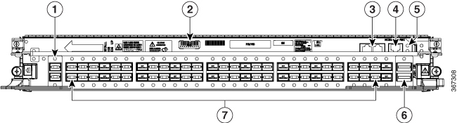
1 |
Two 10GE expansion ports (EXP 0 and EXP 1) |
5 |
USB 2.0 port |
|
2 |
Serial number label |
6 |
Two QSFP+ 40GE optical ports (HS0 and HS1) |
|
3 |
Two EIA232 serial console ports: (CON 0 and CON1) |
7 |
56 SFP+ 10GE optical ports, left to right (0–27 at bottom, 28–55 at top) |
|
4 |
RJ-45 Ethernet management port |
The RPMC card's external ports include:
-
10GE expansion ports: used to expand the internal control Ethernet network to the LCC by connecting through the SW switch ports. The ports are identical in functionality. Each port can handle 10GE operations through the SFP+ modules. The supported SFP+ modules are: ONS-SC+-10G-LR and ONS-SC+-10G-SR.
-
EIA-232 serial console ports.
-
RJ-45 Ethernet management port: RJ-45 copper10/100/1000 Mbps full duplex port.
-
USB2.0 port (type A receptacle): used to attach a storage device to the FCC. This USB port is used only for storage devices.
-
QSFP+ 40GE optical ports: Quad Small-Form-factor Pluggable (QSFP) 40GE ports that are used for communication between two RPMC cards. The supported QSFP+ module is, QSFP-40G-SR4.
-
SFP+ 10GE optical ports: control plane connectivity between the FCC and the LCC.


 Feedback