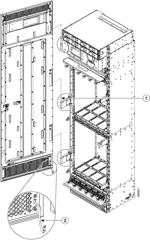
Removing the Power Components
This section describes how to remove power components from the Cisco NCS 4000 FCC.
While it is possible to remove power components from the Cisco NCS 4000 FCC separately, some parts (such as the power tray) require that other parts be removed first.
We recommend that you remove the power components in the order outlined in this section.
Removing DC Input Power Cables
This section describes how to remove DC input power cables from a power tray terminal block.
Prerequisites
Power off the DC power modules in the tray you want to disconnect.
 Note |
Before removal, make sure that the input power cables are not energized. |
Required Tools and Equipment
- ESD-preventive wrist strap
- 6-inch, number-1 Phillips screwdriver
- 3/8-inch ratchet wrench with 7/16-pt. socket
- Voltmeter
To disconnect DC input power cables, follow these steps:
Procedure
|
Step 1 |
Attach the ESD-preventive wrist strap to your wrist and connect its leash to one of the two ESD jacks on the chassis. You can also connect the ESD-preventive wrist strap leash to any bare metal surface on the chassis. |
|
Step 2 |
Using the voltmeter, verify that there is no voltage on the cables that are about to be removed. |
|
Step 3 |
Use the screwdriver to remove the screw that secures the terminal block cover into the mounting standoff. |
|
Step 4 |
Slide the terminal block cover downward. |
|
Step 5 |
Remove the terminal block cover. |
|
Step 6 |
Disconnect the DC power cables from their terminals in the following order and note the color of each cable:
|
|
Step 7 |
Replace the terminal block cover. |
Removing a Power Module Slot Cover
This section describes how to remove a power module slot cover from a power module slot in a DC power tray.
To remove a power module slot cover from the front of a power tray, follow these steps:
Procedure
|
Step 1 |
Gently pinch the tabs on the top of the power module slot cover to partially detach the slot cover from the slot. |
|
Step 2 |
Slide the power module slot cover out by removing the tabs on the bottom of the power module slot cover from the two holes on the bottom of the slot. |
Removing DC Power Module
This section describes how to remove a power module from a power tray.
 Note |
It is not necessary to turn off the switch on the power tray to remove individual power modules. Power modules support OIR, so they can be removed and replaced with the power on and the system operating. |
To remove a power module from the front of a power tray, follow these steps:
Procedure
|
Step 1 |
Release the snap hook on the power module. |
|
Step 2 |
Slide the power module out of its bay in the power tray while supporting it with your other hand. Use the handle available on the front plate of the power module. |
Replacing a Power Module
The following section describes how to replace a power module in a NCS 4000 FCC.
Following are the limitations when a Delta power module (DC power) is replaced with an ACBEL power module (DC power).
-
Release 6.5.25 and 6.5.26 software packages come with ACBEL PEM FPD image with version 4.02. Post upgrade, the state of ACBEL PSU FPD is shown as NOT READY but the power module will function normally.
Follow these steps to replace DC power modules for a chassis:
Procedure
|
Step 1 |
Using two hands to support the power module, slide it into the power tray. |
|
Step 2 |
Secure the power module into the power tray using the snap hook. |
Removing the Chassis Ground Cable
This section describes how to remove the chassis ground cable on the Cisco NCS 4000 FCC.
Prerequisites
Before performing this task, completely power off the entire system. Remove all DC input power connections.
 Caution |
Do not remove the chassis ground cable unless the chassis is powered off and to be replaced. |
Required Tools and Equipment
- 3/8-inch drive socket wrench
- 10-mm 6-pt. socket
Procedure
|
To remove the ground cable from the chassis, remove the two M6 bolts that attach the ground cable to the NEBS grounding point. |


 Feedback