Installing Route Processor Cards, Fabric Cards, and Line Cards

This chapter provides instructions on how to install route processor (RP) cards, fabric cards (FCs), line cards (LCs) and their associated components in the Cisco NCS 4009 chassis.

About Installing Cards and Associated Components

Preventing Electrostatic Discharge

Electrostatic discharge (ESD) damage, which can occur when electronic cards or components are improperly handled, results in complete or intermittent failures. We recommend use of an ESD-preventive wrist strap whenever you handle network equipment or one of its components.

  • Always use an ESD-preventive wrist or ankle strap, and ensure that it makes good skin contact. Connect the equipment end of the connection cord to an ESD jack or a bare metal surface on the chassis (ensure that the chassis is grounded).
  • Handle a card by its ejector levers, when applicable, or its metal carrier only; avoid touching the connector pins. (See the Guidelines for Installing and Removing a Card section of this chapter.)
  • Place the removed card board-side-up on an antistatic surface or in a static-shielding bag. If you plan to return the component to the factory, immediately place it in a static-shielding bag.
  • Avoid contact between a card and clothing. The wrist strap protects the card from only ESD voltage on the body; ESD voltage on clothing can still cause damage.
  • Be careful not to lay any tools on the aluminum honeycomb panel, or insert your fingers into the panel.

Guidelines for Installing and Removing a Card

  • Online (in-service) insertion and removal (OIR) is supported, enabling you to remove and install cards while the chassis is operating. OIR is seamless to users on the network, maintains all routing information, and ensures session preservation. You do not need to notify the software or reset the power. You have the option of using the Cisco IOS XR shutdown command before removing a card.

Note


OIR removes power to a specific slot before the card is replaced. The power for all other cardslots is not impacted.
  • The different cards in the Cisco NCS 4009 chassis are all attached to the chassis itself using a pair of ejector levers and captive screws. The two ejector levers release the card from its backplane connector. The exact locations of the ejector levers and captive screws can vary slightly, depending on the cards. Generally, the ejector levers and captive screws are located at the upper and bottom ends of the faceplate.
  • When you remove a card, press the OIR buttons before using the ejector levers. This action ensures that the connector pins disconnect from the backplane in the sequence as expected by the chassis.
  • The eject symbol on the OIR buttons shows the correct card orientation. The symbol must be oriented upward for cards in the top row, and downward for cards in the bottom row.
  • Every FC, LC, and RP card has a key that is mounted on the board that matches a corresponding slot on the chassis side (top of each cardslot). This key-slot mechanism prevents a card from being inserted into the wrong, nonmatching cardslot. It also prevents a card from being inserted upside down. When a card is inserted into the wrong cardslot or upside down, the key gets blocked against the chassis card guide. This action will not allow the card to slide though the slot. When the key gets blocked, remove the card and find the correct cardslot.

Note


RP card faceplates are labeled with the square symbol. Cardslots on the chassis for RP cards are also labeled with the square symbol. FC faceplates are labeled with the plus symbol. Cardslots on the chassis for FCs are also labeled with the plus symbol.
  • The chassis is shipped with all cardslots containing filler cards to help maintain chassis stiffness and prevent any damage to the chassis during shipment.
  • Any unused cardslots that are uncovered (filler card not installed) act as an escape path for the air. When the air escapes, it results in overheating of the components in the adjacent slots. Therefore, to ensure proper airflow and maintain system EMC and safety compliance, unused LC slots must contain filler cards. All FC and RP cards must remain installed in their cardslots.
  • Fully insert all FC and RP cards into the chassis before tightening their captive screws.
  • For information about the slot numbers, see the “Chassis Slot Numbers” section on page -6 .

Caution


The chassis may indicate a hardware failure if you do not follow proper procedures. Remove or install only one card at a time. Allow at least 30 seconds for the chassis to complete its tasks before removing or installing another card.


Installing and Removing a Filler Card


Caution


To ensure thermal regulation in the chassis, install filler cards in the empty LC slots.


This section contains the following procedures:

Installing a Filler Card

This section describes how to install a filler card in the Cisco NCS 4009 chassis.

Prerequisites

Open the front door, if installed, and ensure that the slot in which you are about to install the filler card is empty.

Required Tools and Equipment

  • Number-2 Phillips screwdriver or number-2 common (flat-head) screwdriver
  • LC filler card (Cisco PID NCS4K-BLANK)
Figure 1. LC Slot Filler Card

Steps

The following steps describe how to install a filler card.

Procedure


Step 1

Orient the filler card, as shown in the preceding figure. The arrow on the faceplate must be facing up to insert the card into the card cage.

Step 2

Use both hands while inserting a filler card. Use one hand on the faceplate and the other hand along the base of the filler card to guide it into the slot.

Step 3

Slide the filler card into the chassis until the captive screw plates are flush with the chassis.

Step 4

Partially tighten the two captive screws on the front panel of the filler card (either by hand or with the number-2 Phillips screwdriver or number-2 common [flat-head] screwdriver) to make sure that they are both engaged.

Step 5

Use the number-2 Phillips screwdriver or number-2 common (flat-head) screwdriver to fully tighten the captive screws to seat the filler card firmly in the slot.


Removing a Filler Card

This section describes how to remove a filler card from the Cisco NCS 4009 chassis.

Prerequisites

Before performing this task, open the front door, if installed.

Required Tools and Equipment

  • Number-2 Phillips screwdriver or number-2 common (flat-head) screwdriver

Steps

The following steps describe how to remove a filler card.

Procedure


Step 1

Identify the filler card to be removed from the card cage. Use the number-2 Phillips screwdriver or number-2 common (flat-head) screwdriver, and turn the two captive screws on the front panel of the card counterclockwise to loosen the card from the slot.

Step 2

Grasp the filler card handle with one hand and gently pull it half-way from the slot.

Step 3

Place one hand under the filler card to guide it.

Step 4

Holding the filler card underneath and by the handle, pull it from the slot, and set it carefully aside.


About RP Cards

The Cisco NCS 4009 chassis supports two Route Processors (RPs). These cards are the intelligence of the system. They function as the shelf controllers for DWDM or OTN applications and by providing route processing and chassis management. The RP cards also monitor system alarms and control the system fans. LEDs on the front panel indicate active alarm conditions.

Two RPs per chassis are required for a redundant system. RP cards are inserted into the two dedicated slots in the chassis.

See the Verifying and Troubleshooting the Installation of an RP Card for details about LEDs, troubleshooting, and the front panel of the RP card.

Physical Characteristics

  • Height—11.05 in. (280.6 mm)
  • Width—1.55 in. (39.4 mm)
  • Depth—14.25 in. (362 mm)
  • Weight—7.32 lb (3.32 kg)

Installing an RP Card

This section contains the following procedures:

Installing an RP Card

Every Cisco NCS 4009 chassis contains two RP cards in dedicated slots that are located on left and right side of the chassis. The RP cards are identical. One RP card installs into slot RP0 on the left side of the chassis. The second RP card installs into slot RP1 on the right side of the chassis. The RP cards are hot-swappable.


Warning


Class 1 Laser Product. Statement 113


Warning


Because invisible radiation may be emitted from the aperture of the port when no fiber cable is connected, avoid exposure to radiation and do not stare into open apertures. Statement 125


Prerequisites

Before performing this task, open the front door, if installed.

Required Tools and Equipment

  • ESD-preventive wrist strap
  • Number-2 Phillips screwdriver or number-2 common (flat-head) screwdriver
  • RP card (Cisco PID NCS4K-RP)
Figure 2. Installing an RP Card

Steps

The following steps describe how to install an RP card.

Procedure


Step 1

Attach the ESD-preventive wrist strap to your wrist. Connect its leash to one of the two ESD jacks that are located on the front or rear side of the chassis. You can also connect the ESD-preventive wrist strap leash to any bare metal surface on the chassis.

Step 2

Remove the card from its antistatic packaging.

Step 3

Place one hand under the card to support and guide it into the correct slot. Slide the card half-way into the slot. Avoid touching the card circuitry or any connectors.

Note

 
Alignment grooves exist on each slot in the card cage. When you install a card in the card cage, make sure that you align both edges of the card carrier in the slot grooves.

Step 4

Orient the RP. The arrows on the OIR buttons must be facing up to insert the card into the card cage.

See RP Card Front Panel for an example of the arrows on the OIR buttons. If the card does not slide easily into the slot, the orientation may be wrong or the slot is not for an RP. Reorient the RP, if necessary.

Step 5

Carefully slide the RP into the slot until the ejector levers meet the edges of the card cage. Stop when the ejector lever hooks catch the card cage. If they do not catch, try reinserting the RP until the ejector lever hooks are fully latched.

Step 6

Press the OIR buttons to release the ejectors.

Step 7

Pivot both card ejector levers so that the openings on the card ejector cams at the top and bottom of the card pass over the tabs on each side of the card cage slot.

Caution


Verify that the openings on the card ejector pass over the tabs; otherwise, one or both ejector levers might bind when you attempt to close the ejector levers, thereby damaging or breaking one or both ejector levers.

Step 8

Continue sliding the card into the card cage slot until the openings on the card ejector cams engage the tabs on each side of the card cage slot.

Note

 
RP cards have guide pins that make initial contact with the backplane connector as you slide the card into its slot. After the guide pins make contact, continue pushing on the card carrier until the card ejector levers begin pivoting forward toward the handle in the card carrier.

Step 9

To seat the card in the backplane connector, grasp both card ejector levers and pivot them inward toward the handle in the card carrier until they are flush against the front edge of the card carrier.

Step 10

Using the number-2 Phillips screwdriver or number-2 common (flat-head) screwdriver, turn the two captive screws on the front panel of the card clockwise to seat the card firmly in the slot. Tighten the captive screws using 10.60 pound/force (lbf) inch (1.20 Nm torque).


Verifying and Troubleshooting the Installation of an RP Card

This section describes how to verify that the RP card has been properly installed and how to troubleshoot the installation in the Cisco NCS 4009 chassis.

Figure 3. RP Card Front Panel

1

Status LED (card status indicator)

8

Active/standby LED

2

Attention LED

9

Acknowledge button

3

Sync LED

10

Lamp test button

4

Disc LED

11

External USB port

5

Critical LED

12

Console ports

6

Major LED

13

RJ-45 10/100/1000 copper full-duplex ports (with status LEDs)

7

Minor LED

14

SFP+ 10GE ports (with status LEDs)


Note


Only the active RP console port sends and receives messages.

Troubleshooting the RP Card

Use the Status LED, located on the faceplate of the RP card, to verify the correct installation of the card:

  • When the card is properly installed and no faults are detected, the card status LED turns green.
  • When the card status LED is solid yellow, either software initialization is in progress during bootup or a fault exists on the board.
  • When the card status LED is blinking yellow, the card is not fully seated.
  • When the card status LED is off, verify that the card is installed correctly. There could be no power applied to the card, a power fault, or a hardware fault.
  • Verify that there is power to the card by looking at the indicators on the power tray.

Note


To confirm the location of the card that needs attention, the Attention LED can be lit by using the hw-module attention-led location CLI command.

If the installed or replaced card fails to operate or to power on after installation:

  • Ensure that the card is seated firmly in the Cisco NCS 4009 chassis slot. One easy way to verify that physical installation is correct to check the front faceplate of the card. The front faceplate should be even with the fronts of the other installed cards.
  • Ensure that the ejector levers are latched and that the captive screws are fastened properly. If you are uncertain, unlatch the levers, loosen the screws, and attempt to reseat the card.
  • Examine the power system to see whether the chassis is receiving power.

In addition to the Status and Attention LEDs, Table 1 describes the other LEDs on the RP card.

Table 1. Other LEDs

LED Name

Description

LED Colors

Sync

Indicates that the RP card is receiving external sync.

Green = in sync

Yellow = out of sync

Disc

Indicates that the Solid State Disk (SSD) on the RP card is accessed.

Green = access occurring

Critical

Indicates a critical system alarm.

Yellow = an active critical system alarm

Major

Indicates a major system alarm.

Yellow = an active major system alarm

Minor

Indicates a minor system alarm.

Yellow = an active minor system alarm

Active/standby

Indicates that the RP card is in active or standby mode.

Green = active

Yellow = standby

RJ45

Indicates the status of the RJ-45 Ethernet link.

Green = on

Yellow = active

SFP+

Indicates the status of the SFP+ 10GE ports.

Green = active

About Fabric Cards

The Cisco NCS 4009 chassis supports 4 fabric cards (FCs). The fabric cards are agnostic cross-connects based on a flexible cell switching architecture that is used in a CLOS configuration. FCs are called agnostic because they switch a cell with no knowledge of whether they belong to OTN or Ethernet. Each fabric card has a crossbar fabric device.

FCs provide the switch fabric for the routing system and perform the cross-connect function, connecting every LC to each other. The switch fabric receives ingress user data from one LC slot and performs the switching necessary to route the data to the appropriate egress LC slot.

The Cisco NCS 4009 chassis supports, the 200G and 400G fabric cards. The 400G fabric card enables 400G traffic using the 400G line card. The datapath link speed of 400G FC-LC is twice that of the 200G FC-LC. The 200G and the 400G fabric cards support single chassis only.

FC Name

Compatible with 200G LC

Compatible with 400G LC

NCS4009-FC-S (200G)

Yes

No

NCS4009-FC2-S (400G)

NCS4009-FC2F-S (400G)

Yes

Yes

An Auxiliary Fan Tray (Cisco PID NCS4009-FAN-FC) is attached to the NCS4009-FC2F-S fabric card. The Auxiliary Fan Tray (AFT) and the fan tray present in the front of the chassis (behind the craft panel), provide cooling for the chassis components. For details, see theAuxiliary Fan Tray Auxiliary Fan Tray section of this chapter.

Caution


The four NCS4009-FC2F-S fabric cards and the four AFTs must be present in the chassis always except during the replacement of the FC or AFT.


See the Verifying the Installation of a Fabric Card for details about LEDs, troubleshooting, and to see the front panel of the FC card.

Physical Characteristics

  • Height—4.05 in. (103.12 mm)

  • Depth (NCS4009-FC2-S)—12.97 in. (329.4 mm)

    Depth (NCS4009-FC2F-S)—15.95 inches (405 mm)

  • Width—4.21 in. (107.18 mm)

  • Weight (NCS4009-FC2-S)—4.4 lb (2 kg)

    Weight (NCS4009-FC2F-S)—5.99 lb (2.718 kg); weight of the FC is 4.96 lb (2.25 kg), weight of the AFT is 1.03 lb (0.468 kg).

Auxiliary Fan Tray

The AFT provides cooling for the chassis by drawing outside air into the chassis.

The AFT is attached to the NCS4009-FC2F-S fabric card in the front. The AFT remains attached to the fabric card always. The only time when the AFT can be detached from the fabric card is when either the fabric card or the AFT has to be replaced. Power is supplied to the AFT through the NCS4009-FC2F-S fabric card.

Note


In case of Envmon process restart, the AFTs run at maximum speed and return to the speed they were earlier running at, after about one minute.


Figure 4. The NCS4009-FC2F-S Fabric Card with the AFT (NCS4009-FAN-FC)
Table 2. Auxiliary Fan Tray

1

Sliding handle

2

Captive screws

NCS4009-FC2-S-KIT comprises the NCS4009-FC2F-S (Fabric Card) and the NCS4009-FAN-FC (Auxiliary Fan Tray).

Installing a Fabric Card

This section contains the following procedures:

Installing a Fabric Card

Prerequisites

Before performing this task, open the front door, if installed.

Required Tools and Equipment

  • ESD-preventive wrist strap
  • Number-2 Phillips screwdriver or number-2 common (flat-head) screwdriver
  • Fabric Card (Cisco PID NCS4009-FC-S or Cisco PID NCS4009-FC2-S or Cisco PID NCS4009-FC2F-S)
Figure 5. Installing a Fabric Card - NCS4009-FC2-S
Figure 6. Installing a Fabric Card - NCS4009-FC2F-S
Figure 7. Installing the AFT

Steps

The following steps describe how to install a fabric card.

See here for a graphical representation of the installation of the NCS4009-FC2F-S fabric card and the AFT.

Procedure


Step 1

Attach the ESD-preventive wrist strap to your wrist and connect its leash to the ESD jack located on the front side of the chassis. You can also connect the ESD-preventive wrist strap leash to any bare metal surface on the chassis.

Step 2

Remove the FC from its antistatic packaging.

Step 3

Place one hand under the card to support and position the card for insertion into the card cage slot. Avoid touching the card circuitry or any connectors.

Note

 
Alignment grooves exist on each slot in the card cage. When you install a card in the card cage, make sure that you align both edges of the card carrier in the slot grooves.

Step 4

Orient the FC correctly, as shown in figure 5.

Step 5

Release the ejector lever by pressing the OIR button.

Step 6

Slide the FC completely into the slot until it engages with the backplane connector and the ejector lever meets the edges of the card cage.

Step 7

Pivot the ejector lever toward the faceplate of the card.

Step 8

Use the number-2 Phillips screwdriver or number-2 common (flat-head) screwdriver to tighten the captive screw using 10.60 pound/force (lbf) inch (1.20-Nm torque).

Make sure that the ejector lever is in the vertical position and the fabric card is firmly inserted before tightening the captive screw.

There are two ways to check if the card is operational.
  • The Status LED on the faceplate turns green.

  • Run the show platform command and check if the fabric card is displayed as OPERATIONAL.

Step 9

To install the AFT, slide the AFT into the frame of the fabric card. The connector on the fabric card holds the AFT firmly to the card.

Step 10

Push the sliding handle to its original position.

Step 11

Use the number-2 Phillips screwdriver or number-2 common (flat-head) screwdriver to tighten the two captive screws on the AFT using 6.2 pound/ force (lbf) inch (0.7-Nm torque).

For NCS4009-FC2F-S, check for the LED status on the AFT, and run the show platform command (as discussed in step 8) after installing the AFT.


Verifying the Installation of a Fabric Card

The following figure shows the front panel of the fabric card.

Figure 8. FC Front Panel - NCS4009-FC2-S
Figure 9. FC Front Panel - NCS4009-FC2F-S
Table 3.

1

Fan Status LED

2

Status LED

3

Attention LED


Note


The LED indications for the NCS4009-FC2F-S fabric card and the AFT are available on the AFT.


Use the Status LED, located on the faceplate of the fabric card, to verify the correct installation of the card and the AFT:

  • When the card is properly installed and no faults are detected, the card status LED turns green.
  • When the card status LED is solid yellow, either software initialization is in progress during bootup or a fault exists on the board.
  • When the card status LED is blinking yellow, the card is not fully seated.
  • When the card status LED is off, verify that the card is installed correctly. There could be no power applied to the card, a power fault, or a hardware fault.
  • Verify that there is power to the card by looking at the indicators on the power tray.
  • The Fan Status LED is green, when the AFT unit is seated correctly and when there are no alarms.
  • The Fan Status LED is red, when there is an alarm or when the module voltage is out of range.

Note


To verify which card needs attention, the Attention LED can be lit using the hw-module attention-led location CLI command.

If the installed or replaced FC fails to operate or power on after installation:

  • Ensure that the card is seated firmly in the Cisco NCS 4009 chassis slot. One easy way to verify physical installation is to see whether the front faceplate of the FC is even with the fronts of the other cards installed in the card cage.
  • Ensure that the ejector lever is latched and that the captive screws are fastened properly. If you are uncertain, unlatch the levers, loosen the screws, and attempt to reseat the FC.
  • Examine the power system to see whether the chassis is receiving power.

Upgrading a Fabric Card

This task enables you to upgrade from the NCS4009-FC2-S fabric card to the NCS4009-FC2F-S fabric card. After the fabric card is upgraded, upgrade the air filter.

The air filter design for NCS4009-FC2-S and NCS4009-FC2F-S fabric cards is different.

The NCS4009-FC2-S fabric card supports Cisco PID NCS4009-FTF.

The NCS4009-FC2F-S fabric card supports Cisco PID NCS4009-FTF-2.

Prerequisites

Before performing this task, open the front door.

Required Tools and Equipment

  • ESD-preventive wrist strap

  • Number-2 Phillips screwdriver

  • FC: NCS4009-FC2F-S

  • AFT: NCS4009-FAN-FC

  • Air filter: NCS4009-FTF-2

Procedure


Step 1

Attach the ESD-preventive wrist strap to your wrist and connect its leash to the ESD jack located at the front side of the chassis. You can also connect the ESD-preventive wrist strap leash to any bare metal surface on the chassis.

Step 2

Remove the air filter. SeeRemoving the Air Filter section in the Removing and Replacing Chassis Components chapter.

Step 3

Identify the NCS4009-FC2-S fabric card to be removed from the card cage and follow the procedure as discussed in the Removing a Fabric Card section in the Removing and Replacing Chassis Components chapter.

Step 4

Install the NCS4009-FC2F-S fabric card and the AFT. Check the status of the newly installed fabric card before proceeding to upgrade the next fabric card. SeeInstalling a Fabric Card section in this chapter.

Attention


Remove and replace the fabric cards, one by one. Wait for the newly installed fabric card to completely come up before removing and inserting the next fabric card. Run the show platform command and check if the fabric card is displayed as OPERATIONAL.

Step 5

Replace the air filter. See Replacing the Air Filter section in the Removing and Replacing Chassis Components chapter.

The supported air filter for the NCS4009-FC2F-S fabric card is Cisco PID NCS4009-FTF-2.

About Line Cards

The Cisco NCS 4009 chassis supports both Optical Transport Network (OTN) line cards (LCs) and Dense Wavelength-Division Multiplexing (DWDM) line cards. You can have a mix of both OTN and DWDM line cards in the same chassis.

This section describes the following line cards:

For a list of the pluggable optics that are supported, see the Pluggable Optics Support.

NCS4K-4H-OPW-QC2 Line Card

The NCS4K-4H-OPW-QC2 line card supports OTN, packet, and WDM switching for 400G traffic and contains:

  • Two CFP2 ports. Each port can support 100 Gbps (DWDM QPSK) or 200 Gbps (DWDM 16 QAM) WDM signals

  • Four QSFP28/QSFP+ ports


    Note


    The QSFP28 ports also support QSFP+ optics and can be used as 1x40G ports or 4x10G ports.


  • Six QSFP+ ports


    Note


    The QSFP+ ports can be split and used as 1x40G ports or 4x10G ports.


The NCS4K-4H-OPW-QC2 line card supports the following port configurations:

  • 2-ports of 200 Gbps with CFP2 optics

  • 4-ports of 100 Gbps with QSFP28 optics, 10-ports of 40 Gbps with QSFP+ optics, or 10 Gbps x 40 ports (4x10G breakout) with QSFP+ optics


Note


When the NCS4K-4H-OPW-QC2 line card, installed in an NCS 4009 chassis, uses the CFP2 ports, the temperature limit is 50o C, and the altitude limit is 1800 meters. Violating these limits, may result in traffic loss. When the NCS4K-4H-OPW-QC2 line card, installed in an NCS 4009 chassis, does not use the CFP2 ports, the temperature limit is 55o C, and the altitude limit is 1800 meters.


Note


When the NCS4K-4H-OPW-QC2 line card, installed in a NCS 4009 chassis, uses QSFP-100G-ER4 optics, the temperature limit is 50° C and the altitude limit is 1800 meters. In the event of a fan tray Online Insertion and Removal (OIR), the maximum time limit is four minutes at 30°C and 1800 meters altitude. Violating these limits, may result in traffic loss. The optics can be inserted in ports 0, 1, 5, and 6. Empty optical ports must covered with dust caps.


The card needs NCS4009-FC2-S fabric card to function in the NCS 4009 chassis.

The card supports OTN and packet aggregation where both TDM switching and packet forwarding capabilities are combined in a single card. Hence, it can terminate both OTN control plane traffic and packet control plane traffic.

The card supports the following data rates:

Protocol

Data Rate

Optic Type

100GE

103.125 Gbps

QSFP28

OTU4

112 Gbps

QSFP28

40GE

41.25 Gbps

QSFP+

OTU3

43 Gbps

QSFP+

OTU3-e1

44.57 Gbps

QSFP+

OTU-3e2

44.58 Gbps

QSFP+

10GE

10.3125 Gbps

QSFP+ BreakOut

OC192

9.953 Gbps

QSFP+ BreakOut

OTU2

10.7 Gbps

QSFP+ BreakOut

OTU2e

11.09 Gbps

QSFP+ BreakOut

OTU2f

11.32 Gbps

QSFP+ BreakOut

2x100G QPSK DWDM

200 Gbps

CFP2 ACO

2x200G 16QAM DWDM

400 Gbps

CFP2 ACO

ODU2e

10.3995253164557

QSFP+ BreakOut

ODU2

10.0372739240506

QSFP+ BreakOut

ODU3

40.3192189830509

QSFP+

ODU3e1

41.774364407

QSFP+

ODU3e2

41.7859685595012

QSFP+

ODU4

104.794445814978

QSFP28

Channelization Support

The NCS4K-4H-OPW-QC2 line card supports up to two levels of channelization. The following tables display the channelization modes supported.

Table 4. Single Channelization Support

Parent Payload

Child Payload 1

Child Payload 2

ODU4

ODU3

-

ODU3e1

-

ODU3e2

-

ODU2

-

ODU2e

-

ODU1

-

ODU1e

-

ODU0

-

ODUflex

-

100GE

GMP

-

GFP-F

-

OTU3

ODU3

-

ODU2

-

ODU2e

-

ODU1

-

ODU0

-

40 GE

GFP-F

-

GMP

-

ODUflex

-

OTU3e1

ODU2e

-

OTU3e2

ODU2e

-

ODU1

-

ODU0

-

ODUflex

-

OTU2

ODU1

-

ODU0

-

ODUflex

-

10GE

GFP-F

-

GFP-F-EXT

-

OC192

AMP

-

BMP

-

Table 5. Dual Channelization Support

Parent Payload

Child Payload 1

Child Payload 2

ODU4

ODU3

ODUflex

ODU0

ODU1

ODU1e

ODU2

ODU2e

ODU3e1

ODU2e

ODU3e2

ODUflex

ODU0

ODU1

ODU2e

ODU2

ODUflex

ODU0

ODU1

ODU1

ODU0

OTU3

ODU2

ODUflex

ODU0

ODU1

ODU1

ODU0

OTU3e2

ODU1

ODU0

ODU2e

ODU1

ODU2e

ODU0

OTU2

ODU1

ODU0

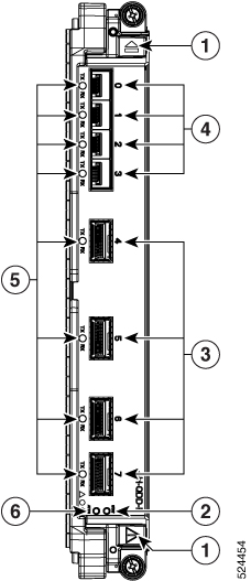
This figure shows the details of the front panel of the NCS4K-4H-OPW-QC2 line card.

Figure 10. Front Panel of the NCS4K-4H-OPW-QC2 Line Card


1

Red ejector

2

Status LED

3

Attention LED

4

CFP2 (DWDM) port

5

QSFP+ port

6

QSFP+ or QSFP 28 port

7

Blue ejector

Table 6. NCS4K-4H-OPW-QC2 Line Card Descriptions

LED

State

Description

Status

Green

The LC is properly seated and operating correctly.

Yellow

The LC has one or more errors detected.

Off

No power is applied to the LC.

Attention 1

Blue

The card needs attention.

Off

The card does not need attention.

Port

Green

The link is up (including internal loopback).

Yellow

The link is down or a hardware failure has occurred.

Off

The slice is unprovisioned by software, the optics module is missing, or the slice has been powered down.

1 The Attention LED can be lit only by using the hw-module attention-led location CLI command, which is useful for identifying and verifying which card needs attention.

Physical Characteristics

  • Height—11.05 in. (280.6 mm)

  • Width—1.55 in. (39.4 mm)

  • Depth—14.25 in. (362 mm)

  • Weight—8.48 lb (3.85 kg)

24-Port Low-Rate OTN Line Card

The 24-port low-rate OTN LC (NCS4K-24LR-O-S) supports up to:

  • 24 1GE interfaces through SFP pluggable optics
  • 16 OC-48/STM-16/OTU1 interfaces through SFP pluggable optics
  • Four 10GE/OC-192/OTU2 interfaces through SFP+ pluggable optics

OTU1 and OTU2 ports support generic forward error correction (GFEC). The card supports ODU2, ODU1, ODU0, and ODUFlex switching functions by interconnecting with the centralized agnostic switch fabric.

Figure 11. 24-Port Low-Rate OTN LC Front Panel and LEDs

1

Status LED

3

Port LEDs (one LED on each port) 2

2

Attention LED

2 Port LEDs are triangular in shape and point toward the port that they support.
Table 7. 24-Port Low-Rate OTN LC Descriptions

LED

State

Description

Status

Green

The LC is properly seated and operating correctly.

Yellow

The LC has one or more errors detected.

Off

No power is applied to the LC.

Attention 3

Blue

The card needs attention.

Off

The card does not need attention.

Port

Green

The link is up (including internal loopback).

Yellow

The link is down or a hardware failure has occurred.

Off

The slice is unprovisioned by software, the optics module is missing, or the slice has been powered down.

3 The Attention LED can be lit only by using the hw-module attention-led location CLI command, which is useful for identifying and verifying which card needs attention.

Physical Characteristics

  • Height—11.05 in. (280.6 mm)
  • Width—1.55 in. (39.4 mm)
  • Depth—14.25 in. (362 mm)
  • Weight—5.5 lb (2.5 kg)

20-Port 10GE OTN Line Card

The 20-port 10GE OTN LC (NCS4K-20T-O-S) line card supports any combination of the following interfaces, up to:

  • 20 10GE interfaces through SFP+ pluggable optics

  • 20 OC-192/STM-64 interfaces through SFP+ pluggable optics

  • 20 OTU2 interfaces through SFP+ pluggable optics

OTU1 and OTU2 ports support generic forward error correction (GFEC). The card supports up to 2-level ODU4, ODU3, ODU2, ODU1, ODU0, and ODUFlex switching functions by interconnecting with the centralized agnostic switch fabric.

The line card also supports direct interconnection to other slots within the Cisco NCS 4009 chassis to interconnect switched OTN traffic directly to the NCS 4000 2 x 100G CP-DQPSK - Full C band Tunable DWDM line card.

Figure 12. 20-Port 10GE OTN LC Front Panel and LEDs

1

Status LED

3

Port LEDs (one LED on each port) 4

2

Attention LED

4 Port LEDs are triangular in shape and point toward the port that they support.
Table 8. 20-Port 10GE OTN LC Descriptions

LED

State

Description

Status

Green

The LC is properly seated and operating correctly.

Yellow

The LC has one or more errors detected.

Off

No power is applied to the LC.

Attention 5

Blue

The card needs attention.

Off

The card does not need attention.

Port

Green

The link is up (including internal loopback).

Yellow

The link is down or a hardware failure has occurred.

Off

The slice is unprovisioned by software, the optics module is missing, or the slice has been powered down.

5 The Attention LED can be lit only by using the hw-module attention-led location CLI command, which is useful for identifying and verifying which card needs attention.

Physical Characteristics

  • Height—11.05 in. (280.6 mm)
  • Width—1.55 in. (39.4 mm)
  • Depth—14.25 in. (362 mm)
  • Weight—5.5 lb (2.5 kg)

2-Port 100GE OTN Line Card

The 2-port 100GE OTN LC (NCS4K-2H-O-K) supports any combination of 100GE and OTU4 interfaces using Cisco CPAK pluggable optics. Two CPAK receptacles are hosted on the faceplate.


Note


Insert CPAK modules in the 2-port 100GE OTN LC handle side down.

The card supports up to two-level ODU4, ODU3, ODU2, ODU1, ODU0, and ODUFlex nested switching functions by interconnecting with the centralized agnostic switch fabric. 100-Gigabit Ethernet signals are mapped using generic mapping procedure (GMP) over ODU4 according to ITU-T G.709 v3 (Section 17.7.5).

Figure 13. 2-Port 100GE OTN LC Front Panel and LEDs

1

Status LED

3

Port LEDs (one LED on each port)

2

Attention LED

Table 9. 2-Port 100GE OTN LC Descriptions

LED

State

Description

Status

Green

The LC is properly seated and operating correctly.

Yellow

The LC has one or more errors detected.

Off

No power is applied to the LC.

Attention 6

Blue

The card needs attention.

Off

The card does not need attention.

Port

Green

The link is up (including internal loopback).

Yellow

The link is down or a hardware failure has occurred.

Off

The slice is unprovisioned by software, the optics module is missing, or the slice has been powered down.

6 The Attention LED can be lit only by using the hw-module attention-led location CLI command, which is useful for identifying and verifying which card needs attention.

Physical Characteristics

  • Height—11.05 in. (280.6 mm)
  • Width—1.55 in. (39.4 mm)
  • Depth—14.25 in. (362 mm)
  • Weight—5.95 lb (2.7 kg)

2-Port 100GE DWDM Line Card

The 2-port 100GE DWDM LC (NCS4K-2H-W) can transport two 100GE or OTU4 signals over a 50 GHz spaced, 50 GHz stabilized, ITU-compliant wavelength with more than 4500 km of unregenerated reach. The card also features two CPAK pluggable optics that can map each client signal to a single DWDM line interface.


Note


Insert CPAK modules in the 2-port 100GE DWDM LC handle side up.
Figure 14. 2-Port 100GE DWDM LC Front Panel and LEDs

1

Status LED

3

Port LEDs, CPAK, and WDM (one LED on each port)

2

Attention LED

Table 10. 2-Port 100GE DWDM LC Descriptions

LED

State

Description

Status

Green

The LC is properly seated and operating correctly.

Yellow

The LC has one or more errors detected.

Off

No power is applied to the LC.

Attention 7

Blue

The card needs attention.

Off

The card does not need attention.

Port

Green

The link is up (including internal loopback).

Yellow

The link is down or a hardware failure has occurred.

Off

The slice is unprovisioned by software, the optics module is missing, or the slice has been powered down.

7 The Attention LED can be lit only by using the hw-module attention-led location CLI command, which is useful for identifying and verifying which card needs attention.

Physical Characteristics

  • Height—11.05 in. (280.6 mm)
  • Width—1.55 in. (39.4 mm)
  • Depth—14.25 in. (362 mm)
  • Weight—7.8 lb (3.53 kg)

Pluggable Optics Support

The following table describes the pluggable optics that are supported on the line cards.

Table 11. Supported Pluggable Optics

Pluggable

Rate and Reach

Product ID

24-Port Low-Rate OTN LC

20-Port 10GE OTN LC

2-Port 100GE OTN LC

NCS4K-4H-OPW-QC2 LC

SFP+

10GE SR/SW

ONS-SC+-10G-SR=

X

X

-

-

10GE LR/LW OC-192 SR STM-64 I-64.1 OTU2 P1I1 2D1

ONS-SC+-10G-LR=

X

X

-

-

10GE ER/EW OC-192 IR-2 STM-64 S-64.2 OTU2 P1S1-2D2

ONS-SC+-10G-ER=

X

X

-

-

10GE ZR OC192 LR-2 STM-64 L-64.2 OTU2 P1L1-2D2

ONS-SC+-10G-ZR=

X

X

-

-

C-band tunable

ONS-SC+-10G-C=

X

X

-

-

CPAK

100GE SR10

CPAK-100G-SR10

-

-

X

-

100GE LR4 OTU4 4I1-9D1F

CPAK-100G-LR4

-

-

X

-

QSFP28

100-Gbps Multirate QSFP28, LR

ONS-QSFP28-LR4

-

-

-

X

QSFP

100Gbps QSFP

QSFP-100G-FR-S

-

-

-

X

100Gbps QSFP

QSFP-100G-LR4-S

-

-

-

-

QSFP+

4X10G Multirate LR4 QSFP+

QSFP-4X10-MLR

-

-

-

X

QSFP 40G Ethernet - LR4 Lite, LC, 2KM, Enterprise-Class

QSFP-40G-LR4

-

-

-

X

QSFP 40GBASE-ER4 Transceiver Module, LC, 40KM

QSFP-40G-ER4

-

-

-

X

CFP2

100G QPSK / 200G 16-QAM - WDM CFP2 Pluggable

CFP2

-

-

-

X

Installing a Line Card

This section contains the following procedures:

Installing a Line Card

Prerequisites

Before performing this task, open the front door, if installed.


Caution


Remove or install only one LC at a time. Allow at least 30 seconds for the chassis to complete its tasks before removing or installing another LC. The chassis may indicate a hardware failure if you do not follow proper procedures.


Required Tools and Equipment

  • ESD-preventive wrist strap
  • Number-2 Phillips screwdriver or number-2 common (flat-head) screwdriver
  • LC
Figure 15. Installing a Line Card

Steps

The following steps describe how to install a line card.

Procedure


Step 1

Attach the ESD-preventive wrist strap to your wrist and connect its leash to the ESD jack located on the front or rear of the chassis. You can also connect the ESD-preventive wrist strap leash to any bare metal surface on the chassis.

Step 2

Remove the filler card and set it aside.

Note

 
Remove only one filler card and install only one LC at a time. Be sure to verify that each LC is fully installed and secured before installing another card.

Step 3

Remove the LC from the antistatic bag.

Caution


To prevent ESD damage, handle an LC by its ejector levers or the LC carrier edges only. Do not touch any of the electrical components, pins, or circuitry.

Step 4

Orient the LC. The arrows on the OIR buttons must be facing up.

See RP Card Front Panel for an example of the arrows on the OIR buttons. If the card does not slide easily into the slot, the orientation may be wrong. Check if the rejection flange is stopping the card from going into the slot. Reorient the LC, if necessary.

Step 5

Use both hands while inserting an LC. Use one hand on the faceplate and the other hand along the base of the LC to guide it into a slot.

Step 6

Press the OIR buttons to release the ejectors.

Caution


When adjusting the ejector levers, avoid hitting the top and bottom fiber management features and doors.

Step 7

Make sure that the ejector levers are oriented properly to engage with the pin as the LC slides into the slot. Carefully slide the LC into the slot until the ejector levers engage the catches, and then stop.

Step 8

Simultaneously pivot the ejector levers toward the faceplate of the LC. Do not force the LC; the ejector levers properly seat the LC against the backplane.

Note

 
If the captive screws are difficult to tighten, ensure that each ejector lever is properly secured to each catch and that the LC is properly seated in the slot.

Step 9

Use a number-2 Phillips screwdriver or number-2 common (flat-head) screwdriver to tighten the captive screws next to each LC ejector lever to ensure proper EMI shielding. The tightening also prevents the LC from becoming partially dislodged from the backplane. Tighten the captive screws using 10.60 pound/force (lbf) inch (1.20 Nm torque).

Step 10

Before attaching the vertical cable management bracket, ensure that the LC has been installed properly. See the Verifying the Installation of a Line Card.

Step 11

Attach the vertical cable management bracket to the faceplate of the LC using the two screws that came with it. The dark gray arm should be facing up, and the light gray arm should be facing down.

Figure 16. Attaching the Vertical Cable Management Bracket

Verifying the Installation of a Line Card

Use the Status LED, located on the faceplate of the LC, to verify the correct installation of the LC:

  • When the card is properly installed and no faults are detected, the status LED turns green.
  • When the status LED is solid yellow, either software initialization is in progress during bootup or a fault exists on the card.
  • When the status LED is blinking yellow, the card is not fully seated.
  • When the status LED is off, verify that the card is installed correctly. There could be no power applied to the card, a power fault, or a hardware fault.
  • Verify that there is power to the card by looking at the indicators on the power tray.

If the installed or replaced LC fails to operate or to power on after installation:

  • Ensure that the card is seated firmly into the Cisco NCS 4009 chassis slot. One easy way to verify the physical installation is to see whether the front faceplate of the card is even with the fronts of the other installed cards.
  • Ensure that the ejector levers are latched and that the captive screws are fastened properly. If you are uncertain, unlatch the levers, loosen the screws, and attempt to reseat the card.
  • Examine the power system to see whether the chassis is receiving power.

Connecting Line Card Network Interface Cables

This section describes how to route the network interface cables through the chassis cable management tray and how to attach the network interface cables to the line card ports.

This procedure uses an 20x10GE OTN line card as an example to describe how to attach a network interface cable to a line card port and route the cable through the cable management tray. Depending on which line cards are installed in your system, your cable connection procedure may differ slightly from this example.


Note


For the cable connection information for your specific line card, refer to the installation and configuration note for that line card. You can access the most current Cisco line card documentation online at: http://www.cisco.com.

Steps

Follow these steps as an example to route the network interface cables through the cable management tray and connect them to the line card:

Procedure


Step 1

Route an interface cable across the horizontal cable management tray and down through the cable tray opening to connect it to the line card.

Figure 17. Routing Interface Cables Through the Cable Management Tray

Step 2

Attach a line card cable management bracket to the line card front panel. This bracket is shipped with the line card.

Figure 18. Attaching a Line Card Cable Management Bracket

Step 3

Insert the cable connector into its assigned port.

Note

 
You can use the clamp tool (provided in the chassis installation kit) to help insert (or remove) cable connectors (and pluggables).

Step 4

Install pluggables and fiber connectors.

Step 5

Repeat Step 1 through Step 4 for each additional cable connection to that line card.

Step 6

Affix fibers to the vertical brackets. The final connections should appear similar to the following figure.

Figure 19. Interface Cable Routing Using the Line Card Cable Management Bracket

Caution


Make sure that the interface cables do not have any kinks or sharp bends, which can destroy or degrade the ability of the optical fiber to propagate the signal-encoded beam of light accurately from one end of the cable to the other. Always allow adequate strain relief in the interface cable.


Connecting Cables to the RP

This section describes how to connect cables to the console and Ethernet ports on the RP. The console ports are asynchronous serial ports; devices that are connected to these ports must be capable of asynchronous transmission. For example, most modems are asynchronous devices.

Figure 20. RP Port Connections

1

Console terminal

3

RJ-45 Ethernet cables into RJ-45 ports

2

Modem


Caution


The ports that are labeled Ethernet and Console are safety extra-low voltage (SELV) circuits. SELV circuits should be connected only to other SELV circuits.


Note


RP cables are not available from Cisco, but they are available from any commercial cable vendor.

Note


To comply with the intrabuilding lightning surge requirements of Telecordia GR-1089-CORE, Issue II, Revision 01, February 1999, you must use a shielded cable when connecting to the console and Ethernet ports. A shielded cable is terminated by shielded connectors on both ends, with the cable shield material tied to both connectors.

Connecting to the Console Port

The system console port on the RP is an RJ-45 receptacle for connecting a data terminal to perform the initial configuration of the chassis. The console port requires a straight-through RJ-45 cable.

Follow this procedure to connect a data terminal to the RP console port:

Procedure


Step 1

Set your terminal to these operational values: 115200 bps, 8 data bits, no parity, 1 stop bit (9600 8N1).

Step 2

Power off the data terminal.

Step 3

Attach the terminal end of the cable to the interface port on the data terminal.

Step 4

Attach the other end of the cable to the RP console port.

Step 5

Power on the data terminal.


Connecting to the Ethernet Management Ports

To connect cables to the RP management ports, attach Category 5 UTP cables directly to the MGT LAN 0 and MGT LAN 1 RJ-45 receptacles on the RP.


Note


RJ-45 cables are not available from Cisco; they are available from outside commercial cable vendors. Use cables that comply with EIA/TIA-568 standards.

Caution


Ethernet management ports are primarily used as Telnet ports into the Cisco NCS 4009 chassis. They are also used for booting or accessing Cisco software images over a network to which an Ethernet port is directly connected. We strongly caution you to consider the security implications of enabling routing functions on these ports.


Note


The Ethernet interfaces on the RP are end station devices only, not repeaters.

Follow these steps to connect an Ethernet cable to the RP RJ-45 Ethernet receptacle:

Procedure


Step 1

Plug the cable directly into the RJ-45 receptacle.

Step 2

Connect the network end of your RJ-45 cable to a switch, hub, repeater, or other external equipment.