Ethernet Flow Point
An Ethernet Flow Point (EFP) is a Layer 2 logical subinterface used to classify traffic under a physical or a bundle interface. A physical interface can be an Ethernet interface and has ports on the line card.
A bundle interface is a virtual interface, created by grouping physical interfaces together. For example, physical interfaces such as 10 Gigabit Ethernet 0/0/0/1 and 10 Gigabit Ethernet 0/0/0/0 can be configured as members of a bundle interface.
Grouping physical interfaces together can:
-
Reduce the routing entries.
-
Increase the bandwidth of the bundle interface.
-
Balance the traffic on the bundle members.
-
An EFP represents a logical demarcation point of an Ethernet Virtual Connection (EVC) on an interface. For an EVC associating two or more UNIs, there is a flow point on each interface of every device, through which that EVC passes.
-
An EFP can be regarded as an instantiation of a particular service. An EFP is defined by a set of filters. These filters are applied to all the ingress traffic to classify the frames that belong to a particular EFP. An EFP filter is a set of entries, where each entry looks similar to the start of a packet (ignoring source/destination MAC address). Each entry usually contains 0, 1 or 2 VLAN tags. A packet that starts with the same tags as an entry in the filter is said to match the filter; if the start of the packet does not correspond to any entry in the filter then the packet does not match the filter.
-
An EFP serves four purposes:
-
Identifies all frames that belong to a particular flow on a given interface
-
Performs ingress and egress Ethernet header manipulations
-
Adds features to the identified frames
-
Optionally define how to forward those frames in the data path.
-
You can perform a variety of operations on the traffic flows when a router is configured with EFPs on various interfaces. Also, you can bridge or tunnel the traffic by many ways from one or more of the router's ingress EFPs to one or more egress EFPs. This traffic is a mixture of VLAN IDs, single or double (QinQ) encapsulation, and ethertypes.
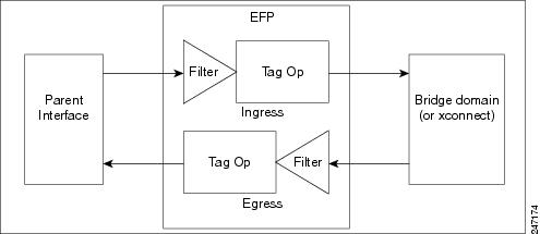
An EFP subinterface is configured to specify which traffic on ingress is vectored to that EFP. This is done by specifying a VLAN ID or QinQ tagging to match against on ingress. All traffic on ingress is compared to each EFP's matching criterion, and processed by that EFP if a match occurs. The processing performed by an EFP can change VLAN IDs, add or remove VLAN tags, and change ethertypes.
 Feedback