Implementing MPLS Layer 3 VPNs

A Multiprotocol Label Switching (MPLS) Layer 3 Virtual Private Network (VPN) consists of a set of sites that are interconnected by means of an MPLS provider core network. At each customer site, one or more customer edge (CE) routers attach to one or more provider edge (PE) routers.

This module provides the conceptual and configuration information for MPLS Layer 3 VPNs on Cisco IOS XR software.

Prerequisites for Implementing MPLS L3VPN

The following prerequisites are required to configure MPLS Layer 3 VPN:

  • To perform these configuration tasks, your Cisco IOS XR software system administrator must assign you to a user group associated with a task group that includes the corresponding command task IDs. All command task IDs are listed in individual command references and in the Cisco IOS XR Task ID Reference Guide.

  • If you suspect user group assignment is preventing you from using a command, contact your AAA administrator for assistance.

  • You must be in a user group associated with a task group that includes the proper task IDs for:

    • BGP commands

    • MPLS commands (generally)

    • MPLS Layer 3 VPN commands

  • To configure MPLS Layer 3 VPNs, routers must support MPLS forwarding and Forwarding Information Base (FIB).

MPLS L3VPN Restrictions

The following restrictions apply when configuring MPLS VPN Inter-AS with ASBRs exchanging IPv4 routes and MPLS labels:

  • For networks configured with eBGP multihop, a label switched path (LSP) must be configured between non adjacent routers.

  • Inter-AS supports IPv4 routes only. IPv6 is not supported.


Note


The physical interfaces that connect the BGP speakers must support FIB and MPLS.

Information About MPLS Layer 3 VPNs

To implement MPLS Layer 3 VPNs, you need to understand the following concepts:

MPLS L3VPN Overview

Before defining an MPLS VPN, VPN in general must be defined. A VPN is:

  • An IP-based network delivering private network services over a public infrastructure

  • A set of sites that are allowed to communicate with each other privately over the Internet or other public or private networks

Conventional VPNs are created by configuring a full mesh of tunnels or permanent virtual circuits (PVCs) to all sites in a VPN. This type of VPN is not easy to maintain or expand, as adding a new site requires changing each edge device in the VPN.

MPLS-based VPNs are created in Layer 3 and are based on the peer model. The peer model enables the service provider and the customer to exchange Layer 3 routing information. The service provider relays the data between the customer sites without customer involvement.

MPLS VPNs are easier to manage and expand than conventional VPNs. When a new site is added to an MPLS VPN, only the edge router of the service provider that provides services to the customer site needs to be updated.

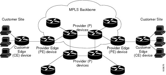
The components of the MPLS VPN are described as follows:

  • Provider (P) router—Router in the core of the provider network. P routers run MPLS switching and do not attach VPN labels to routed packets. VPN labels are used to direct data packets to the correct private network or customer edge router.

  • PE router—Router that attaches the VPN label to incoming packets based on the interface or subinterface on which they are received, and also attaches the MPLS core labels. A PE router attaches directly to a CE router.

  • Customer (C) router—Router in the Internet service provider (ISP) or enterprise network.

  • Customer edge (CE) router—Edge router on the network of the ISP that connects to the PE router on the network. A CE router must interface with a PE router.

This following figures shows a basic MPLS VPN topology.

Figure 1. Basic MPLS VPN Topology


MPLS L3VPN Benefits

MPLS L3VPN provides the following benefits:

  • Service providers can deploy scalable VPNs and deliver value-added services.

  • Connectionless service guarantees that no prior action is necessary to establish communication between hosts.

  • Centralized Service: Building VPNs in Layer 3 permits delivery of targeted services to a group of users represented by a VPN.

  • Scalability: Create scalable VPNs using connection-oriented, point-to-point overlays, Frame Relay, or ATM virtual connections.

  • Security: Security is provided at the edge of a provider network (ensuring that packets received from a customer are placed on the correct VPN) and in the backbone.

  • Integrated Quality of Service (QoS) support: QoS provides the ability to address predictable performance and policy implementation and support for multiple levels of service in an MPLS VPN.

  • Straightforward Migration: Service providers can deploy VPN services using a straightforward migration path.

  • Migration for the end customer is simplified. There is no requirement to support MPLS on the CE router and no modifications are required for a customer intranet.

How MPLS L3VPN Works

MPLS VPN functionality is enabled at the edge of an MPLS network. The PE router performs the following tasks:

  • Exchanges routing updates with the CE router

  • Translates the CE routing information into VPN version 4 (VPNv4) routes.

  • Exchanges VPNv4 and VPNv6 routes with other PE routers through the Multiprotocol Border Gateway Protocol (MP-BGP)

Virtual Routing and Forwarding Tables

Each VPN is associated with one or more VPN routing and forwarding (VRF) instances. A VRF defines the VPN membership of a customer site attached to a PE router. A VRF consists of the following components:

  • An IP version 4 (IPv4) unicast routing table

  • A derived FIB table

  • A set of interfaces that use the forwarding table

  • A set of rules and routing protocol parameters that control the information that is included in the routing table

These components are collectively called a VRF instance.

A one-to-one relationship does not necessarily exist between customer sites and VPNs. A site can be a member of multiple VPNs. However, a site can associate with only one VRF. A VRF contains all the routes available to the site from the VPNs of which it is a member.

Packet forwarding information is stored in the IP routing table and the FIB table for each VRF. A separate set of routing and FIB tables is maintained for each VRF. These tables prevent information from being forwarded outside a VPN and also prevent packets that are outside a VPN from being forwarded to a router within the VPN.

VPN Routing Information: Distribution

The distribution of VPN routing information is controlled through the use of VPN route target communities, implemented by BGP extended communities. VPN routing information is distributed as follows:

  • When a VPN route that is learned from a CE router is injected into a BGP, a list of VPN route target extended community attributes is associated with it. Typically, the list of route target community extended values is set from an export list of route targets associated with the VRF from which the route was learned.

  • An import list of route target extended communities is associated with each VRF. The import list defines route target extended community attributes that a route must have for the route to be imported into the VRF. For example, if the import list for a particular VRF includes route target extended communities A, B, and C, then any VPN route that carries any of those route target extended communities—A, B, or C—is imported into the VRF.

BGP Distribution of VPN Routing Information

A PE router can learn an IP prefix from the following sources:

  • A CE router by static configuration

  • An eBGP session with the CE router

  • A Routing Information Protocol (RIP) exchange with the CE router

  • Open Shortest Path First (OSPF), Enhanced Interior Gateway Routing Protocol (EIGRP), and RIP as Interior Gateway Protocols (IGPs)

The IP prefix is a member of the IPv4 address family. After the PE router learns the IP prefix, the PE converts it into the VPN-IPv4 prefix by combining it with a 64-bit route distinguisher. The generated prefix is a member of the VPN-IPv4 address family. It uniquely identifies the customer address, even if the customer site is using globally nonunique (unregistered private) IP addresses. The route distinguisher used to generate the VPN-IPv4 prefix is specified by the rd command associated with the VRF on the PE router.

BGP distributes reachability information for VPN-IPv4 prefixes for each VPN. BGP communication takes place at two levels:

  • Within the IP domain, known as an autonomous system.

  • Between autonomous systems.

PE to PE or PE to route reflector (RR) sessions are iBGP sessions, and PE to CE sessions are eBGP sessions. PE to CE eBGP sessions can be directly or indirectly connected (eBGP multihop).

BGP propagates reachability information for VPN-IPv4 prefixes among PE routers by the BGP protocol extensions (see RFC 2283, Multiprotocol Extensions for BGP-4), which define support for address families other than IPv4. Using the extensions ensures that the routes for a given VPN are learned only by other members of that VPN, enabling members of the VPN to communicate with each other.

MPLS Forwarding

Based on routing information stored in the VRF IP routing table and the VRF FIB table, packets are forwarded to their destination using MPLS.

A PE router binds a label to each customer prefix learned from a CE router and includes the label in the network reachability information for the prefix that it advertises to other PE routers. When a PE router forwards a packet received from a CE router across the provider network, it labels the packet with the label learned from the destination PE router. When the destination PE router receives the labeled packet, it pops the label and uses it to direct the packet to the correct CE router. Label forwarding across the provider backbone is based on either dynamic label switching or traffic engineered paths. A customer data packet carries two levels of labels when traversing the backbone:

  • The top label directs the packet to the correct PE router.

  • The second label indicates how that PE router should forward the packet to the CE router.

More labels can be stacked if other features are enabled. For example, if traffic engineering (TE) tunnels with fast reroute (FRR) are enabled, the total number of labels imposed in the PE is four (Layer 3 VPN, Label Distribution Protocol (LDP), TE, and FRR).

Automatic Route Distinguisher Assignment

To take advantage of iBGP load balancing, every network VRF must be assigned a unique route distinguisher. VRF requires a route distinguisher for BGP to distinguish between potentially identical prefixes received from different VPNs.

With thousands of routers in a network each supporting multiple VRFs, configuration and management of route distinguishers across the network can present a problem. Cisco IOS XR software simplifies this process by assigning unique route distinguisher to VRFs using the rd auto command.

To assign a unique route distinguisher for each router, you must ensure that each router has a unique BGP router-id. If so, the rd auto command assigns a Type 1 route distinguisher to the VRF using the following format: ip-address:number. The IP address is specified by the BGP router-id statement and the number (which is derived as an unused index in the 0 to 65535 range) is unique across theVRFs.

Finally, route distinguisher values are checkpointed so that route distinguisher assignment to VRF is persistent across failover or process restart. If an route distinguisher is explicitely configured for a VRF, this value is not overridden by the autoroute distinguisher.

MPLS L3VPN Major Components

An MPLS-based VPN network has three major components:

  • VPN route target communities—A VPN route target community is a list of all members of a VPN community. VPN route targets need to be configured for each VPN community member.

  • Multiprotocol BGP (MP-BGP) peering of the VPN community PE routers—MP-BGP propagates VRF reachability information to all members of a VPN community. MP-BGP peering needs to be configured in all PE routers within a VPN community.

  • MPLS forwarding—MPLS transports all traffic between all VPN community members across a VPN service-provider network.

A one-to-one relationship does not necessarily exist between customer sites and VPNs. A given site can be a member of multiple VPNs. However, a site can associate with only one VRF. A customer-site VRF contains all the routes available to the site from the VPNs of which it is a member

How to Implement MPLS Layer 3 VPNs

This section contains instructions for the following tasks:

Configuring the Core Network

Configuring the core network includes the following tasks:

Assessing the Needs of MPLS VPN Customers

Before configuring an MPLS VPN, the core network topology must be identified so that it can best serve MPLS VPN customers. Perform this task to identify the core network topology.

SUMMARY STEPS

  1. Identify the size of the network.
  2. Identify the routing protocols in the core.
  3. Determine if MPLS High Availability support is required.
  4. Determine if BGP load sharing and redundant paths are required.

DETAILED STEPS


Step 1

Identify the size of the network.

Identify the following to determine the number of routers and ports required:

  • How many customers will be supported?
  • How many VPNs are required for each customer?
  • How many virtual routing and forwarding (VRF) instances are there for each VPN?

Step 2

Identify the routing protocols in the core.

Determine which routing protocols are required in the core network.

Step 3

Determine if MPLS High Availability support is required.

MPLS VPN nonstop forwarding and graceful restart are supported on select routers and Cisco IOS XR software releases.

Step 4

Determine if BGP load sharing and redundant paths are required.

Determine if BGP load sharing and redundant paths in the MPLS VPN core are required.


Configuring Routing Protocols in the Core

To configure a routing protocol, see the .

Configuring MPLS in the Core

To enable MPLS on all routers in the core, you must configure a Label Distribution Protocol (LDP). You can use either of the following as an LDP:

  • MPLS LDP—See the Implementing MPLS Label Distribution Protocol chapter in the MPLS Configuration Guide for Cisco NCS 6000 Series Routers for configuration information.

  • MPLS Traffic Engineering Resource Reservation Protocol (RSVP)—See module in the MPLS Configuration Guide for Cisco NCS 6000 Series Routers for configuration information.

Determining if FIB Is Enabled in the Core

Forwarding Information Base (FIB) must be enabled on all routers in the core, including the provider edge (PE) routers. For information on how to determine if FIB is enabled, see the Implementing Cisco Express Forwarding module in the IP Addresses and Services Configuration Guide for Cisco NCS 6000 Series Routers.

Configuring Multiprotocol BGP on the PE Routers and Route Reflectors

Perform this task to configure multiprotocol BGP (MP-BGP) connectivity on the PE routers and route reflectors.

SUMMARY STEPS

  1. configure
  2. router bgp autonomous-system-number
  3. address-family vpnv4 unicast or address-family vpnv6 unicast
  4. neighbor ip-address remote-as autonomous-system-number
  5. address-family vpnv4 unicast or address-family vpnv6 unicast
  6. Use the commit or end command.

DETAILED STEPS


Step 1

configure

Example:

RP/0/RP0/CPU0:router# configure

Enters the XR Config mode.

Step 2

router bgp autonomous-system-number

Example:

RP/0/RP0/CPU0:router(config)# router bgp 120

Enters BGP configuration mode allowing you to configure the BGP routing process.

Step 3

address-family vpnv4 unicast or address-family vpnv6 unicast

Example:

RP/0/RP0/CPU0:router(config-bgp)# address-family vpnv4 unicast

Enters VPNv4 or VPNv6 address family configuration mode for the VPNv4 or VPNv6 address family.

Step 4

neighbor ip-address remote-as autonomous-system-number

Example:

RP/0/RP0/CPU0:router(config-bgp)# neighbor 172.168.40.24 remote-as 2002

Creates a neighbor and assigns it a remote autonomous system number.

Step 5

address-family vpnv4 unicast or address-family vpnv6 unicast

Example:

RP/0/RP0/CPU0:router(config-bgp-nbr)# address-family vpnv4 unicast

Enters VPNv4 or VPNv6 address family configuration mode for the VPNv4 or VPNv6 address family.

Step 6

Use the commit or end command.

commit - Saves the configuration changes and remains within the configuration session.

end - Prompts user to take one of these actions:

  • Yes - Saves configuration changes and exits the configuration session.
  • No - Exits the configuration session without committing the configuration changes.
  • Cancel - Remains in the configuration mode, without committing the configuration changes.

Connecting MPLS VPN Customers

To connect MPLS VPN customers to the VPN, perform the following tasks:

Defining VRFs on the PE Routers to Enable Customer Connectivity

Perform this task to define VPN routing and forwarding (VRF) instances.

SUMMARY STEPS

  1. configure
  2. vrf vrf-name
  3. address-family ipv4 unicast
  4. import route-policy policy-name
  5. import route-target [ as-number:nn | ip-address:nn ]
  6. export route-policy policy-name
  7. export route-target [ as-number:nn | ip-address:nn ]
  8. exit
  9. exit
  10. router bgp autonomous-system-number
  11. vrf vrf-name
  12. rd { as-number | ip-address | auto }
  13. Use the commit or end command.

DETAILED STEPS


Step 1

configure

Example:

RP/0/RP0/CPU0:router# configure

Enters XR Config mode.

Step 2

vrf vrf-name

Example:

RP/0/RP0/CPU0:router(config)# vrf vrf_1

Configures a VRF instance and enters VRF configuration mode.

Step 3

address-family ipv4 unicast

Example:

RP/0/RP0/CPU0:router(config-vrf)# address-family ipv4 unicast

Enters VRF address family configuration mode for the IPv4 address family.

Step 4

import route-policy policy-name

Example:

RP/0/RP0/CPU0:router(config-vrf-af)# import route-policy policy_A

Specifies a route policy that can be imported into the local VPN.

Step 5

import route-target [ as-number:nn | ip-address:nn ]

Example:

RP/0/RP0/CPU0:router(config-vrf-af)# import route-target 120:1

Allows exported VPN routes to be imported into the VPN if one of the route targets of the exported route matches one of the local VPN import route targets.

Step 6

export route-policy policy-name

Example:

RP/0/RP0/CPU0:router(config-vrf-af)# export route-policy policy_B

Specifies a route policy that can be exported from the local VPN.

Step 7

export route-target [ as-number:nn | ip-address:nn ]

Example:

RP/0/RP0/CPU0:router(config-vrf-af)# export route-target 120:2

Associates the local VPN with a route target. When the route is advertised to other provider edge (PE) routers, the export route target is sent along with the route as an extended community.

Step 8

exit

Example:

RP/0/RP0/CPU0:router(config-vrf-af)# exit

Exits VRF address family configuration mode and returns the router to VRF configuration mode.

Step 9

exit

Example:

RP/0/RP0/CPU0:router(config-vrf)# exit

Exits VRF configuration mode and returns the router to XR Config mode.

Step 10

router bgp autonomous-system-number

Example:

RP/0/RP0/CPU0:router(config)# router bgp 120

Enters BGP configuration mode allowing you to configure the BGP routing process.

Step 11

vrf vrf-name

Example:

RP/0/RP0/CPU0:router(config-bgp)# vrf vrf_1

Configures a VRF instance and enters VRF configuration mode for BGP routing.

Step 12

rd { as-number | ip-address | auto }

Example:

RP/0/RP0/CPU0:router(config-bgp-vrf)# rd auto

Automatically assigns a unique route distinguisher (RD) to vrf_1.

Step 13

Use the commit or end command.

commit - Saves the configuration changes and remains within the configuration session.

end - Prompts user to take one of these actions:

  • Yes - Saves configuration changes and exits the configuration session.
  • No - Exits the configuration session without committing the configuration changes.
  • Cancel - Remains in the configuration mode, without committing the configuration changes.

Configuring VRF Interfaces on PE Routers for Each VPN Customer

Perform this task to associate a VPN routing and forwarding (VRF) instance with an interface or a subinterface on the PE routers.


Note


You must remove IPv4/IPv6 addresses from an interface prior to assigning, removing, or changing an interface's VRF. If this is not done in advance, any attempt to change the VRF on an IP interface is rejected.

SUMMARY STEPS

  1. configure
  2. interface type interface-path-id
  3. vrf vrf-name
  4. ipv4 address ipv4-address mask
  5. Use the commit or end command.

DETAILED STEPS


Step 1

configure

Example:

RP/0/RP0/CPU0:router# configure

Enters XR Config mode.

Step 2

interface type interface-path-id

Example:

RP/0/RP0/CPU0:router(config)# interface TenGigE 0/3/0/0

Enters interface configuration mode.

Step 3

vrf vrf-name

Example:

RP/0/RP0/CPU0:router(config-if)# vrf vrf_A

Configures a VRF instance and enters VRF configuration mode.

Step 4

ipv4 address ipv4-address mask

Example:

RP/0/RP0/CPU0:router(config-if)# ipv4 address 192.168.1.27 255.255.255.0

Configures a primary IPv4 address for the specified interface.

Step 5

Use the commit or end command.

commit - Saves the configuration changes and remains within the configuration session.

end - Prompts user to take one of these actions:

  • Yes - Saves configuration changes and exits the configuration session.
  • No - Exits the configuration session without committing the configuration changes.
  • Cancel - Remains in the configuration mode, without committing the configuration changes.

Configuring BGP as the Routing Protocol Between the PE and CE Routers

Perform this task to configure PE-to-CE routing sessions using BGP.

SUMMARY STEPS

  1. configure
  2. router bgp autonomous-system-number
  3. bgp router-id { ip-address }
  4. vrf vrf-name
  5. address-family ipv4 unicast
  6. label mode per-ce
  7. Do one of the following:
    • redistribute connected [ metric metric-value ] [ route-policy route-policy-name ]
    • redistribute ospf process-id [ match { external [ 1 | 2 ] | internal | nssa-external [ 1 | 2 ] } ] [ metric metric-value ] [route-policy route-policy-name ]
    • redistribute static [ metric metric-value ] [ route-policy route-policy-name ]
  8. aggregate-address address/mask-length [as-set ] [as-confed-set ] [summary-only ] [route-policy route-policy-name]
  9. network {ip-address/prefix-length | ip-address mask } [ route-policy route-policy-name ]
  10. exit
  11. neighbor ip-address
  12. remote-as autonomous-system-number
  13. password { clear | encrypted } password
  14. ebgp-multihop [ ttl-value ]
  15. address-family ipv4 unicast
  16. allowas-in [ as-occurrence-number ]
  17. route-policy route-policy-name in
  18. route-policy route-policy-name out
  19. Use the commit or end command.

DETAILED STEPS


Step 1

configure

Example:

RP/0/RP0/CPU0:router# configure

Enters XR Config mode.

Step 2

router bgp autonomous-system-number

Example:

RP/0/RP0/CPU0:router(config)# router bgp 120

Enters Border Gateway Protocol (BGP) configuration mode allowing you to configure the BGP routing process.

Step 3

bgp router-id { ip-address }

Example:

RP/0/RP0/CPU0:router(config-bgp)# bgp router-id 192.168.70.24

Configures the local router with a router ID of 192.168.70.24.

Step 4

vrf vrf-name

Example:

RP/0/RP0/CPU0:router(config-bgp)# vrf vrf_1

Configures a VPN routing and forwarding (VRF) instance and enters VRF configuration mode for BGP routing.

Step 5

address-family ipv4 unicast

Example:

RP/0/RP0/CPU0:router(config-bgp-vrf)# address-family ipv4 unicast

Enters VRF address family configuration mode for the IPv4 address family.

Step 6

label mode per-ce

Example:

RP/0/RP0/CPU0:router(config-bgp-vrf-af)# label mode per-ce

Sets the MPLS VPN label allocation mode for each customer edge (CE) label mode allowing the provider edge (PE) router to allocate one label for every immediate next-hop.

Step 7

Do one of the following:

  • redistribute connected [ metric metric-value ] [ route-policy route-policy-name ]
  • redistribute ospf process-id [ match { external [ 1 | 2 ] | internal | nssa-external [ 1 | 2 ] } ] [ metric metric-value ] [route-policy route-policy-name ]
  • redistribute static [ metric metric-value ] [ route-policy route-policy-name ]
Example:

RP/0/RP0/CPU0:router(config-bgp-vrf-af)# redistribute connected

Causes routes to be redistributed into BGP. The routes that can be redistributed into BGP are:

  • Connected
  • Intermediate System-to-Intermediate System (IS-IS)
  • Open Shortest Path First (OSPF)
  • Static

Step 8

aggregate-address address/mask-length [as-set ] [as-confed-set ] [summary-only ] [route-policy route-policy-name]

Example:

RP/0/RP0/CPU0:router(config-bgp-vrf-af)# aggregate-address 10.0.0.0/8 as-set

Creates an aggregate address. The path advertised for this route is an autonomous system set consisting of all elements contained in all paths that are being summarized.

  • The as-set keyword generates autonomous system set path information and community information from contributing paths.
  • The as-confed-set keyword generates autonomous system confederation set path information from contributing paths.
  • The summary-only keyword filters all more specific routes from updates.
  • The route-policy route-policy-name keyword and argument specify the route policy used to set the attributes of the aggregate route.

Step 9

network {ip-address/prefix-length | ip-address mask } [ route-policy route-policy-name ]

Example:

RP/0/RP0/CPU0:router(config-bgp-vrf-af)# network 172.20.0.0/16 

Configures the local router to originate and advertise the specified network.

Step 10

exit

Example:

RP/0/RP0/CPU0:router(config-bgp-vrf-af)# exit

Exits VRF address family configuration mode and returns the router to VRF configuration mode for BGP routing.

Step 11

neighbor ip-address

Example:

RP/0/RP0/CPU0:router(config-bgp-vrf)# neighbor 172.168.40.24

Places the router in VRF neighbor configuration mode for BGP routing and configures the neighbor IP address 172.168.40.24 as a BGP peer.

Step 12

remote-as autonomous-system-number

Example:

RP/0/RP0/CPU0:router(config-bgp-vrf-nbr)# remote-as 2002

Creates a neighbor and assigns it a remote autonomous system number.

Step 13

password { clear | encrypted } password

Example:

RP/0/RP0/CPU0:router(config-bgp-vrf-nbr)# password clear pswd123

Configures neighbor 172.168.40.24 to use MD5 authentication with the password pswd123.

Step 14

ebgp-multihop [ ttl-value ]

Example:

RP/0/RP0/CPU0:router(config-bgp-vrf-nbr)# ebgp-multihop

Allows a BGP connection to neighbor 172.168.40.24.

Step 15

address-family ipv4 unicast

Example:

RP/0/RP0/CPU0:router(config-bgp-vrf-nbr)# address-family ipv4 unicast

Enters VRF neighbor address family configuration mode for BGP routing.

Step 16

allowas-in [ as-occurrence-number ]

Example:

RP/0/RP0/CPU0:router(config-bgp-vrf-nbr-af)# allowas-in 3

Replaces the neighbor autonomous system number (ASN) with the PE ASN in the AS path three times.

Step 17

route-policy route-policy-name in

Example:

RP/0/RP0/CPU0:router(config-bgp-vrf-nbr-af)# route-policy In-Ipv4 in

Applies the In-Ipv4 policy to inbound IPv4 unicast routes.

Step 18

route-policy route-policy-name out

Example:

RP/0/RP0/CPU0:router(config-bgp-vrf-nbr-af)# route-policy In-Ipv4 in

Applies the In-Ipv4 policy to outbound IPv4 unicast routes.

Step 19

Use the commit or end command.

commit - Saves the configuration changes and remains within the configuration session.

end - Prompts user to take one of these actions:

  • Yes - Saves configuration changes and exits the configuration session.
  • No - Exits the configuration session without committing the configuration changes.
  • Cancel - Remains in the configuration mode, without committing the configuration changes.

Configuring RIPv2 as the Routing Protocol Between the PE and CE Routers

Perform this task to configure provider edge (PE)-to-customer edge (CE) routing sessions using Routing Information Protocol version 2 (RIPv2).

SUMMARY STEPS

  1. configure
  2. router rip
  3. vrf vrf-name
  4. interface type instance
  5. site-of-origin { as-number : number | ip-address : number }
  6. exit
  7. Do one of the following:
    • redistribute bgp as-number [ [ external | internal | local ] [ route-policy name ]
    • redistribute connected [ route-policy name ]
    • redistribute isis process-id [ level-1 | level-1-2 | level-2 ] [ route-policy name ]
    • redistribute eigrp as-number [ route-policy name ]
    • redistribute ospf process-id [ match { external [ 1 | 2 ] | internal | nssa-external [ 1 | 2 ] } ] [ route-policy name ]
    • redistribute static [ route-policy name ]
  8. Use the commit or end command.

DETAILED STEPS


Step 1

configure

Example:

RP/0/RP0/CPU0:router# configure

Enters XR Config mode.

Step 2

router rip

Example:

RP/0/RP0/CPU0:router(config)# router rip

Enters the Routing Information Protocol (RIP) configuration mode allowing you to configure the RIP routing process.

Step 3

vrf vrf-name

Example:

RP/0/RP0/CPU0:router(config-rip)# vrf vrf_1

Configures a VPN routing and forwarding (VRF) instance and enters VRF configuration mode for RIP routing.

Step 4

interface type instance

Example:

RP/0/RP0/CPU0:router(config-rip-vrf)# interface TenGigE 0/3/0/0

Enters VRF interface configuration mode.

Step 5

site-of-origin { as-number : number | ip-address : number }

Example:

RP/0/RP0/CPU0:router(config-rip-vrf-if)# site-of-origin 200:1

Identifies routes that have originated from a site so that the re-advertisement of that prefix back to the source site can be prevented. Uniquely identifies the site from which a PE router has learned a route.

Step 6

exit

Example:

RP/0/RP0/CPU0:router(config-rip-vrf-if)# exit

Exits VRF interface configuration mode, and returns the router to VRF configuration mode for RIP routing.

Step 7

Do one of the following:

  • redistribute bgp as-number [ [ external | internal | local ] [ route-policy name ]
  • redistribute connected [ route-policy name ]
  • redistribute isis process-id [ level-1 | level-1-2 | level-2 ] [ route-policy name ]
  • redistribute eigrp as-number [ route-policy name ]
  • redistribute ospf process-id [ match { external [ 1 | 2 ] | internal | nssa-external [ 1 | 2 ] } ] [ route-policy name ]
  • redistribute static [ route-policy name ]
Example:

RP/0/RP0/CPU0:router(config-rip-vrf)# redistribute connected

Causes routes to be redistributed into RIP. The routes that can be redistributed into RIP are:

  • Border Gateway Protocol (BGP)
  • Connected
  • Enhanced Interior Gateway Routing Protocol (EIGRP)
  • Intermediate System-to-Intermediate System (IS-IS)
  • Open Shortest Path First (OSPF)
  • Static

Step 8

Use the commit or end command.

commit - Saves the configuration changes and remains within the configuration session.

end - Prompts user to take one of these actions:

  • Yes - Saves configuration changes and exits the configuration session.
  • No - Exits the configuration session without committing the configuration changes.
  • Cancel - Remains in the configuration mode, without committing the configuration changes.

Configuring Static Routes Between the PE and CE Routers

Perform this task to configure provider edge (PE)-to-customer edge (CE) routing sessions that use static routes.


Note


You must remove IPv4/IPv6 addresses from an interface prior to assigning, removing, or changing an interface's VRF. If this is not done in advance, any attempt to change the VRF on an IP interface is rejected.

SUMMARY STEPS

  1. configure
  2. router static
  3. vrf vrf-name
  4. address-family ipv4 unicast
  5. prefix/mask [ vrf vrf-name ] { ip-address | type interface-path-id }
  6. prefix/mask [vrf vrf-name] bfd fast-detect
  7. Use the commit or end command.

DETAILED STEPS


Step 1

configure

Example:

RP/0/RP0/CPU0:router# configure

Enters XR Config mode.

Step 2

router static

Example:

RP/0/RP0/CPU0:router(config)# router static

Enters static routing configuration mode allowing you to configure the static routing process.

Step 3

vrf vrf-name

Example:

RP/0/RP0/CPU0:router(config-static)# vrf vrf_1

Configures a VPN routing and forwarding (VRF) instance and enters VRF configuration mode for static routing.

Step 4

address-family ipv4 unicast

Example:

RP/0/RP0/CPU0:router(config-static-vrf)# address-family ipv4 unicast

Enters VRF address family configuration mode for the IPv4 address family.

Step 5

prefix/mask [ vrf vrf-name ] { ip-address | type interface-path-id }

Example:

RP/0/RP0/CPU0:router(config-static-vrf-afi)# 172.168.40.24/24 vrf vrf_1 10.1.1.1

Assigns the static route to vrf_1.

Step 6

prefix/mask [vrf vrf-name] bfd fast-detect

Example:

RP/0/RP0/CPU0:router(config-static-vrf-afi)# 172.168.40.24/24 vrf vrf_1 bfd fast-detect

Enables bidirectional forwarding detection (BFD) to detect failures in the path between adjacent forwarding engines.

This option is available is when the forwarding router address is specified in Step 5 .

Step 7

Use the commit or end command.

commit - Saves the configuration changes and remains within the configuration session.

end - Prompts user to take one of these actions:

  • Yes - Saves configuration changes and exits the configuration session.
  • No - Exits the configuration session without committing the configuration changes.
  • Cancel - Remains in the configuration mode, without committing the configuration changes.

Configuring OSPF as the Routing Protocol Between the PE and CE Routers

Perform this task to configure provider edge (PE)-to-customer edge (CE) routing sessions that use Open Shortest Path First (OSPF).

SUMMARY STEPS

  1. configure
  2. router ospf process-name
  3. vrf vrf-name
  4. router-id {router-id | type interface-path-id}
  5. Do one of the following:
    • redistribute bgp process-id [metric metric-value ] [metric-type {1 | 2 }] [route-policy policy-name ] [ tag tag-value ]
    • redistribute connected [metric metric-value ] [metric-type {1 | 2 }] [route-policy policy-name ] [tag tag-value ]
    • redistribute ospf process-id [match {external [1 | 2 ] | internal | nssa-external [1 | 2 ]}] [metric metric-value ] [metric-type {1 | 2 }] [route-policy policy-name ] [tag tag-value ]
    • redistribute static [metric metric-value ] [metric-type {1 | 2 }] [route-policy policy-name ] [tag tag-value ]
    • redistribute eigrp process-id [match {external [1 | 2 ] | internal | nssa-external [1 | 2 ]]} [metric metric-value ] [metric-type {1 | 2 }] [route-policy policy-name ] [tag tag-value ]
    • redistribute rip [metric metric-value ] [metric-type {1 | 2 }] [route-policy policy-name ] [tag tag-value ]
  6. area area-id
  7. interface type interface-path-id
  8. Use the commit or end command.

DETAILED STEPS


Step 1

configure

Example:

RP/0/RP0/CPU0:router# configure

Enters XR Config mode.

Step 2

router ospf process-name

Example:

RP/0/RP0/CPU0:router(config)# router ospf 109

Enters OSPF configuration mode allowing you to configure the OSPF routing process.

Step 3

vrf vrf-name

Example:

RP/0/RP0/CPU0:router(config-ospf)# vrf vrf_1

Configures a VPN routing and forwarding (VRF) instance and enters VRF configuration mode for OSPF routing.

Step 4

router-id {router-id | type interface-path-id}

Example:

RP/0/RP0/CPU0:router(config-ospf-vrf)# router-id 172.20.10.10

Configures the router ID for the OSPF routing process.

Step 5

Do one of the following:

  • redistribute bgp process-id [metric metric-value ] [metric-type {1 | 2 }] [route-policy policy-name ] [ tag tag-value ]
  • redistribute connected [metric metric-value ] [metric-type {1 | 2 }] [route-policy policy-name ] [tag tag-value ]
  • redistribute ospf process-id [match {external [1 | 2 ] | internal | nssa-external [1 | 2 ]}] [metric metric-value ] [metric-type {1 | 2 }] [route-policy policy-name ] [tag tag-value ]
  • redistribute static [metric metric-value ] [metric-type {1 | 2 }] [route-policy policy-name ] [tag tag-value ]
  • redistribute eigrp process-id [match {external [1 | 2 ] | internal | nssa-external [1 | 2 ]]} [metric metric-value ] [metric-type {1 | 2 }] [route-policy policy-name ] [tag tag-value ]
  • redistribute rip [metric metric-value ] [metric-type {1 | 2 }] [route-policy policy-name ] [tag tag-value ]
Example:

RP/0/RP0/CPU0:router(config-ospf-vrf)# redistribute connected

Causes routes to be redistributed into OSPF. The routes that can be redistributed into OSPF are:

  • Border Gateway Protocol (BGP)
  • Connected
  • Enhanced Interior Gateway Routing Protocol (EIGRP)
  • OSPF
  • Static
  • Routing Information Protocol (RIP)

Step 6

area area-id

Example:

RP/0/RP0/CPU0:router(config-ospf-vrf)# area 0

Configures the OSPF area as area 0.

Step 7

interface type interface-path-id

Example:

RP/0/RP0/CPU0:router(config-ospf-vrf-ar)# interface TenGigE 0/3/0/0

Associates interface TenGigE 0/3/0/0 with area 0.

Step 8

Use the commit or end command.

commit - Saves the configuration changes and remains within the configuration session.

end - Prompts user to take one of these actions:

  • Yes - Saves configuration changes and exits the configuration session.
  • No - Exits the configuration session without committing the configuration changes.
  • Cancel - Remains in the configuration mode, without committing the configuration changes.

Configuring EIGRP as the Routing Protocol Between the PE and CE Routers

Perform this task to configure provider edge (PE)-to-customer edge (CE) routing sessions that use Enhanced Interior Gateway Routing Protocol (EIGRP).

Using EIGRP between the PE and CE routers allows you to transparently connect EIGRP customer networks through an MPLS-enable Border Gateway Protocol (BGP) core network so that EIGRP routes are redistributed through the VPN across the BGP network as internal BGP (iBGP) routes.

Before you begin

BGP is configured in the network. See the Implementing BGP module in the Routing Configuration Guide for Cisco NCS 6000 Series Routers


Note


You must remove IPv4/IPv6 addresses from an interface prior to assigning, removing, or changing an interface's VRF. If this is not done in advance, any attempt to change the VRF on an IP interface is rejected.


SUMMARY STEPS

  1. configure
  2. router eigrp as-number
  3. vrf vrf-name
  4. address-family ipv4
  5. router-id router-id
  6. autonomous-system as-number
  7. default-metric bandwidth delay reliability loading mtu
  8. redistribute { { bgp | connected | isis | ospf | rip | static } [ as-number | instance-name ] } [ route-policy name ]
  9. interface type interface-path-id
  10. site-of-origin { as-number:number | ip-address : number }
  11. Use the commit or end command.

DETAILED STEPS


Step 1

configure

Example:

RP/0/RP0/CPU0:router# configure

Enters XR Config mode.

Step 2

router eigrp as-number

Example:

RP/0/RP0/CPU0:router(config)# router eigrp 24

Enters EIGRP configuration mode allowing you to configure the EIGRP routing process.

Step 3

vrf vrf-name

Example:

RP/0/RP0/CPU0:router(config-eigrp)# vrf vrf_1

Configures a VPN routing and forwarding (VRF) instance and enters VRF configuration mode for EIGRP routing.

Step 4

address-family ipv4

Example:

RP/0/RP0/CPU0:router(config-eigrp-vrf)# address family ipv4

Enters VRF address family configuration mode for the IPv4 address family.

Step 5

router-id router-id

Example:

RP/0/RP0/CPU0:router(config-eigrp-vrf-af)# router-id 172.20.0.0

Configures the router ID for the Enhanced Interior Gateway Routing Protocol (EIGRP) routing process.

Step 6

autonomous-system as-number

Example:

RP/0/RP0/CPU0:router(config-eigrp-vrf-af)# autonomous-system 6

Configures the EIGRP routing process to run within a VRF.

Step 7

default-metric bandwidth delay reliability loading mtu

Example:

RP/0/RP0/CPU0:router(config-eigrp-vrf-af)# default-metric 100000 4000 200 45 4470

Sets the metrics for an EIGRP.

Step 8

redistribute { { bgp | connected | isis | ospf | rip | static } [ as-number | instance-name ] } [ route-policy name ]

Example:

RP/0/RP0/CPU0:router(config-eigrp-vrf-af)# redistribute connected

Causes connected routes to be redistributed into EIGRP.

Step 9

interface type interface-path-id

Example:

RP/0/RP0/CPU0:router(config-eigrp-vrf-af)# interface TenGigE 0/3/0/0

Associates interface TenGigE 0/3/0/0 with the EIGRP routing process.

Step 10

site-of-origin { as-number:number | ip-address : number }

Example:

RP/0/RP0/CPU0:router(config-eigrp-vrf-af-if)# site-of-origin 201:1

Configures site of origin (SoO) on interface TenGigE 0/3/0/0.

Step 11

Use the commit or end command.

commit - Saves the configuration changes and remains within the configuration session.

end - Prompts user to take one of these actions:

  • Yes - Saves configuration changes and exits the configuration session.
  • No - Exits the configuration session without committing the configuration changes.
  • Cancel - Remains in the configuration mode, without committing the configuration changes.

Configuring EIGRP Redistribution in the MPLS VPN

Perform this task for every provider edge (PE) router that provides VPN services to enable Enhanced Interior Gateway Routing Protocol (EIGRP) redistribution in the MPLS VPN.

Before you begin
The metric can be configured in the route-policy configuring using the redistribute command (or configured with the default-metric command). If an external route is received from another EIGRP autonomous system or a non-EIGRP network without a configured metric, the route is not installed in the EIGRP database. If an external route is received from another EIGRP autonomous system or a non-EIGRP network without a configured metric, the route is not advertised to the CE router. See the Implementing EIGRPmodule in the Routing Configuration Guide for Cisco NCS 6000 Series Routers.

Restriction


Redistribution between native EIGRP VPN routing and forwarding (VRF) instances is not supported. This behavior is designed.

SUMMARY STEPS

  1. configure
  2. router eigrp as-number
  3. vrf vrf-name
  4. address-family ipv4
  5. redistribute bgp [as-number ] [route-policy policy-name ]
  6. Use the commit or end command.

DETAILED STEPS


Step 1

configure

Example:

RP/0/RP0/CPU0:router# configure

Enters XR Config mode.

Step 2

router eigrp as-number

Example:

RP/0/RP0/CPU0:router(config)# router eigrp 24

Enters EIGRP configuration mode allowing you to configure the EIGRP routing process.

Step 3

vrf vrf-name

Example:

RP/0/RP0/CPU0:router(config-eigrp)# vrf vrf_1

Configures a VRF instance and enters VRF configuration mode for EIGRP routing.

Step 4

address-family ipv4

Example:

RP/0/RP0/CPU0:router(config-eigrp-vrf)# address family ipv4

Enters VRF address family configuration mode for the IPv4 address family.

Step 5

redistribute bgp [as-number ] [route-policy policy-name ]

Example:

RP/0/RP0/CPU0:router(config-eigrp-vrf-af)# redistribute bgp 24 route-policy policy_A

Causes Border Gateway Protocol (BGP) routes to be redistributed into EIGRP.

Step 6

Use the commit or end command.

commit - Saves the configuration changes and remains within the configuration session.

end - Prompts user to take one of these actions:

  • Yes - Saves configuration changes and exits the configuration session.
  • No - Exits the configuration session without committing the configuration changes.
  • Cancel - Remains in the configuration mode, without committing the configuration changes.

Verifying the MPLS Layer 3 VPN Configuration

Perform this task to verify the MPLS Layer 3 VPN configuration.

SUMMARY STEPS

  1. show running-config router bgp as-number vrf vrf-name
  2. show running-config routes
  3. show ospf vrf vrf-name database
  4. show running-config router bgp as-number vrf vrf-name neighbor ip-address
  5. show bgp vrf vrf-name summary
  6. show bgp vrf vrf-name neighbors ip-address
  7. show bgp vrf vrf-name
  8. show route vrf vrf-name ip-address
  9. show bgp vpn unicast summary
  10. show running-config router isis
  11. show running-config mpls
  12. show isis adjacency
  13. show mpls ldp forwarding
  14. show bgp vpnv4 unicast or show bgp vrf vrf-name
  15. show bgp vrf vrf-name imported-routes
  16. show route vrf vrf-name ip-address
  17. show cef vrf vrf-name ip-address
  18. show cef vrf vrf-name ip-address location node-id
  19. show bgp vrf vrf-name ip-address
  20. show ospf vrf vrf-name database

DETAILED STEPS


Step 1

show running-config router bgp as-number vrf vrf-name

Example:


RP/0/RP0/CPU0:router# show running-config router bgp 3 vrf vrf_A

Displays the specified VPN routing and forwarding (VRF) content of the currently running configuration.

Step 2

show running-config routes

Example:


RP/0/RP0/CPU0:router# show running-config routes

Displays the Open Shortest Path First (OSPF) routes table in the currently running configuration.

Step 3

show ospf vrf vrf-name database

Example:


RP/0/RP0/CPU0:router# show ospf vrf vrf_A database

Displays lists of information related to the OSPF database for a specified VRF.

Step 4

show running-config router bgp as-number vrf vrf-name neighbor ip-address

Example:


RP/0/RP0/CPU0:router# show running-config router bgp 3 vrf vrf_A neighbor 172.168.40.24

Displays the Border Gateway Protocol (BGP) VRF neighbor content of the currently running configuration.

Step 5

show bgp vrf vrf-name summary

Example:


RP/0/RP0/CPU0:router# show bgp vrf vrf_A summary

Displays the status of the specified BGP VRF connections.

Step 6

show bgp vrf vrf-name neighbors ip-address

Example:


RP/0/RP0/CPU0:router# show bgp vrf vrf_A neighbors 172.168.40.24

Displays information about BGP VRF connections to the specified neighbors.

Step 7

show bgp vrf vrf-name

Example:


RP/0/RP0/CPU0:router# show bgp vrf vrf_A

Displays information about a specified BGP VRF.

Step 8

show route vrf vrf-name ip-address

Example:


RP/0/RP0/CPU0:router# show route vrf vrf_A 10.0.0.0

Displays the current routes in the Routing Information Base (RIB) for a specified VRF.

Step 9

show bgp vpn unicast summary

Example:


RP/0/RP0/CPU0:router# show bgp vpn unicast summary

Displays the status of all BGP VPN unicast connections.

Step 10

show running-config router isis

Example:


RP/0/RP0/CPU0:router# show running-config router isis

Displays the Intermediate System-to-Intermediate System (IS-IS) content of the currently running configuration.

Step 11

show running-config mpls

Example:


RP/0/RP0/CPU0:router# show running-config mpls

Displays the MPLS content of the currently running-configuration.

Step 12

show isis adjacency

Example:


RP/0/RP0/CPU0:router# show isis adjacency

Displays IS-IS adjacency information.

Step 13

show mpls ldp forwarding

Example:


RP/0/RP0/CPU0:router# show mpls ldp forwarding

Displays the Label Distribution Protocol (LDP) forwarding state installed in MPLS forwarding.

Step 14

show bgp vpnv4 unicast or show bgp vrf vrf-name

Example:


RP/0/RP0/CPU0:router# show bgp vpnv4 unicast

Displays entries in the BGP routing table for VPNv4 or VPNv6 unicast addresses.

Step 15

show bgp vrf vrf-name imported-routes

Example:


RP/0/RP0/CPU0:router# show bgp vrf vrf_A imported-routes

Displays BGP information for routes imported into specified VRF instances.

Step 16

show route vrf vrf-name ip-address

Example:


RP/0/RP0/CPU0:router# show route vrf vrf_A 10.0.0.0

Displays the current specified VRF routes in the RIB.

Step 17

show cef vrf vrf-name ip-address

Example:


RP/0/RP0/CPU0:router# show cef vrf vrf_A 10.0.0.1

Displays the IPv4 Cisco Express Forwarding (CEF) table for a specified VRF.

Step 18

show cef vrf vrf-name ip-address location node-id

Example:


RP/0/RP0/CPU0:router# show cef vrf vrf_A 10.0.0.1 location 0/1/cpu0

Displays the IPv4 CEF table for a specified VRF and location.

Step 19

show bgp vrf vrf-name ip-address

Example:


RP/0/RP0/CPU0:router# show bgp vrf vrf_A 10.0.0.0

Displays entries in the BGP routing table for VRF vrf_A.

Step 20

show ospf vrf vrf-name database

Example:


RP/0/RP0/CPU0:router# show ospf vrf vrf_A database

Displays lists of information related to the OSPF database for a specified VRF.


Configuration Examples for Implementing MPLS Layer 3 VPNs

The following section provides sample configurations for MPLS L3VPN features:

Configuring an MPLS VPN Using BGP: Example

The following example shows the configuration for an MPLS VPN using BGP on “vrf vpn1”:

address-family ipv4 unicast
    import route-target 
      100:1
    !
    export route-target 
      100:1
    !
  !
!
route-policy pass-all
  pass
end-policy
!
interface Loopback0
  ipv4 address 10.0.0.1 255.255.255.255
!
interface TenGigE 0/1/0/0
  vrf vpn1
  ipv4 address 10.0.0.2 255.0.0.0
!
interface TenGigE 0/1/0/1
  ipv4 address 10.0.0.1 255.0.0.0
!
router ospf 100
  area 100
    interface loopback0
    interface TenGigE 0/1/0/1
  !
!
router bgp 100
  address-family vpnv4 unicast
  retain route-target route-policy policy1
  neighbor 10.0.0.3
    remote-as 100
    update-source Loopback0
    address-family vpnv4 unicast
  !        
  vrf vpn1
    rd 100:1
    address-family ipv4 unicast
      redistribute connected
    ! 
    neighbor 10.0.0.1 
      remote-as 200
      address-family ipv4 unicast
        as-override
        route-policy pass-all in
        route-policy pass-all out
      !
      advertisement-interval 5
    !
  !
!
mpls ldp
  route-id looback0
  interface TenGigE 0/1/0/1
!

Configuring the Routing Information Protocol on the PE Router: Example

The following example shows the configuration for the RIP on the PE router:

vrf vpn1
  address-family ipv4 unicast
    import route-target 
      100:1
    !
    export route-target 
      100:1
    !
  !
!
route-policy pass-all
  pass
end-policy
!

interface TenGigE 0/1/0/0
  vrf vpn1
  ipv4 address 10.0.0.2 255.0.0.0
!

router rip
 vrf vpn1
  interface TenGigE 0/1/0/0
  !
  timers basic 30 90 90 120
  redistribute bgp 100
  default-metric 3
  route-policy pass-all in
 !

Configuring the PE Router Using EIGRP: Example

The following example shows the configuration for the Enhanced Interior Gateway Routing Protocol (EIGRP) on the PE router:

Router eigrp 10
 vrf VRF1
  address-family ipv4
   router-id 10.1.1.2
   default-metric 100000 2000 255 1 1500
   as 62
   redistribute bgp 2000
   interface Loopback0
   !
   interface TenGigE 0/6/0/0

Pseudowire Headend

Pseudowire Headend (PWHE) feature allows termination of access pseudowires (PWs) into a Layer 3 (VRF or global) domain or into a Layer 2 domain. PWs provide an easy and scalable mechanism for tunneling customer traffic into a common IP/MPLS network infrastructure. PWHE allows customers to provision features such as quality of service (QoS), access lists (ACL), lawful intercept (LI), bidirectional forwarding detection (BFD), unicast reverse path forwarding (uRPF), NetFlow, and L3VPN on a per PWHE interface basis, on a service Provider Edge (PE) router.

Pseudowires (PWs) enable payloads to be transparently carried across IP/MPLS packet-switched networks (PSNs). Service providers are now extending PW connectivity into the access and aggregation regions of their networks. PWs are regarded as simple and manageable lightweight tunnels for returning customer traffic into core networks.

PWHE cross-connects to a pseudowire neighbor, which is reachable through recursive as well as non-recursive prefix. The reachability through recursive prefix is through introduction of BGP RFC3107 support on the Cisco NCS 6000 Series Router. Consider the following network topology for an example scenario.
Figure 2. Pseudowire Network


For PWHE cross-connect configuration, interconnectivity between A-PE (Access Provider Edge) and S-PE (Service Provider Edge) is through BGP RFC3107 that distributes MPLS labels along with IP prefixes. The customer network can avoid using an IGP to provide connectivity to the S-PE device, which is outside the customer's autonomous system.

For all practical purposes, the PWHE interface is treated like any other existing L3 interface. PWs operate in one of the following modes:
  • Bridged interworking (VC type 4 or VC type 5) mode

  • IP interworking mode (VC type 11)

With VC type 4 and VC type 5, PWs carry customer Ethernet frames (tagged or untagged) with IP payload. Thus, an S-PE device must perform ARP resolution for customer IP addresses learned over the PWHE. With VC type 4 (VLAN tagged) and VC type 5 (Ethernet port/raw), PWHE acts as a broadcast interface. Whereas with VC type 11 (IP Interworking), PWHE acts as a point-to-point interface. Therefore there are two types of PWHE interface:
  • PW-Ether (for VC type 4 and 5)

  • PW-IW (for VC type 11)

These PWs can terminate into a VRF or the IP global table on S-PE.

Benefits of PWHE

Some of the benefits of implementing PWHE are:

  • Dissociates the customer facing interface (CFI) of the S-PE from the underlying physical transport media of the access or aggregation network.

  • Reduces capex in the access or aggregation network and S-PE.

  • Distributes and scales the customer facing Layer 2 UNI interface set.

  • Implements a uniform method of OAM functionality.

  • Enables providers to extend or expand the Layer 3 service footprints.

  • Provides a method of terminating customer traffic into a next generation network (NGN).

Generic Interface List

A generic interface list contains a list of physical or bundle interfaces that is used in a PW-HE connection.

The generic interface list supports only main interfaces, and not sub-interfaces. The generic interface list is bi-directional and restricts both receive and transmit interfaces on access-facing line cards. The generic interface list has no impact on the core-facing side.

A generic interface list is used to limit the resources allocated for a PWHE interface to the set of interfaces specified in the list.

Only the S-PE is aware of the generic interface list and expects that the PWHE packets arrive on only line cards with generic interface list members on it. If packets arrive at the line card without generic interface list members on it, they are dropped.

Configure Pseudowire Headend

The Pseudowire Headend (PWHE) is created by configuring the pw-ether main interface, pw-ether subinterface, or pw-iw interface. The available PWHE types are pw-ether main interfaces, subinterfaces, and pw-iw interfaces. Unless specified otherwise, the term interface is applicable for pw-ether main interfaces, subinterfaces, and pw-iw interfaces.

For the PWHE to be functional, the cross-connect has to be configured completely. Configuring other Layer 3 (L3) parameters, such as VRF and IP addresses, are optional for the PWHE to be functional. However, the L3 features are required for the Layer 3 services to be operational; that is, for PW L3 termination. PWHE supports both IPv4 and IPv6 addresses.

PWHE Configuration Restrictions

These configuration restrictions are applicable for PWHE:

  • The generic interface list members must be the superset of the equal-cost multi-path routing (ECMP) path list to the A-PE.

  • Only eight generic interface lists are supported per A-PE neighbor address.

  • Eight Layer 3 links per generic interface list are supported.

  • Each generic interface list can have eight members in it including bundles.

  • Only PW-Ether interfaces can be configured as L3 subinterfaces.

  • Cross-connects that contain PW-Ether main interfaces can be configured as either VC type 4 or VC type 5. By default, the cross-connects are configured as VC type 5.

  • Cross-connects that contain PW-Ether main interfaces that have L3 PW-Ether subinterfaces associated with them, are supported with only VC type 5.

  • Cross-connects that contain PW-IW interfaces are only supported with IPv4 and VC type 11. PW-IW interfaces are the L3 virtual interfaces used for IP interworking. To configure the cross-connect as VC type 11, use the interworking ipv4 command.

  • VC type 4 configuration is not supported on sub-interfaces. But if you try to configure, the system rejects the configuration. Though the system rejects the configuration, you must remove the configuration manually to avoid any issues that may occur later.

  • PW-Ether interfaces and subinterfaces can be configured with both IPv4 and IPv6.

  • QoS, ACL, LI, BFD, uRPF, NetFlow features are not supported on PW-Ether subinterface.

  • PW-IW interfaces can be configured only with IPv4.

  • Interface lists can accept 10-Gigabit Ethernet and 100-Gigabit Ethernet; other interfaces are rejected.

  • Pseudowire redundancy, preferred path, local switching or L2TP for cross-connects configured with PWHE are not supported.

  • Address family, Cisco Discovery Protocol (CDP) and MPLS configurations are not allowed on PWHE interfaces.

  • Applications such as TE and LDP have checks for interface type and therefore do not allow PWHE to be configured.

  • Only eBGP and static routes are supported.

  • MAC address is not supported for a pw-iw interface.

  • By default, control-word is enabled for PW-IW cross-connects.

  • Members of Generic Interface List (GIL) can be physical or bundles links.

  • GIL members must include all the ECMP paths.

  • PWHE main interface and its sub-interfaces flap when you attempt to remove the PWHE main interface that has sub-interfaces. This happens even though the removal of the main interface configuration is rejected.

Configure Pseudowire Headend

This section describes how you can configure Pseudowire Headend feature at both S-PE and A-PE.

S-PE Configuration

Configuring PWHE involves these steps:

  • Configure generic interface list

  • Configure PWHE Ethernet and interworking interfaces, attach the generic interface list with a PWHE Ethernet and interworking interfaces

  • Configure PW class for Ethernet and interworking interfaces

  • Configure cross-connect using PWHE Ether and PWIW interfaces

/* S-PE Configuration */

/* Configure generic interface list for PWHE Ethernet interface */

Router# configure
Router(config)# generic-interface-list pwhe-list-APE2-1
Router(config-gen-if-list)# interface Bundle-Ether200
Router(config-gen-if-list)# interface TenGigE0/0/0/0/4
Router(config-gen-if-list)# interface TenGigE0/0/0/0/5


/* Configure PWHE Ethernet interface and attach the generic interface list with a PWHE Ethernet interface */

Router# configure 
Router(config)# interface pw-ether 5001 
Router(config-if)# ipv4 address 103.7.7.1 255.255.255.252
Router(config-if)# ipv6 address 103:107:1::1/126
Router(config-if)# attach generic-interface-list pwhe-list-APE2-1


/* Configure generic interface list for PW interworking interface */

Router# configure
Router(config)# generic-interface-list pwhe-list-APE-2
Router(config-gen-if-list)# interface Bundle-Ether201
Router(config-gen-if-list)# interface TenGigE0/0/0/0/6
Router(config-gen-if-list)# interface TenGigE0/0/0/0/7


/* Configure interworking interface and attach the generic interface list with an interworking interface */

Router# configure 
Router(config)#  interface pw-iw 4001
Router(config-if)# ipv4 address 103.107.47.225 255.255.255.252
Router(config-if)# attach generic-interface-list pwhe-list-APE-2


/* Configure PW class for Ethernet interface */

Router# configure 
Router(config)# l2vpn 
Router(config-l2vpn)#  pw-class APE2-PE1-PORT
Router(config-l2vpn-pwc)# encapsulation mpls
Router(config-l2vpn-pwc-mpls)# control-word
Router(config-l2vpn-pwc-mpls)# transport-mode ethernet
 

/* Configure cross-connect for PW Ethernet interface */

Router# configure 
Router(config)# l2vpn 
Router(config-l2vpn)# xconnect group APE2-PE1-PORT
Router(config-l2vpn-xc)# p2p APE2-PE1-5001
Router(config-l2vpn-xc-p2p)# interface PW-Ether5001
Router(config-l2vpn-xc-p2p-pw)# neighbor ipv4 100.1.8.1 pw-id 5001
Router(config-l2vpn-xc-p2p-pw)# pw-class APE2-PE1-PORT


/* Configure PW class for interworking interface */

Router# configure 
Router(config)# l2vpn 
Router(config-l2vpn)#  pw-class APE-InetRI-PWIW-4001
Router(config-l2vpn-pwc)# encapsulation mpls
Router(config-l2vpn-pwc-mpls)# control-word


/* Configure cross-connect for PW interworking interface */

Router# configure 
Router(config)# l2vpn 
Router(config-l2vpn)# xconnect group APE-InetRI-PWIW-4001
Router(config-l2vpn-xc)# p2p APE-InetRI-PWIW-4001
Router(config-l2vpn-xc-p2p)# interface PW-IW4001
Router(config-l2vpn-xc-p2p-pw)# neighbor ipv4 100.1.9.1 pw-id 4001
Router(config-l2vpn-xc-p2p-pw)# pw-class APE-InetRI-PWIW-4001
Router(config-l2vpn-xc-p2p-pw)# interworking ipv4


A-PE Configuration

Configuring PWHE involves these steps:

  • Configure PWHE Ethernet and interworking interfaces, attach the generic interface list with a PWHE Ethernet and interworking interfaces

  • Configure PW class for Ethernet and interworking interfaces

  • Configure cross-connect using PWHE Ether and PWIW interfaces

/* A-PE Configuration */

/* Configure PWHE  Ethernet interface */

Router# configure 
Router(config)# interface TenGigE0/0/0/0 l2transport 
Router(config-subif)# encapsulation dot1q 1001
Router(config-subif)# rewrite ingress tag pop 1 symmetric


/* Configure interworking interface */

Router# configure 
Router(config)# interface Serial0/5/0/0/8 l2transport 


/* Configure PW Class for Ethernet interface */

Router# configure 
Router(config)# l2vpn 
Router(config-l2vpn)# pw-class APE2-PE1-PORT
Router(config-l2vpn-pwc)# encapsulation mpls
Router(config-l2vpn-pwc-mpls)# control-word
Router(config-l2vpn-pwc-mpls)# transport-mode ethernet


/* Configure Cross-connect for Ethernet interface */

Router# configure 
Router(config)# l2vpn 
Router(config-l2vpn)# xconnect group APE2-PE1-PORT
Router(config-l2vpn-xc)# p2p APE2-PE1-5001
Router(config-l2vpn-xc-p2p)# interface TenGigE0/0/0/0
Router(config-l2vpn-xc-p2p-pw)# neighbor ipv4 100.1.1.1 pw-id 5001
Router(config-l2vpn-xc-p2p-pw)# pw-class APE2-PE1-PORT


/* Configure PW Class for interworking interface */

Router# configure 
Router(config)# l2vpn 
Router(config-l2vpn)# pw-class APE-InetRI-PWIW-4001
Router(config-l2vpn-pwc)# encapsulation mpls
Router(config-l2vpn-pwc-mpls)# control-word


/* Configure Cross-connect for interworking interface */

Router# configure 
Router(config)# l2vpn 
Router(config-l2vpn)# xconnect group APE-InetRI-PWIW-4001
Router(config-l2vpn-xc)# p2p APE-InetRI-PWIW-4001
Router(config-l2vpn-xc-p2p)# interface Serial0/5/0/0/8
Router(config-l2vpn-xc-p2p-pw)# neighbor ipv4 100.1.1.1 pw-id 4001
Router(config-l2vpn-xc-p2p-pw)# pw-class APE-InetRI-PWIW-4001
Router(config-l2vpn-xc-p2p-pw)# interworking ipv4

Configure PWHE subinterface


/* Configure PWHE subinterface */
Router# configure 
Router(config)# interface PW-Ether5001.1001 
Router(config-subif)# ipv4 address 105.1.1.1 255.255.255.252
Router(config-subif)# ipv6 address 105:1:1::1/126
Router(config-subif)# encapsulation dot1q 1001

Running Configuration

This section shows Pseudowire Headend running configuration.

/* On S-PE */

/* Ethernet interface */

configure
 generic-interface-list pwhe-list-APE2-1
  interface Bundle-Ether200
  interface TenGigE0/0/0/0/4
  interface TenGigE0/0/0/0/5
  !
!

configure
 interface PW-Ether5001
  ipv4 address 103.107.1.1 255.255.255.252
  ipv6 address 103:107:1::1/126
  attach generic-interface-list pwhe-list-APE2-1

!

l2vpn
 pw-class APE2-PE1-PORT
  encapsulation mpls
   control-word
   transport-mode ethernet
  !

!

l2vpn
 xconnect group APE2-PE1-PORT
  p2p APE2-PE1-5001
   interface PW-Ether5001
   neighbor ipv4 100.1.8.1 pw-id 5001
    pw-class APE2-PE1-PORT


/* Interworking interface */

configure
 generic-interface-list pwhe-list-APE-2
  interface Bundle-Ether200
  interface TenGigE0/0/0/0/6
  interface TenGigE0/0/0/0/7
  !
!


configure
 interface PW-IW4001
  ipv4 address 103.107.47.225 255.255.255.252
  attach generic-interface-list pwhe-APE-2

!

l2vpn
 pw-class APE-InetRI-PWIW-4001
  encapsulation mpls
   control-word
   !
!

l2vpn
 xconnect group APE-InetRI-PWIW-4001
  p2p APE-InetRI-PWIW-4001
   interface PW-IW4001
   neighbor ipv4 100.1.9.1 pw-id 4001
    pw-class APE-InetRI-PWIW-4001
				!
				interworking ipv4
				!
!

!

-------------------------------------------------------------------------------------------------------------------------------------

/* On A-PE */

/* Ethernet interface */

configure
 interface TenGigE0/0/0/0 l2transport
  encapsulation dot1q 1001
  rewrite ingress tag pop 1 symmetric
!

l2vpn
 pw-class APE2-PE1-PORT
  encapsulation mpls
   control-word
   transport-mode ethernet
  !
!

l2vpn
 xconnect group APE2-PE1-PORT
  p2p APE2-PE1-5001
   interface TenGigE0/0/0/0
   neighbor ipv4 100.1.1.1 pw-id 5001
    pw-class APE2-PE1-PORT
   !
!


/* Interworking interface */

configure
 interface Serial0/5/0/0/8 l2transport
 !
!

l2vpn
 pw-class APE-InetRI-PWIW-4001
  encapsulation mpls
  control-word
  !
!

l2vpn
 xconnect group APE-InetRI-PWIW-4001
  p2p APE-InetRI-PWIW-4001
   interface Serial0/5/0/0/8
   neighbor ipv4 100.1.1.1 pw-id 4001
   pw-class APE-InetRI-PWIW-4001
   !
			interworking ipv4
			!
!


/* Configure PWHE subinterface */

configure
 interface PW-Ether5001.1001
  ipv4 address 105.1.1.1 255.255.255.252
		ipv6 address 105:1:1::1/126
  encapsulation dot1q 1001

Verification

The show outputs given in the following section display the details of the configuration of PW Ethernet interface and cross-connect, and the status of their configuration on S-PE and A-PE.


/* S-PE Configuration */

Router-S-PE#  show l2vpn xconnect interface pw-ether 5001 detail    
Group APE2-PE1-PORT, XC APE2-PE1-5001, state is up; Interworking none
  AC: PW-Ether5001, state is up
    Type PW-Ether
    Interface-list: pwhe-list-APE2-1
    Replicate status:
    BE616: success
    BE617: success
    MTU 8986; interworking none
    Internal label: 25002
    Statistics:
      packets: received 96860, sent 101636
      bytes: received 7285334, sent 8703696
  PW: neighbor 100.1.8.1, PW ID 5001, state is up ( established )
    PW class APE2-PE1-PORT, XC ID 0xfffe07d0
    Encapsulation MPLS, protocol LDP
    Source address 100.1.1.1
    PW type Ethernet, control word disabled, interworking none
    PW backup disable delay 0 sec
    Sequencing not set

    PW Status TLV in use
      MPLS         Local                          Remote                        
      ------------ ------------------------------ -----------------------------
      Label        29012                          24001                         
      Group ID     0x4607d3c                      0x40000c0                     
      Interface    PW-Ether5001                   TenGigE0/0/0/0                
      MTU          8986                           8986                          
      Control word disabled                       disabled                      
      PW type      Ethernet                       Ethernet                      
      VCCV CV type 0x2                            0x2                           
                   (LSP ping verification)        (LSP ping verification)       
      VCCV CC type 0x6                            0x6                           
                   (router alert label)           (router alert label)          
                   (TTL expiry)                   (TTL expiry)                  
      ------------ ------------------------------ -----------------------------
    Incoming Status (PW Status TLV):
      Status code: 0x0 (Up) in Notification message
    Outgoing Status (PW Status TLV):
      Status code: 0x0 (Up) in Notification message
    MIB cpwVcIndex: 4294838224
    Create time: 26/09/2017 11:08:57 (18:23:34 ago)
    Last time status changed: 26/09/2017 11:28:59 (18:03:32 ago)
    Statistics:
      packets: received 96860, sent 101636
      bytes: received 7285334, sent 8703696


-------------------------------------------------------------------------------------------------------------------------------------

/* A-PE configuration details */

Router-A-PE# show l2vpn xconnect interface te0/0/0/0 detail 
Group APE2-PE1-PORT, XC APE2-PE1-5001, state is up; Interworking none
  AC: TenGigE0/0/0/0, state is up
    Type Ethernet
    MTU 8986; XC ID 0x1084455; interworking none
    Statistics:
      packets: received 399484457, sent 1073874787256
      bytes: received 42812068782, sent 81549786107821
  PW: neighbor 100.1.1.1, PW ID 5001, state is up ( established )
    PW class APE2-PE1-PORT, XC ID 0xc0000fa1
    Encapsulation MPLS, protocol LDP
    Source address 100.1.8.1
    PW type Ethernet, control word disabled, interworking none
    PW backup disable delay 0 sec
    Sequencing not set

    PW Status TLV in use
      MPLS         Local                          Remote                        
      ------------ ------------------------------ -----------------------------
      Label        24001                          29012                         
      Group ID     0x40000c0                      0x4607d3c                     
      Interface    TenGigE0/0/0/0                 PW-Ether5001                  
      MTU          8986                           8986                          
      Control word disabled                       disabled                      
      PW type      Ethernet                       Ethernet                      
      VCCV CV type 0x2                            0x2                           
                   (LSP ping verification)        (LSP ping verification)       
      VCCV CC type 0x6                            0x6                           
                   (router alert label)           (router alert label)          
                   (TTL expiry)                   (TTL expiry)                  
      ------------ ------------------------------ -----------------------------
    Incoming Status (PW Status TLV):
      Status code: 0x0 (Up) in Notification message
    Outgoing Status (PW Status TLV):
      Status code: 0x0 (Up) in Notification message
    MIB cpwVcIndex: 3221229473
    Create time: 04/09/2017 17:48:35 (3w1d ago)
    Last time status changed: 26/09/2017 23:37:11 (18:01:16 ago)
    Last time PW went down: 26/09/2017 23:21:53 (18:16:34 ago)
    Statistics:
      packets: received 1073874787256, sent 399484457
      bytes: received 81549786107821, sent 42812068782


The show outputs given in the following section display the details of the configuration of PW interworking interface and cross-connect, and the status of their configuration on S-PE and A-PE.


/* S-PE Configuration */

Router-S-PE#  show l2vpn xconnect interface pw-iw 4001 detail    
Group APE-InetRI-PWIW-4001, XC APE-InetRI-PWIW-4001, state is up; Interworking IPv4
  AC: PW-IW4001, state is up
    Type PW-IW
    Interface-list: pwhe-APE-2
    Replicate status:
    BE616: success
    MTU 4470; interworking IPv4
    Internal label: 35423
    Statistics:
      packets: received 185986, sent 185985
      bytes: received 134084287, sent 134654943
  PW: neighbor 100.1.9.1, PW ID 4001, state is up ( established )
    PW class APE-InetRI-PWIW-4001, XC ID 0xfffe1058
    Encapsulation MPLS, protocol LDP
    Source address 100.1.1.1
    PW type IP, control word enabled, interworking IPv4
    PW backup disable delay 0 sec
    Sequencing not set

    PW Status TLV in use
      MPLS         Local                          Remote                        
      ------------ ------------------------------ -----------------------------
      Label        152284                         24018                         
      Group ID     0x84003ed4                     0xe004040                     
      Interface    PW-IW4001                      Serial0/5/0/0/8               
      MTU          4470                           4470                          
      Control word enabled                        enabled                       
      PW type      IP                             IP                            
      VCCV CV type 0x2                            0x2                           
                   (LSP ping verification)        (LSP ping verification)       
      VCCV CC type 0x7                            0x7                           
                   (control word)                 (control word)                
                   (router alert label)           (router alert label)          
                   (TTL expiry)                   (TTL expiry)                  
      ------------ ------------------------------ -----------------------------
    Incoming Status (PW Status TLV):
      Status code: 0x0 (Up) in Notification message
    Outgoing Status (PW Status TLV):
      Status code: 0x0 (Up) in Notification message
    MIB cpwVcIndex: 4294840408
    Create time: 04/10/2017 09:55:04 (00:21:36 ago)
    Last time status changed: 04/10/2017 10:02:45 (00:13:56 ago)
    Statistics:
      packets: received 185986, sent 185985
      bytes: received 134084287, sent 134654943

-------------------------------------------------------------------------------------------------------------------------------------

/* A-PE configuration details */

Router-A-PE# show interface pw-iw 4001 
PW-IW4001 is up, line protocol is up 
  Interface state transitions: 1
  Hardware is PWHE VC11 IP Interworking Interface
  Internet address is 103.107.47.225/30
  MTU 4470 bytes, BW 10000 Kbit (Max: 10000 Kbit)
     reliability 255/255, txload 7/255, rxload 7/255
  Encapsulation PW-IW,  loopback not set,
  Last link flapped 00:14:44
    L2Overhead: 0
    Generic-Interface-List: pwhe-APE-2
  Last input 00:11:04, output 00:11:04
  Last clearing of "show interface" counters never
  5 minute input rate 277000 bits/sec, 48 packets/sec
  5 minute output rate 293000 bits/sec, 51 packets/sec
     185986 packets input, 134084287 bytes, 0 total input drops
     0 drops for unrecognized upper-level protocol
     Received 0 broadcast packets, 0 multicast packets
     185985 packets output, 134654943 bytes, 0 total output drops
     Output 0 broadcast packets, 0 multicast packets


The show output given in the following section display the details of the configuration of PWHE subinterface.


Router# show interface pw-ether 5001.1001
PW-Ether5001.1001 is up, line protocol is up 
  Interface state transitions: 1
  Hardware is VLAN sub-interface(s), address is ac19.7200.0001
  Internet address is 105.1.1.1/30
  MTU 9004 bytes, BW 10000 Kbit (Max: 10000 Kbit)
     reliability 255/255, txload 0/255, rxload 0/255
  Encapsulation 802.1Q Virtual LAN, VLAN Id 1001,  loopback not set,
  Last link flapped 00:14:56
  ARP type ARPA, ARP timeout 04:00:00
  Last input 00:00:00, output 00:00:00
  Last clearing of "show interface" counters never
  5 minute input rate 0 bits/sec, 0 packets/sec
  5 minute output rate 1000 bits/sec, 0 packets/sec
     196 packets input, 15554 bytes, 1282 total input drops
     0 drops for unrecognized upper-level protocol
     Received 0 broadcast packets, 0 multicast packets
     1416 packets output, 923195 bytes, 3 total output drops
     Output 0 broadcast packets, 15 multicast packets