Overview of the Cisco Catalyst 8200 Series Edge uCPE

The Cisco Catalyst 8200 Series Edge uCPE combines routing, switching, storage, processing, and a host of other computing and networking activities into a compact one Rack Unit (RU) box. This

Cisco Catalyst 8200 Series Edge uCPE achieves this goal by providing the infrastructure to deploy virtualized network functions while at the same time acting as a server that addresses processing, workload, and storage challenges.

Cisco Catalyst 8200 Series Edge uCPE Chassis

Chassis - Front Panel

Figure 1. Front Panel of Cisco Catalyst 8200 Series Edge uCPE

1.

System Status LEDs

2

Front panel Gigabit Ethernet ports GE0/0-1 wtih LED (Copper)

3

Front panel Gigabit Ethernet ports GE0/4-5 (SFP)

4

LTE PIM Module Slot

5

Network Interface Module (NIM) Slot

6

Drive bay 0

7

Kensington Lock

8

M.2 Storage Module

9

Front panel Gigabit Ethernet ports GE0/2-3 wtih LED (Copper)

10

USB

11

Serial Console Port

12

Power Button

Chassis - Bezel Side

Figure 2. Bezel View of Cisco Catalyst 8200 Series Edge uCPE

1.

Power socket

2

PoE socket

3

Fan

4

Ground lug securing location

Chassis - Internal

Figure 3. Internal View of Cisco Catalyst 8200 Series Edge uCPE

1.

DIMM Slots

Location of Labels on Cisco Catalyst 8200 Series Edge uCPE

The figure below shows the location of the labels on the Cisco Catalyst 8200 Series Edge uCPE. Labels are located at the same location on all the Cisco Catalyst 8200 Series Edge uCPE.

1

Product labels location

1

Compliance Label Location

Hardware Features - Standard

  • USB 2.0 and 3.0 port: You can use this port to connect a mouse, keyboard, or any other USB device. Using a USB hub, you can connect more than one USB device to this port. Because this port is backward compatible, you can also use an older version of USB devices on this port.

  • Front panel Gigabit Ethernet ports: There are four Copper RJ45 ports, and two fiber optic ports.


    Warning

    For connections outside the building where the equipment is installed, the following ports must be connected through an approved network termination unit with integral circuit protection: Gigabit Ethernet (GE). Statement 1044.


  • M.2 storage module: This is a high capacity storage component. The OS is installable in this module. The storage capacity of this module is upgradeable. The storage capacity available for this module is 32 GB for USB type M.2 and starting from NFVIS software release 17.6.1, the storage capacity is 75 GB for USB type M.2. The storage capacity is 600 GB for NVMe type M.2 or 2 TB for NVME type M.2.

  • Hard Disk Drive (HDD): You can install an HDD in a 2.5 inch HDD slot.

    The types of supported disks are:

    • 1 TB HDD SATA

    • 2 TB HDD SATA

    • 480 GB SSD SATA

    • 960 GB SSD SATA

    • 4 TB SSD SATA

  • Dual In-Line Memory Modules (DIMMs): Stores the running configuration and routing tables and is used for packet buffering by the network interfaces.


    Note

    The minimum memory supported is 8 GB and maximum memory is 64 GB.


  • Network Interface Module (NIM): You can install a NIM in the NIM slot. Similarly when not needed, you can remove the NIM from the NIM module. The device supports only one NIM at a time.

  • Pluggable Interface Module (PIM): You can install a PIM in the PIM slot.


    Note

    For proper thermal functioning of the system, all module slots (PIM, NIM, M.2 and 2.5" HDD) that do not have a functional module installed must be provisioned with a blank filler.


LEDs for Gigabit Ethernet Ports

The front panel Gigabit Ethernet ports has six ports: four RJ45 ports and two SFP ports.

Figure 4. LEDs for Gigabit Ethernet Ports

1

RJ-45 Management Ethernet Link LED

2

RJ-45 Management Ethernet Speed LED

3

SFP Port 0/4 and 0/5 - Enable LED

4

SFP Port 0/4 and 0/5 Link LEDs

Figure 5. Front (I/O) Side LED Status

1

PSU

2

Status

3

ENV

LED Label

Color

Behavior

PSU

Green

Amber

Power Supply Status

Off: The system is powered off

Green: All installed PSUs are operating correctly

STATUS

Green

Amber

System Status

Solid green: System operates normally

Amber: BIOS has completed booting

Blinking amber: BIOS is booting.

Alternating green & amber: The system has failed a hardware integrity check.

Off: System is not out of reset or BIOS image is not loadable.

ENV

Green

Amber

Environmental Status

Green: All temperature sensors and fans in the system are within acceptable range.

Amber: One or more temperature sensors in the system are outside the acceptable range.

Blinking Amber: One or more fans in the system are outside the acceptable range.

Off: Fans & Temperature are not being monitored.

LINK

Green

RJ-45 Management Ethernet Link LED

Off: No link

Green: Ethernet cable present and link established with other side

SPEED

Green

RJ-45 Management Ethernet Speed LED

Off: No Link

Blinking Green: blink frequency indicates port speed:

  • 1 blink – 10Mbps link speed

  • 2 blinks – 100Mbps link speed

  • 3 blinks – 1000Mbps link speed

SFP EN

Green

Amber

SFP- Enable LED

Off: Not present

Green: The SFP is supported and no faults.

Amber: The SFP is not supported or is in a faulty state

SFP LINK

Green

SFP Port 0/4 and 0/5 Link LEDs

Off: No Link (or not present)

Green: Link established

HDD STATUS

Amber

Off: HDD is OK (or not present).

On: HDD is in a failed state.

HDD ACTIVITY

Green

Off: HDD is not present.

On: HDD is present, No activity.

Blinking: HDD is present, Activity.

If both HDD Status & HDD Activity LEDs are blinking then the Locate function is active.


Warning

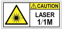
Class I(CDRH) and Class 1M (IEC) laser products. Statement 1055


Warning

Invisible laser radiation may be emitted from the end of the unterminated fiber cable or connector. Do not view directly with optical instruments. Viewing the laser output with certain optical instruments (for example, eye loupes, magnifiers, and microscopes) within a distance of 100 mm may pose an eye hazard. Statement 1056


Fans, Ventilation, and Airflow

The chassis temperature is regulated with internal fans. An onboard temperature sensor controls the fan speed. The fans are always on when the device is powered on. Under all conditions, the fans operate at the slowest speed possible to conserve power and reduce noise. When necessary, the fans operate at higher speeds under conditions of higher ambient temperature.