Security Overview

Security is a critical element of today's networking infrastructure. Network administrators and security officers are hard pressed to defend their network against attacks and breaches. As a result of hybrid clouds and remote employee connectivity, the security perimeter around networks is disappearing. There are multiple problems with the traditional ways of securing networks, including:

  • Very little emphasis is placed on ensuring the authenticity of the devices involved in the communication.

  • Securing the links between a pair of devices involves tedious and manual setup of keys and shared passwords.

  • Scalability and high availability solutions are often at odds with each other.

This chapter contains the following topics:

Cisco Catalyst SD-WAN Security Components

The Cisco Catalyst SD-WAN solution takes a fundamentally different approach to security, basing its core design around the following precepts:

  • Authentication—The solution ensures that only authentic devices are allowed to send traffic to one another.

  • Encryption—All communication between each pair of devices is automatically secure, completely eliminating the overhead involved in securing the links.

  • Integrity—No group keys or key server issues are involved in securing the infrastructure.

These three components—authentication, encryption, and integrity—are key to securing the Cisco Catalyst SD-WAN overlay network infrastructure.

The topics on Control Plane Security Overview and Data Plane Security Overview examine how authentication, encryption, and integrity are implemented throughout the Cisco Catalyst SD-WAN overlay network. The security discussion refers to the following illustration of the components of the Cisco Catalyst SD-WAN network—the Cisco SD-WAN Controller, the Cisco SD-WAN Validator, and the routers. The connections between these devices form the control plane (in orange) and the data plane (in purple), and it is these connections that need to be protected by appropriate measures to ensure the security of the network devices and all network traffic.

Security for Connections to External Devices

Cisco Catalyst SD-WAN routers can use the standards-based Internet Key Exchange (IKE) protocol when establishing IPsec tunnels between a device within the overlay network and a device that is external to the overlay network, such as a cloud-hosted service or a remote device. The Cisco Catalyst SD-WAN software supports IKE version 2, which performs mutual authentication and establishes and maintains security associations (SAs). IPsec provides confidentiality, data integrity, access control, and data source authentication for the traffic being exchanged over the IPsec tunnel.

Control Plane Security Overview

The control plane of any network determines the network topology and defines how to direct packets. In a traditional network, the control plane operations of building and maintaining routing and forwarding tables and directing packets towards their destination are handled by routing and switching protocols, which typically offer few or no mechanisms for authenticating devices or for encrypting routing updates and other control information. In addition, the traditional methods of providing security are manual and do not scale. For example, certificates are typically installed manually rather than in an automated fashion, and using preshared keys is not a secure approach for providing device security.

The Cisco Catalyst SD-WAN control plane has been designed with network and device security in mind. The foundation of the control plane is one of two security protocols derived from Secure Sockets Layer (SSL)—​the Datagram Transport Layer Security (DTLS) protocol and the Transport Layer Security (TLS) protocol. The Cisco SD-WAN Controller, which is the centralized brain of the Cisco Catalyst SD-WAN solution, establishes and maintains DTLS or TLS connections to all Cisco Catalyst SD-WAN devices in the overlay network—to the routers, the Cisco SD-WAN Validator, to Cisco SD-WAN Manager, and to other Cisco SD-WAN Controllers. These connections carry control plane traffic. DTLS or TLS provides communication privacy between Cisco Catalyst SD-WAN devices in the network, using the Advanced Encryption Standard (AES-256) encryption algorithm to encrypt all the control traffic sent over the connections. For information about how Cisco SD-WAN Manager communicates with devices and controllers, see Cisco Catalyst SD-WAN Manager in the Cisco Catalyst SD-WAN Getting Started Guide.

The privacy and encryption in the control plane, which is offered by DTLS and TLS, provide a safe and secure foundation for the other two security components, that is, authentication and integrity. To perform authentication, the Cisco Catalyst SD-WAN devices exchange digital certificates. These certificates, which are either installed by the software or hard-coded into the hardware, depending on the device, identify the device and allow the devices themselves to automatically determine which ones belong in the network and which are imposters. For integrity, the DTLS or TLS connections run AES-256-GCM, an authenticated encryption with associated data (AEAD) that provides encryption and integrity, which ensures that all the control and data traffic sent over the connections has not been tampered with.

Figure 1. Cisco Catalyst SD-WAN Control Plane Overview
The following are the control plane security components, which function in the privacy provided by DTLS or TLS connections:
  • AES-256-GCM: This algorithm provides encryption services.

  • Digital certificates: These are used for authentication.

  • AES-256-GCM: This is responsible for ensuring integrity.

DTLS and TLS Infrastructure

Security protocols derived from SSL provide the foundation for the Cisco Catalyst SD-WAN control plane infrastructure.

The first is the DTLS protocol, which is a transport privacy protocol for connectionless datagram protocols such as UDP, provides the foundation for the Cisco Catalyst SD-WAN control plane infrastructure. It is based on the stream-oriented Transport Layer Security (TLS) protocol, which provides security for TCP-based traffic. (TLS itself evolved from SSL.) The Cisco Catalyst SD-WAN infrastructure design uses DTLS running over UDP to avoid some of the issues with TCP, including the delays associated with stream protocols and some security issues. However, because UDP performs no handshaking and sends no acknowledgments, DTLS has to handle possible packet re-ordering, loss of datagrams, and data larger than the datagram packet size.

The control plane infrastructure can also be configured to run over TLS. This might be desirable in situations where the protections of TCP outweigh its issues. For example, firewalls generally offer better protection for TCP servers than for UDP servers.

The Cisco Catalyst SD-WAN software implements the standard version of DTLS with UDP, which is defined in RFC 6347. DTLS for use with other protocols is defined in a number of other RFCs. For TLS, the Cisco Catalyst SD-WAN software implements the standard version defined in RFC 5246. As described in the RFCs, Cisco Catalyst SD-WAN uses DTLS and TLS versions 1.2.

In the Cisco Catalyst SD-WAN architecture, the Cisco Catalyst SD-WAN devices use DTLS or TLS as a tunneling protocol, which is an application-level (Layer 4) tunneling protocol. When the Cisco SD-WAN Controller, Cisco SD-WAN Validator, Cisco SD-WAN Managers, and routers join the network, they create provisional DTLS or TLS tunnels between them as part of the device authentication process. After the authentication process completes successfully, the provisional tunnels between the routers and Cisco SD-WAN Controller, and those between the Cisco SD-WAN Validator and Cisco SD-WAN Controller, become permanent and remain up as long as the devices are active in the network. It is these authenticated, secure DTLS or TLS tunnels that are used by all the protocol applications running on the Cisco Catalyst SD-WAN devices to transport their traffic. For example, an OMP session on a router communicates with an OMP session on a Cisco SD-WAN Controller by sending plain IP traffic through the secure DTLS or TLS tunnel between the two devices. The Overlay Management Protocol is the Cisco Catalyst SD-WAN control protocol used to exchange routing, policy, and management information among Cisco Catalyst SD-WAN devices, as described in Overlay Routing Overview.
A Cisco Catalyst SD-WAN daemon running on each Cisco SD-WAN Controller and router creates and maintains the secure DTLS or TLS connections between the devices. This daemon is called vdaemon and is discussed later in this article. After the control plane DTLS or TLS connections are established between these devices, multiple protocols can create sessions to run and route their traffic over these connections—including OMP, Simple Network Management Protocol (SNMP), and Network Configuration Protocol (Netconf)—without needing to be concerned with any security-related issues. The session-related traffic is simply directed over the secure connection between the routers and Cisco SD-WAN Controller.

Control Plane Authentication

The Cisco Catalyst SD-WAN control plane uses digital certificates with 2048-bit RSA keys to authenticate the Cisco IOS XE Catalyst SD-WAN devices in the network. The digital certificates are created, managed, and exchanged by standard components of the public key infrastructure (PKI):

  • Public keys— These keys are generally known.

  • Private keys— These keys are private. They reside on each Cisco IOS XE Catalyst SD-WAN device and cannot be retrieved from the Cisco IOS XE Catalyst SD-WAN device.

  • Certificates signed by a root certification authority (CA)— The trust chain associated with the root CA needs to be present on all Cisco IOS XE Catalyst SD-WAN devices.

In addition to standard PKI components, the Cisco SD-WAN Controller serial numbers and the router chassis numbers are used in the authentication processes.

Let's first look at the PKI components that are involved in router authentication. On the Cisco IOS XE Catalyst SD-WAN device, the public and private keys and the certificates are managed automatically, by a hardware security chip that is built into the router called the Trust Anchor module (TAm). The TAm is a proprietary, tamper-resistant chip that features non-volatile secure storage for the Secure Unique Device Identifier (SUDI), as well as secure generation and storage of key pairs with cryptographic services including random number generation (RNG). When the routers are manufactured, this chip is programmed with a signed certificate. This certificate includes the router's public key, its serial number, and the router's private key. When the routers boot up and join the network, they exchange their certificates (including the router's public key and serial number) with other Cisco Catalyst SD-WAN routers as part of the router authentication process. Note that the router's private key always remains embedded in the router's Trusted Board ID chip, and it is never distributed, nor can it ever be retrieved from the router. In fact, any brute-force attempt to read the private key causes the hardware security chip to fail, thereby disabling all access to the router.

For Cisco SD-WAN Controllers, Cisco Catalyst SD-WAN Validators, and Cisco SD-WAN Manager systems, the public and private keys and the certificates are managed manually. When you boot these routers for the first time, the Cisco SD-WAN Controller software generates a unique private key–public key pair for each software image. The public key needs to be signed by the CA root. The network administrator then requests a signed certificate and manually installs it and the certificate chains on the Cisco SD-WAN Controllers, Cisco Catalyst SD-WAN Validators, and Cisco SD-WAN Manager systems. A typical network might have only a small handful of Cisco SD-WAN Controllers, Cisco Catalyst SD-WAN Validators, and Cisco SD-WAN Managers, so the burden of manually managing the keys and certificates on these routers is small.

When you place an order with Cisco using your Smart and Virtual Account, Cisco updates the Cisco Plug and Play (PNP) Portal with the chassis and certificate serial numbers of the devices that you purchased. You can then use Cisco SD-WAN Manager to sync the device information from the PNP portal using your Smart Account credentials. Alternatively. you can also download the trusted WAN Edge serial file from the PNP portal and upload it manually to Cisco SD-WAN Manager. Cisco SD-WAN Manager then broadcasts this information to the other controllers. Both the authorized serial number file and the file listing the Cisco SD-WAN Controller serial numbers are uploaded and installed on Cisco Catalyst SD-WAN Validators. Then, during the automatic authentication process, as pairs of devices (routers and controllers) are establishing DTLS control connections, each device compares the serial numbers (and for routers, the chassis numbers) to those in the files installed on the router. A router allows a connection to be established only if the serial number or serial–chassis number combination (for a router) matches. Note that routers only make control connections to the controllers and not to other routers.

You can display the installed Cisco SD-WAN Controller authorized serial numbers using the show control valid-vsmarts command on a Cisco SD-WAN Controller and the show orchestrator valid-vsmarts command on a Cisco Catalyst SD-WAN Validator. You can also run show sdwan control valid-vsmarts on Cisco IOS XE Catalyst SD-WAN devices. You can display the installed router authorized serial and chassis number associations using the show control valid-vedges command on a Cisco SD-WAN Controller and the show orchestrator valid-devices command on a Cisco Catalyst SD-WAN Validator.

Now, let's look at how the PKI authentication components and the router serial and chassis numbers are used to authenticate router on the Cisco SD-WAN Controller overlay network. When Cisco SD-WAN Controllers, Cisco Catalyst SD-WAN Validators, and routers first boot up, they establish secure DTLS or TLS connections between the Cisco SD-WAN Controllers and the routers. Over these connections, the devices authenticate each other, using the public and private keys, the signed certificates, and the routers serial numbers and performing a series of handshake operations to ensure that all the devices on the network are valid and not imposters. The following figure illustrates the key and certificate exchange that occurs when the Cisco SD-WAN Controller devices boot. For details about the authentication that occurs during the bringup process, see Bringup Sequence of Events.

Control Plane Encryption

Control plane encryption is done by either DTLS, which is based on the TLS protocol, or TLS. These protocol encrypt the control plane traffic that is sent across the connections between Cisco Catalyst SD-WAN devices to validate the integrity of the data. TLS uses asymmetric cryptography for authenticating key exchange, symmetric encryption for confidentiality, and message authentication codes for message integrity.

A single Cisco Catalyst SD-WAN device can have DTLS or TLS connections to multiple Cisco Catalyst SD-WAN devices, so vdaemon creates a kernel route for each destination. For example, a router would typically have one kernel route, and hence one DTLS or TLS connection, for each Cisco SD-WAN Controller. Similarly, a Cisco SD-WAN Controller would have one kernel route and one DTLS or TLS connection for each router in its domain.

Control Plane Integrity

The Cisco Catalyst SD-WAN design implements control plane integrity by combining two security elements: AES-GCM message digests, and public and private keys.

AES-GCM authenticated encryption provides high performance encryption that generates message digests (sometimes called simply digests) for each packet sent over a control plane connection. The receiver then generates a digest for the packet, and if the two match, the packet is accepted as valid. This encryption allows verification that the packet's contents have not been tampered with.

The second component of control plane integrity is the use of public and private keys. When a control plane connection is being established, a local Cisco Catalyst SD-WAN device sends a challenge to a remote device. The remote device encrypts the challenge by signing it with its private key, and returns the signed challenge to the local device. The local device then uses the remote device's public key to verify that the received challenge matches the sent challenge.

Then, once a control plane connection is up, keys are used to ensure that packets have been sent by a trusted host and were not inserted midstream by an untrusted source. The authenticity of each packet is verified through encryption and decryption with symmetric keys that were exchanged during the process of establishing the control connection.

Data Plane Security Overview

The data plane of any network is responsible for handling data packets that are transported across the network. The data plane is also sometimes called the forwarding plane. In a traditional network, data packets are typically sent directly over the Internet or another type of public IP cloud, or they could be sent through MPLS tunnels. If the routers in the Cisco Catalyst SD-WAN overlay network were to send traffic over a public IP cloud, the transmission would be insecure. Anyone can sniff the traffic, and implement various types of attacks, including man-in-the-middle (MITM) attacks.

The underlying foundation for security in the Cisco Catalyst SD-WAN data plane is the security of the control plane. Because the control plane is secure—all the devices are validated, and control traffic is encrypted and cannot be tampered with—you can be confident about using routes and other information learned from the control plane, to create and maintain secure data paths throughout a network of routers.

The data plane provides the infrastructure for sending data traffic among the routers in the Cisco Catalyst SD-WAN overlay network. Data plane traffic travels within secure Internet Security (IPsec) connections. The Cisco Catalyst SD-WAN data plane implements the key security components of authentication, encryption, and integrity, as shown in the figure, and described below.

Figure 2. Cisco Catalyst SD-WAN Data Plane Overview
  • Authentication: As mentioned, the Cisco Catalyst SD-WAN control plane contributes the underlying infrastructure for data plane security. In addition, authentication is enforced by two other mechanisms:

    • In the traditional key exchange model, the Cisco Catalyst SD-WAN Controller sends IPsec encryption keys to each edge device.

      In the pairwise keys model, the Cisco SD-WAN Controller sends Diffie-Hellman public values to the edge devices, and they generate pairwise IPsec encryption keys using Elliptic-curve Diffie-Hellman (ECDH) and a P-384 curve. For more information, see Pairwise Keys.

    • By default, IPsec tunnel connections use an enhanced version of the Encapsulating Security Payload (ESP) protocol for authentication on IPsec tunnels.

  • Encryption: An enhanced version of ESP protects a data packet's payload. This version of the protocol also checks the outer IP and UDP headers. Hence, this option supports an integrity check of the packet, which is similar to the Authentication Header (AH) protocol. Data encryption is done using the AES-GCM-256 cipher.

  • Integrity: To guarantee that data traffic is transmitted across the network without being tampered with, the data plane implements several mechanisms from the IPsec security protocol suite:

    • An enhanced version of the ESP protocol encapsulates the payload of data packets.

    • The enhanced version of ESP uses an AH-like mechanism to check the integrity of the outer IP and UDP headers. You can configure the integrity methods supported on each router, and this information is exchanged in the router's TLOC properties. If two peers advertise different authentication types, they negotiate the type to use, choosing the strongest method.

    • The anti-replay scheme protects against attacks in which an attacker duplicates encrypted packets.

Data Plane Authentication and Encryption

During the bringup of the overlay, the Cisco Catalyst SD-WAN Controller establishes the information for edge routers to send data to each other. However before a pair of routers can exchange data 
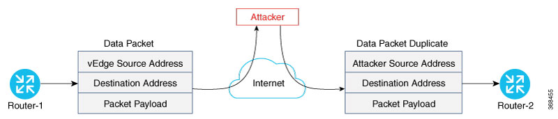
traffic, they establish an IPsec connection between them, which they use as a secure communications channel. Since the Cisco Catalyst SD-WAN Controller has authenticated the devices, the devices do not further authenticate each other.

Control plane communications have allowed the edge device to have enough information to establish IPsec tunnels. Edge devices simply send data through the tunnels. There is no additional authentication step.

In a traditional IPsec environment, key exchange is handled by the Internet Key Exchange (IKE) protocol. IKE first sets up secure communications channels between devices and then establishes security associations (SAs) between each pair of devices that want to exchange data. IKE uses a Diffie-Hellman key exchange algorithm to generate a shared key that encrypts further IKE communication. To establish SAs, each device (n) exchanges keys with every other device in the network and creates per-pair keys, generating a unique key for each remote device. This scheme means that in a fully meshed network, each device has to manage n2 key exchanges and (n-1) keys. As an example, in a 1,000-node network, 1,000,000 key exchanges are required to authenticate the devices, and each node is responsible for maintaining and managing 999 keys.

The discussion in the previous paragraph points out why an IKE-style key exchange does not scale as network size increases and why IKE could be a bottleneck in starting and in maintaining data exchange on a large network:

  • The handshaking required to set up the communications channels is both time consuming and resource intensive.

  • The processing required for the key exchange, especially in larger networks, can strain network resources and can take a long time.

The Cisco Catalyst SD-WAN implementation of data plane authentication and encryption establishes SAs between each pair of devices that want to exchange data, but it dispenses with IKE altogether. Instead, to provide a scalable solution to data plane key exchange, the Cisco Catalyst SD-WAN solution takes advantage of the fact that the DTLS control plane connections in the Cisco Catalyst SD-WAN overlay network are known to be secure. Because the Cisco Catalyst SD-WAN control plane establishes authenticated, encrypted, and tamperproof connections, there is no need in the data plane to set up secure communications channels to perform data plane authentication.

In the Cisco Catalyst SD-WAN network for unicast traffic, data plane encryption is done by AES-256-GCM, a symmetric-key algorithm that uses the same key to encrypt outgoing packets and to decrypt incoming packets. Each router periodically generates an AES key for its data path (specifically, one key per TLOC) and transmits this key to the Cisco SD-WAN Controller in OMP route packets, which are similar to IP route updates. These packets contain information that the Cisco SD-WAN Controller uses to determine the network topology, including the router's TLOC (a tuple of the system IP address and traffic color) and AES key. The Cisco SD-WAN Controller then places these OMP route packets into reachability advertisements that it sends to the other routers in the network. In this way, the AES keys for all the routers are distributed across the network. Even though the key exchange is symmetric, the routers use it in an asymmetric fashion. The result is a simple and scalable key exchange process that uses the Cisco Catalyst SD-WAN Controller.

In Cisco SD-WAN Release 19.2.x and Cisco IOS XE SD-WAN Release 16.12.x onwards, Cisco Catalyst SD-WAN supports IPSec pairwise keys that provide additional security. When IPSec pairwise keys are used, the edge router generates public and private Diffie-Hellman components and sends the public value to the Cisco SD-WAN Controller for distribution to all other edge devices. For more information, see IPsec Pairwise Keys

If control policies configured on a Cisco SD-WAN Controller limit the communications channels between network devices, the reachability advertisements sent by the Cisco SD-WAN Controller contain information only for the routers that they are allowed to exchange data with. So, a router learns the keys only for those routers that they are allowed to communicate with.

To further strengthen data plane authentication and encryption, routers regenerate their AES keys aggressively (by default, every 24 hours). Also, the key regeneration mechanism ensures that no data traffic is dropped when keys change.

In the Cisco Catalyst SD-WAN overlay network, the liveness of SAs between router peers is tracked by monitoring BFD packets, which are periodically exchanged over the IPsec connection between the peers. IPsec relays the connection status to the Cisco SD-WAN Controllers. If data connectivity between two peers is lost, the exchange of BFD packets stops, and from this, the Cisco SD-WAN Controller learns that the connection has been lost.

The IPsec software has no explicit SA idle timeout, which specifies the time to wait before deleting SAs associated with inactive peers. Instead, an SA remains active as long as the IPsec connection between two routers is up, as determined by the periodic exchange of BFD packets between them. Also, the frequency with which SA keys are regenerated obviates the need to implement an implicit SA idle timeout.

In summary, the Cisco Catalyst SD-WAN data plane authentication offers the following improvements over IKE:

  • Because only n +1 keypaths are required rather than the n2 required by IKE, the Cisco Catalyst SD-WAN solution scales better as the network grows large.

  • Keys are generated and refreshed locally, and key exchange is performed over a secure control plane.

Data Plane Integrity

The following components contribute to the integrity of data packets in the Cisco Catalyst SD-WAN data plane:

  • UDP – Encapsulate ESP within UDP packets per RFC 3948, UDP Encapsulation of IPsec ESP packets.

  • ESP, which is a standard IPsec encryption protocol, protects (via encryption and authentication) the inner header, data packet payload, and ESP trailer in all data packets. SDWAN complies with RFC 4303, IP Encapsulating Security Payload (ESP).

  • Enhancements to ESP, which protect (via authentication) the outer IP and UDP headers. This mimics the functionality of the AH protocol.

  • Anti-replay, which is also part of the standard IPsec software suite, provides a mechanism to number all data packets and to ensure that receiving routers accept only packets with unique numbers.

The first of these components, ESP, is the standard IPsec encryption protocol. ESP protects a data packet’s payload and its inner IP header fields both by encryption, which occurs automatically, and authentication. For authentication, ESP performs a hash calculation on the data packet's payload and inner header fields using AES-GCM and places the resultant hash (also called a digest) into a field at the end of the packet. (A hash is a one-way compression.) The receiving device performs the same checksum and compares its calculated hash with that in the packet. If the two checksums match, the packet is accepted. Otherwise, it is dropped. In the figure below, the left stack illustrates the ESP/UDP encapsulation. ESP encrypts and authenticates the inner headers, payload, MPLS label (if present), and ESP trailer fields, placing the hash in the ICV checksum field at the end of the packet. The outer header fields added by ESP/UDP are neither encrypted nor authenticated.

In the Cisco Catalyst SD-WAN solution, there are also enhancements to ESP to enhance its behavior to cover more of the datagram. These enhancements are similar to the way that AH works. This enhancement performs a checksum that includes calculating the checksum over all the fields in the packet—the payload, the inner header, and also all the non-mutable fields in the outer IP header. AH places the resultant hash into the last field of the packet. The receiving device performs the same checksum, and accepts packets whose checksums match. In the figure below, the center stack illustrates the encapsulation performed by the enhanced version of ESP. ESP again encrypts the inner headers, payload, MPLS label (if present), and ESP trailer fields, and now mimics AH by authenticating the entire packet—the outer IP and UDP headers, the ESP header, the MPLS label (if present), the original packet, and the ESP trailer—and places its calculated hash into the ICV checksum field at the end of the packet.

For situations in which data packet authentication is not required, you can disable data packet authentication altogether. In this case, data packets are processed just by ESP, which encrypts the original packet, the MPLS label (if present), and the ESP trailer. This scheme is illustrated in the right stack in the figure below.

Note that Cisco Catalyst SD-WAN devices exchange not only the encryption key (which is symmetric), but also the authentication key that is used to generate the digest. Both are distributed as part of the TLOC properties for a router.

Even though the IPsec connections over which data traffic is exchanged are secure, they often travel across a public network space, such as the Internet, where it is possible for a hacker to launch a replay attack (also called a man-in-the-middle, or MITM, attack) against the IPsec connection. In this type of attack, an adversary tampers with the data traffic by inserting a copy of a message that was previously sent by the source. If the destination cannot distinguish the replayed message from a valid message, it may authenticate the adversary as the source or may incorrectly grant to the adversary unauthorized access to resources or services.

As a counter to such attacks, the Cisco Catalyst SD-WAN overlay network software implements the IPsec anti-replay protocol. This protocol consists of two components, both of which protect the integrity of a data traffic stream. The first component is to associate sequence numbers with each data packets. The sender inserts a sequence number into each IPsec packet, and the destination checks the sequence number, accepting only packets with unique, non-duplicate sequence numbers. The second component is a sliding window, which defines a range of sequence numbers that are current. The sliding window has a fixed length. The destination accepts only packets whose sequence numbers fall within the current range of values in the sliding window, and it drops all others. A sliding window is used rather than accepting only packets whose sequence number is larger than the last known sequence number, because packets often do not arrive in order.

When the destination receives a packet whose sequence number is larger than the highest number in the sliding window, it slides the window to the right, thus changing the range of valid sequences numbers it will accept. This scheme protects against an MITM type of attack because, by choosing the proper window size, you can ensure that if a duplicate packet is inserted into the traffic stream, its sequence number will either be within the current range but will be a duplicate, or it will be smaller than the lowest current value of the sliding window. Either way, the destination will drop the duplicate packet. So, the sequence numbering combined with a sliding window provide protection against MITM type of attacks and ensure the integrity of the data stream flowing within the IPsec connection.

Carrying VPN Information in Data Packets

For enterprise-wide VPNs, Cisco Catalyst SD-WAN devices support MPLS extensions to data packets that are transported within IPsec connections. The figure to the right shows the location of the MPLS information in the data packet header. These extensions provide the security for the network segmentation (that is, for the VPNs) that is needed to support multi-tenancy in a branch or segmentation in a campus. The Cisco Catalyst SD-WAN implementation uses IPsec UDP-based overlay network layer protocol encapsulation as defined in RFC 4023. The security is provided by including the Initialization Vector (IV) at the beginning of the payload data in the ESP header.

Unified Threat Defense for Cisco Catalyst SD-WAN

The attack surface at branch locations continues to increase with local breakouts, especially with direct internet access. As a result, protecting the branch with right security capabilities is even more critical than before. Secure SD-WAN brings key security capabilities embedded natively in SD-WAN solution with cloud-based single-pane of management for both SD-WAN and security capabilities.

The security capabilities include enterprise firewall with application awareness, intrusion prevention systems with Cisco Talos signatures, URL-Filtering, and DNS/Web-layer Security. The security capabilities help customers achieve PCI compliance, segmentation, threat protection, content filtering and much more. With Cisco Umbrella DNS/Web-security layer, you get a layer of protection for all branch users from malware, botnets, phishing, and targeted online attacks.

Cisco Catalyst SD-WAN offers the following security features:

Table 1. Cisco Catalyst SD-WAN SD-WAN Security Features

Feature

Description

Enterprise Firewall with Application Awareness

A stateful firewall with NBAR2 application detection engine to provide application visibility and granular control, capable of detecting 1400+ applications.

Intrusion Prevention System

This system is backed by Cisco Talos signatures and are updated automatically. The Intrusion Prevention System is deployed using a security virtual image.

URL Filtering

Enforces acceptable use controls to block or allow URLs based on 82 different categories and a web reputation score. The URL Filtering system is deployed using a security virtual image.

Advanced Malware Protection

Global threat intelligence, advanced sandboxing, and real-time malware blocking to prevent breaches. It also continuously analyzes file activity across your extended network, so you can quickly detect, contain, and remove advanced malware. The Advanced Malware Protection system is deployed using a security virtual image.

Cisco Umbrella Integration

Cloud-delivered enterprise network security which provides users with a first line of defense against cyber security threats.

Supported Platforms

For UTD features that use the Security Virtual Image (Intrusion Prevention System, URL filtering, and Advanced Malware Protection), only the following platforms are supported:

  • Cisco 4351 Integrated Services Router (ISR 4351)

  • Cisco 4331 Integrated Services Router (ISR 4331)

  • Cisco 4321 Integrated Services Router (ISR 4321)

  • Cisco 4221X Integrated Services Router (ISR 4221X)

  • Cisco 4431 Integrated Services Router (ISR 4431)

  • Cisco 4451 Integrated Services Router (ISR 4451)

  • Cisco 4461 Integrated Services Router (ISR 4461)

  • Cisco Integrated Services Router 1111X-8P (C1111X-8P)

  • Cisco Integrated Services Router 1121X-8PLTEP (C1121X-8PLTEP)

  • Cisco Integrated Services Router 1121X-8PLTEPWY (C1121X-8PLTEPWY)

  • Cisco Integrated Services Router 1126X-8PLTEP (C1126X-8PLTEP)

  • Cisco Integrated Services Router 1127X-8PLTEP (C1127X-8PLTEP)

  • Cisco Integrated Services Router 1127X-8PMLTEP (C1127X-8PMLTEP)

  • Cisco Integrated Services Router 1161X-8P (C1161X-8P)

  • Cisco Integrated Services Router 1161X-8PLTEP (C1161X-8PLTEP)

  • Cisco Catalyst 8200 Series Edge Platforms

  • Cisco Catalyst 8300 Series Edge Platforms

  • Cisco Cloud Services Router 1000v series (CSR 1000v) on Amazon Web Services (AWS)

  • Cisco Integrated Services Virtual Router

  • Cisco Catalyst 8000V Edge Software

Restrictions

  • ISR 1111X-8P does not support all of the IPS signatures because it does not support the pre-compiled rules of Snort.

  • For Intrusion Prevention, URL-Filtering, and Advanced Malware Prevention (features that leverage the Security Virtual Image), the following restrictions apply:

    • ISR platforms must meet the following minimum requirements:

      • 8 GB flash memory

      • 8 GB DRAM

    • When you create a policy for these features, you must specify a target service VPN. When you enable these features on a single VPN, the corresponding policy is applied to both traffic from and to the VPN. Note that this is when you specify one VPN and not a comma-separated list of VPNs.

      For example, if you applied the policy to a single VPN, say VPN 3, then the security policy is applied in both the following cases:

      • Traffic from VPN 3 to VPN 2.

      • Traffic from VPN 6 to VPN 3.

    • By default, when a policy is applied to VPN 0 (the global VPN) and enterprise tunnels are in VPN 0, all VPN traffic that uses the enterprise tunnels are not inspected. If you want the traffic of other VPNs to be inspected, you must explicitly specify the VPNs in the policy.

      For example, in both the following cases, a VPN 0 security policy does not inspect traffic:

      • Traffic originating from a service-side VPN (for example VPN 3) that is transmitted through the enterprise tunnel. This traffic is not inspected because VPN 3 is not explicitly specified in the policy.

      • Traffic from the enterprise tunnel that is sent to the service-side VPN (for example VPN 3). This traffic is also not inspected because VPN 3 is not explicitly specified in the policy.

    • You can enable these features on service and transport VPNs. This includes VPN 0.

    • The VirtualPortGroup interface for data traffic for UTD uses the 192.0.2.0/30 IP address range. The use of the 192.0.2.0/24 subnet is defined in RFC 3330. Cisco SD-WAN Manager also automatically uses 192.0.2.1 and 192.0.2.2 for the data virtual private gateway in VPN 0 for UTD. You can modify this using a CLI template on Cisco SD-WAN Manager to configure the device. Due to this, you should not use these IP addresses on devices. Alternatively, you can change the routing configuration on the device to use a different IP address from the 192.0.2.0/24 subnet.

  • Cisco Catalyst 8200 Series Edge Platforms and Cisco Catalyst 8300 Series Edge Platforms must meet the following minimum requirements to support UTD:

    • 8 GB DRAM

    • 16 GB M.2 USB storage

Security Provided by NAT Devices

While the primary purpose of NAT devices is to allow devices with private IP addresses in a local-area network (LAN) to communicate with devices in public address spaces, such as the Internet, NAT devices also inherently provide a level of security, functioning as hardware firewalls to prevent unwanted data traffic from passing through the routers and to the LAN networks in the service-side networks connected to the router.

To enhance the security at branch sites, you can place the router behind a NAT device. The router can interact with NAT devices configured with the following Session Traversal Utilities for NAT (STUN) methods, as defined in RFC 5389 :

  • Full-cone NAT, or one-to-one NAT—This method maps an internal address and port pair to an external address and port. Any external host can send packets to LAN devices behind the router by addressing them to the external address and port.

  • Address-restricted cone NAT, or restricted-cone NAT—This method also maps an internal address and port to and external address and port. However, an external host can send packets to the internal device only if the external address (and any port at that address) has received a packet from the internal address and port.

  • Port-restricted cone NAT—This method is a stricter version of restricted-cone NAT, in which an external host can send packets to the internal address and port only if the external address and port pair has received a packet from that internal address and port. The external device must send packets from the specific port to the specific internal port.

  • Symmetric NAT—With this method, each request from the same internal IP address and port to an external IP address and port is mapped to a unique external source IP address and port. If the same internal host sends a packet with the same source address and port but to a different destination, the NAT device creates a different mapping. Only an external host that receives a packet from an internal host can send a packet back. The routers support symmetric NAT only on one side of the WAN tunnel. That is, only one of the NAT devices at either end of the tunnel can use symmetric NAT. When a router operates behind a NAT device running symmetric NAT, only one of the NAT devices at either end of the tunnel can use symmetric NAT. The router that is behind a symmetric NAT cannot establish a BFD tunnel with a remote router that is behind a symmetric NAT, an address-restricted NAT, or a port-restricted NAT.  To allow a router to function behind a symmetric NAT, you must configure the Cisco SD-WAN Manager and Cisco SD-WAN Controller control connections to use TLS. DTLS control connections do not work through a symmetric NAT.