Cisco 1-Port Channelized OC-12 Line Card Installation and Configuration Guide
Bias-Free Language
The documentation set for this product strives to use bias-free language. For the purposes of this documentation set, bias-free is defined as language that does not imply discrimination based on age, disability, gender, racial identity, ethnic identity, sexual orientation, socioeconomic status, and intersectionality. Exceptions may be present in the documentation due to language that is hardcoded in the user interfaces of the product software, language used based on RFP documentation, or language that is used by a referenced third-party product. Learn more about how Cisco is using Inclusive Language.
- Updated:
- March 20, 2009
Chapter: Overview of Channelized 1-Port OC12 Line Card
Overview: 1-Port Channelized OC-12 Line Card
1-Port Channelized OC-12 Line Card Overview
The 1-Port Channelized OC-12 Line Card is a single Optical Carrier-12 (OC-12) interface with DS-1 channelization capability, designed for Cisco XR 12000 Series Routers with Cisco IOS XR Software Release 3.8.0 installed. The 1-Port Channelized OC-12 Line Card has a serial interface that can be channelized to carry T1/DS1/DS0. The 1-Port Channelized OC-12 Line Card does not support Packet-over-SONET (POS) interfaces. The line card supports only SONET framing and does not support DS-3 for the Cisco XR 12000 Series Routers. Table 1-1 lists the SONET channelization modes that are supported on the 1-Port Channelized OC-12 Line Card. The Cisco product number for 1-Port Channelized OC-12 Line Card is CHOC12/DS1-IR-SC=.
|
|
|---|
CT3 Mode mapping: STS-12 <> STS-1 <> DS3 <> DS-1 <> nDS-0 |
VT1.5 Mode mapping: STS-12 <> STS-1 <> VTG <>VT-1.5 <> DS-1<> nDS-0 |
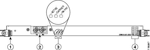
The line card interfaces with the Cisco XR 12000 Series Router switch fabric and provides a full-duplex short cable (SC), single-mode, short-reach optical interface. Figure 1-1 shows the front view of this line card.
Figure 1-1 1-Port Channelized OC-12 Line Card
|
|
Ejector lever (one at each end) |
|
Status LEDs |
|
|
Port 0 |
|
Alphanumeric LEDs |
Router Hardware Installation
For Cisco XR 12000 Series Router hardware installation and configuration information, refer to the installation and configuration guide for your router. The guide includes information on the router switch fabric and how it affects the operation of line cards, as well as line card slot locations, slot width, and other requirements.
Supported Platforms
The 1-Port Channelized OC-12 Line Cards are supported on all Cisco XR 12000 Series Routers.

Note ![]() To support the requirements of this line card, the Cisco XR 12000 Series Router must have at least one clock and scheduler card (CSC) installed. For additional information, refer to the installation and configuration guide for your Cisco XR 12000 Series Router.
To support the requirements of this line card, the Cisco XR 12000 Series Router must have at least one clock and scheduler card (CSC) installed. For additional information, refer to the installation and configuration guide for your Cisco XR 12000 Series Router.
Product Specifications
Table 1-2 provides specifications regarding the engine supported, the Cisco IOS XR software release, the chassis supported, and per-chassis port densities.
Physical and Electrical Specifications
Table 1-3 provides details about the physical and electrical specifications of the Cisco XR 12000 Series Router 1-Port Channelized OC-12 Line Card.
Optical Specifications
Table 1-4 provides details about the optical specifications of the Cisco XR 12000 Series Router 1-Port Channelized OC-12 Line Card.
Ordering Information
To place an order, contact your local Cisco Systems representative or visit the ordering page on the Cisco website. Use the ordering information in Table 1-5.
|
|
|
|---|---|
CHOC12/DS1-IR-SC |
Cisco XR 12000 Series Router 1-Port Channelized OC-12/STM-4 Line Card |
1-Port Channelized OC-12 Line Card Hardware and Software Compatibility
For successful installation and configuration of the 1-Port Channelized OC-12 Line Card, ensure that the compatible hardware and the Cisco IOS XR Software Release are installed. This section provides details regarding the compatible Cisco IOS XR Software Release and the hardware revision requirements.
Cisco IOS XR Software Release Requirements
Table 1-6 lists the Cisco IOS XR software release that is compatible with the 1-Port Channelized OC-12 Line Card.
Hardware Revision Requirements
To ensure compatibility with Cisco IOS XR software, the 1-Port Channelized OC-12 Line Card must have a hardware revision number 7 or above. The number is printed on a label affixed to the component side of the card. The hardware revision number can be displayed by using the show diag 0/1/cpu0 command.
Table 1-7 lists the hardware revision number for the 1-Port Channelized OC-12 Line Card.
1-Port Channelized OC-12 Line Card LEDs
See Figure 1-1 for the location of the LEDs on the 1-Port Channelized OC-12 Line Card. The different operating states of the status LEDs are shown in Table 1-8.
Alphanumeric LEDs
The 1-Port Channelized OC-12 Line Cards have two four-digit alphanumeric LED displays at one end of the faceplate (near the ejector lever) that display a sequence of messages indicating the state of the card. In general, the LEDs do not come on until the route processor (RP) recognizes and powers up the card. As it boots, the line card displays a sequence of messages similar to those in Table 1-9.
Note ![]() Some messages might appear in brief and for a short time. Also, some messages listed in Table 1-9 may not appear on your line card.
Some messages might appear in brief and for a short time. Also, some messages listed in Table 1-9 may not appear on your line card.
|
|
|
|
|---|---|---|
IOX RUN |
Line card is enabled and ready for use. |
Line Card (LC) |
MBI RUN |
Minimal boot image (MBI) is running. |
Route Processor (RP) |
MANT MoDE |
Line card or router is running in a maintenance mode. |
RP |
DIAG LNCH |
Field diagnostic is being launched. |
RP |
DDNL FAIL |
Field diagnostic download has failed. |
RP |
DIAG RUN |
Field diagnostic utility is running. |
RP |
DIAG TOUT |
Field diagnostic is timed-out. |
RP |
DIAG PASS |
Field diagnostic run has passed. |
RP |
DIAG FAIL |
Field diagnostic run has failed. |
RP |
UNSU UNSU |
Line card type is not supported. |
RP |
LOW MEM |
Line card or router is running in low memory. |
RP |
NOTP |
Line card is not present. |
RP |
NOPW |
Line card is not powered on. |
RP |
PWRD |
Line card is powered on. |
RP |
BOOT |
Line card is booting. |
RP |
ADON |
Line card is administratively down. |
RP |
RSET |
Line card is in reset state. |
RP |
BRDN |
Line card is being brought down. |
RP |
PWRD |
Line card is present and is powered on. |
RP |
DGDL |
Field diagnostic is downloading. |
RP |
DGUN |
Field diagnostic is not running in a monitored state. |
RP |
1 The entire LED sequence shown in Table 1-9 might occur too quickly for you to read; therefore, this sequence is provided in tabular form as baseline information on how a line card should function at startup. |
1-Port Channelized OC-12 Line Card Interface Specifications
The physical layer interface for the channelized OC-12 line card is Optical Carrier-12 (OC-12, the specification for SONET STS-12c transmission rates). The channelized OC-12 line card is not designed to support Packet-over-SONET (POS) but supports serial interface, which results in the creation of a serial interface. By default, the controller comes up in 12xSTS-1 mode. It does not support clear channel. The 1-Port Channelized OC-12 Line Card is scalable to 168 multilink interfaces with a maximum of 12 member links in a bundle, 992 Frame relay PVCs per main interface, 2048 Frame Relay PVCs per line card, and 448 LMI sessions. Depending on the channel buffers available, maximum serial interfaces can range from 336 to 840. Depending on number of time slots configured, different numbers of channel buffers are consumed changing the maximum number of serial interfaces.
Each channelized OC-12 line card has one pair of short cable (SC) type fiber receptacles to allow connection to single-mode optical fiber. Packet data is transported using Point-to-Point Protocol (PPP), Frame Relay, or HDLC and is mapped into the STS-12c frame. (RFC 1619). The 1-Port Channelized OC-12 Line Card supports the following MIBs:
•![]() CISCO-ENTITY-ASSET-MIB
CISCO-ENTITY-ASSET-MIB
•![]() CISCO-ENTITY-FRU-CONTROL-MIB
CISCO-ENTITY-FRU-CONTROL-MIB
•![]() CISCO-SONET-MIB
CISCO-SONET-MIB
•![]() CISCO-ENTITY-SENSOR-MIB
CISCO-ENTITY-SENSOR-MIB
•![]() DS1-MIB
DS1-MIB
•![]() DS3-MIB
DS3-MIB
•![]() ENTITY-MIB
ENTITY-MIB
•![]() IF-MIB
IF-MIB
•![]() MIB-2
MIB-2
•![]() SONET-MIB
SONET-MIB
 Feedback