Cisco 1-Port Channelized OC-12 Line Card Installation and Configuration Guide
Bias-Free Language
The documentation set for this product strives to use bias-free language. For the purposes of this documentation set, bias-free is defined as language that does not imply discrimination based on age, disability, gender, racial identity, ethnic identity, sexual orientation, socioeconomic status, and intersectionality. Exceptions may be present in the documentation due to language that is hardcoded in the user interfaces of the product software, language used based on RFP documentation, or language that is used by a referenced third-party product. Learn more about how Cisco is using Inclusive Language.
- Updated:
- April 4, 2009
Chapter: Verifying and Troubleshooting the Line Card
Verifying and Troubleshooting the Line Card Installation
Overview
This chapter provides various methods by which you can troubleshoot the line card installation. The troubleshooting tips are helpful for identifying the problem and resolving it. The following sections describe how to verify and troubleshoot the line card installation:
•![]() Troubleshooting the Installation
Troubleshooting the Installation
Initial Boot Process

Note ![]() Many new line cards are designated as administratively down by default. Status LEDs are off until you configure the interfaces and use the no shutdown command.
Many new line cards are designated as administratively down by default. Status LEDs are off until you configure the interfaces and use the no shutdown command.
During a typical line card boot process, the following events occur:
1. ![]() The line card maintenance bus (Mbus) module receives power and begins executing the Mbus software.
The line card maintenance bus (Mbus) module receives power and begins executing the Mbus software.
2. ![]() The line card Mbus module determines the type of card on which it resides, performs internal checks, and prepares to accept the Cisco IOS XR software from the route processor (RP).
The line card Mbus module determines the type of card on which it resides, performs internal checks, and prepares to accept the Cisco IOS XR software from the route processor (RP).
3. ![]() The RP powers up the line card and loads the line card with the Cisco IOS XR software.
The RP powers up the line card and loads the line card with the Cisco IOS XR software.
To verify that the line card is working properly, perform the following operational checks:
•![]() During the line card boot process, observe the line card alphanumeric LEDs to ensure that the card is running the typical initialization sequence. The sequence should end with the alphanumeric status message `IOX RUN'.
During the line card boot process, observe the line card alphanumeric LEDs to ensure that the card is running the typical initialization sequence. The sequence should end with the alphanumeric status message `IOX RUN'.
•![]() Observe the line card status LEDs to verify that the Active LED (Link LED or status LED for line cards with no Active LED) is on. If an Active LED is not on, verify that the associated interface is not shut down.
Observe the line card status LEDs to verify that the Active LED (Link LED or status LED for line cards with no Active LED) is on. If an Active LED is not on, verify that the associated interface is not shut down.
If one of these conditions is not met, refer to the "Advanced Line Card Troubleshooting" section to identify any possible problems.
Status LEDs
After installing the line card and connecting the interface cables, verify that the line card is working properly by checking the following LEDs on the faceplate:
•![]() Interface status LEDs show the status of each fiber-optic connector. Channelized line cards with optical interfaces can contain some or all of the following status LEDs (see Figure 1-1):
Interface status LEDs show the status of each fiber-optic connector. Channelized line cards with optical interfaces can contain some or all of the following status LEDs (see Figure 1-1):
–![]() Active—Indicates the active condition of this port
Active—Indicates the active condition of this port
–![]() Carrier—Indicates the status of SONET framing reception on this port
Carrier—Indicates the status of SONET framing reception on this port
–![]() RX PKT—Indicates that data is being received on this port
RX PKT—Indicates that data is being received on this port
Line cards with T3 ports contain a single status LED:
•![]() Alphanumeric LEDs. Two four-digit alphanumeric LEDs display messages that explain the state of the line card. (See the "Alphanumeric LEDs" section on page 1-6.)
Alphanumeric LEDs. Two four-digit alphanumeric LEDs display messages that explain the state of the line card. (See the "Alphanumeric LEDs" section on page 1-6.)
The status LEDs might not be on until you have configured the line card interfaces (or turned them on, if they were shut down). To verify correct operation of each interface, complete the configuration procedures for the line card. (See the "Configuring and Troubleshooting Line Card Interfaces" section.)
Troubleshooting the Installation
Note ![]() Many new line cards are designated as administratively down by default. Status LEDs are off until you configure the interfaces and use the no shutdown command.
Many new line cards are designated as administratively down by default. Status LEDs are off until you configure the interfaces and use the no shutdown command.
If the Active LED (Link LED or status LED for line cards with no Active LED) or the alphanumeric display LEDs on a line card do not come on, there is either a problem with the line card installation or a hardware failure. To verify that the line card is installed correctly, follow these steps:
Step 1 ![]() If the Active LED fails to come on, but the alphanumeric display LEDs on the line card indicate activity, verify that the initialization sequence ends with IOX RUN. If this is the case, verify that the interface is not shut down. If it is not, suspect a circuitry problem with the Active LED and contact a Cisco Technical Support for further assistance.
If the Active LED fails to come on, but the alphanumeric display LEDs on the line card indicate activity, verify that the initialization sequence ends with IOX RUN. If this is the case, verify that the interface is not shut down. If it is not, suspect a circuitry problem with the Active LED and contact a Cisco Technical Support for further assistance.
Step 2 ![]() If the Active LED on the line card fails to come on or the alphanumeric display LEDs do not indicate IOX RUN, check the router connections as follows:
If the Active LED on the line card fails to come on or the alphanumeric display LEDs do not indicate IOX RUN, check the router connections as follows:
a. ![]() Verify that the line card board connector is fully seated in the backplane. Loosen the captive installation screws and firmly pivot the ejector levers toward each other until both are perpendicular to the line card faceplate. Tighten the captive installation screws.
Verify that the line card board connector is fully seated in the backplane. Loosen the captive installation screws and firmly pivot the ejector levers toward each other until both are perpendicular to the line card faceplate. Tighten the captive installation screws.
b. ![]() Verify that all power cords and data cables are firmly connected at both ends.
Verify that all power cords and data cables are firmly connected at both ends.
c. ![]() Verify that all memory modules on the card are fully seated and secured to their sockets.
Verify that all memory modules on the card are fully seated and secured to their sockets.
After the line card reinitializes, the Active LED on the line card should come on. If the Active LED comes on, the installation is complete; if the Active LED does not come on, proceed to the next step.
Step 3 ![]() If the Active LED still fails to come on, remove the channelized line card and try installing it in another available line card slot.
If the Active LED still fails to come on, remove the channelized line card and try installing it in another available line card slot.
•![]() If the Active LED comes on when the line card is installed in the new slot, suspect a failed backplane port in the original line card slot.
If the Active LED comes on when the line card is installed in the new slot, suspect a failed backplane port in the original line card slot.
•![]() If the Active LED and alphanumeric display LEDs still do not come on, halt the installation. Contact a Cisco Technical Support to report the faulty equipment and obtain further instructions.
If the Active LED and alphanumeric display LEDs still do not come on, halt the installation. Contact a Cisco Technical Support to report the faulty equipment and obtain further instructions.
Step 4 ![]() If an error message displays on the console terminal during the line card initialization, see the appropriate reference publication for error message definitions. If you experience other problems that you cannot solve, contact Cisco Technical Support for assistance.
If an error message displays on the console terminal during the line card initialization, see the appropriate reference publication for error message definitions. If you experience other problems that you cannot solve, contact Cisco Technical Support for assistance.
SONET Clocking Issues
This section provides an overview of SONET clocking issues. This line card supports both line and internal clocking functions. Line clocking is derived from the incoming signal from a given port. Internal clocking is derived from the clock that is internal to the line card.
Each port can be configured independently of the other in a line-timed setup, going back as far as the first payload processor. However, on the 1-Port Channelized OC-12/STM-4 ISE Line Card, the second level of payload processing ties the ports to a common clock source that is timed from only one port. This can result in pointer justifications if the remaining ports are not synchronous. However, with a properly configured router, these pointer justifications can be limited to provide the same performance as a SONET cross-connect device.
Note ![]() Pointer justifications do not affect data throughput. All configurations of the 1-Port Channelized OC-12/STM-4 ISE Line Card provide total data throughput regardless of pointer justifications. Under no circumstances does any data loss occur. All configurations provide 100 percent error-free data flow.
Pointer justifications do not affect data throughput. All configurations of the 1-Port Channelized OC-12/STM-4 ISE Line Card provide total data throughput regardless of pointer justifications. Under no circumstances does any data loss occur. All configurations provide 100 percent error-free data flow.
These line cards use Stratum3 (S3) as the internal clock reference. However, if one of the ports is Stratum1 (S1) accurate, it can be used as the local reference for the system clock. In this case, pointer justifications are very limited. If the system clock is timed from an S1 clock source, from a valid SONET network, then there are no pointer justifications on any synchronous interface. There are minimal pointer justifications (limited to S1 pointer justifications) on any asynchronous interface if it is on another SONET network. Pointer justification in this case is proportional to the accuracy of the other port clock.
Note ![]() When using the show controller sonet rack/slot/module/port command, Positive Stuff Event (PSE) and Negative Stuff Event (NSE) values can be safely ignored.
When using the show controller sonet rack/slot/module/port command, Positive Stuff Event (PSE) and Negative Stuff Event (NSE) values can be safely ignored.
The 1-Port Channelized OC-12/STM-4 ISE Line Card can select an input port as the source of synchronization for the system clock. This eliminates pointer justifications on any port that is synchronous with the selected port.
Configuring and Troubleshooting Line Card Interfaces
This section provides procedures for configuring and troubleshooting the channelized line cards:
•![]() Configuring the 1-Port Channelized OC-12/STM-4 ISE Line Card
Configuring the 1-Port Channelized OC-12/STM-4 ISE Line Card
•![]() Advanced Line Card Troubleshooting
Advanced Line Card Troubleshooting
Configuring the 1-Port Channelized OC-12/STM-4 ISE Line Card
The following example describes how to perform a basic controller configuration. Use the configure command to configure the controller.
Use the following procedure to configure the 1-Port Channelized OC-12/STM-4 ISE Line Card. Press Enter after each configuration step, unless otherwise noted.
A Cisco XR 12000 Series Router, identifies an interface address by rack/slot/CPU instance/port number. By default, when the line card is inserted, the 1-Port Channelized OC-12/STM-4 ISE Line Card comes up in SONET controller mode.
Examples
This example shows how to configure SONET controller for the OC-12->STS1->DS3->DS1->DS0 group:
0/1/0/0:router(config)# configuration
0/1/0/0:router(config)# controller sonet 0/1/0/0
0/1/0/0:router(config-sonet)# sts 1
0/1/0/0:router(config-stsPath)# mode t3
0/1/0/0:router(config-stsPath)# commit
This example shows how to create a T3 controller for the OC-12->STS1->DS3->DS1->DS0 group:
RP/0/9/CPU0:Router_1(config)# controller t3 0/1/0/0/1
RP/0/9/CPU0:Router_1(config-t3)# mode t1
RP/0/9/CPU0:Router_1(config-t3)# framing (c-bit/m23)
RP/0/9/CPU0:Router_1(config-t3)# commit
The above command creates 28 T1 controllers.
This example shows how to create a T1 controller for the OC-12->STS1->DS3->DS1->DS0 group:
RP/0/9/CPU0:Router_1(config)# controller t1 0/7/0/0/1/1
RP/0/9/CPU0:Router_1(config-t1)# channel-group 0 timeslots 1-24
RP/0/9/CPU0:Router_1(config-t1)# framing (sf / esf)
RP/0/9/CPU0:Router_1(config-t1)# commit
The above command creates serial interface of DS1 bandwidth.
This example shows how to configure a serial interface of DS1 bandwidth for the OC-12->STS1->DS3->DS1->DS0 group:
RP/0/9/CPU0:Router_1(config)# interface serial 0/7/0/0/1/1:0
RP/0/9/CPU0:Router_1(config-if)# ipv4 address 172.16.1.1 255.255.0.0
RP/0/9/CPU0:Router_1(config-if)# no shut
RP/0/9/CPU0:Router_1(config-if)# commit
This example shows how to create 21 T1 controllers for the OC-12->STS1->VT1.5 group->DS1->DS0 group:
RP/0/9/CPU0:Router_1# configure terminal
RP/0/9/CPU0:Router_1(config)# controller sonet 0/1/0/0
RP/0/9/CPU0:Router_1(config-sonet)# sts 1
RP/0/9/CPU0:Router_1(config-stsPath)# mode vt15-t1
RP/0/9/CPU0:Router_1(config-stsPath)# commit
This example shows how to create a serial interface of DS1 bandwidth for the OC-12->STS1->VT1.5 group->DS1->DS0 group:
RP/0/9/CPU0:Router_1(config)# controller t1 0/1/0/0/1/1/1
RP/0/9/CPU0:Router_1(config-t1)# channel-group 0 timeslots 1-24
RP/0/9/CPU0:Router_1(config-t1)# commit
This example shows how to configure a serial interface for the OC-12->STS1->VT1.5 group->DS1->DS0 group:
RP/0/9/CPU0:Router_1(config)# interface serial 0/1/0/0/1/1/1:0
RP/0/9/CPU0:Router_1(config-if)# ipv4 address 172.16.1.1 255.255.0.0
RP/0/9/CPU0:Router_1(config-if)# no shut
RP/0/9/CPU0:Router_1(config-if)# commit
The default controller configuration parameters for the 1-Port Channelized OC-12/STM-4 ISE Line Card are listed in Table 4-1.
|
|
|
|
|---|---|---|
Framing |
[no] framing [sonet] |
sonet |
Clock Source |
[no] clock source [internal | line] |
line |
Loopback |
[no] loopback [internal | line] |
no loopback |
SONET overhead |
[no] overhead [j0 value] [s1s0 value] |
j0 set to 1; s1s0 set to 0x00 |
Thresholds |
[no] ber-threshold b1-tca [3..9] [no] ber-threshold b2-tca [3..9] [no] ber-threshold sd-ber [3..9] [no] ber-threshold sf-ber [3..9] |
6(10e-6) 6(10e-6) 6(10e-6) 3(10e-6) |
Alarm Reporting |
[no] alarm-report [b1-tca | b2-tca | lais | lrdi | sd-ber | sf-ber | slof | slos] |
b1-tca, b2-tca, sf-ber, slos, slof |
Shutdown |
[no] shutdown |
no shutdown |
1 Scrambling is always enabled and is not configurable. |
Advanced Line Card Troubleshooting
This section provides advanced troubleshooting information in case of a line card failure. It also provides pointers for identifying whether or not the failure is hardware related. This section does not include any software-related failures, except for those that are often mistaken for hardware failures.
Note ![]() This section assumes that you possess basic proficiency in using Cisco IOS XR software commands.
This section assumes that you possess basic proficiency in using Cisco IOS XR software commands.
The first step is to identify the cause of the line card failure or console errors. To discover which card may be at fault, it is essential to collect the output from the following commands:
•![]() show logging
show logging
•![]() show diag
show diag
Along with these show commands, you should also gather the logs and additional data for troubleshooting line card installation:
•![]() Console Logs and Syslog Information—This information is crucial if multiple symptoms are occurring. If the router is configured to send logs to a Syslog server, you may see some information on what has occurred. For console logs, it is best to be directly connected to the router on the console port with logging enabled.
Console Logs and Syslog Information—This information is crucial if multiple symptoms are occurring. If the router is configured to send logs to a Syslog server, you may see some information on what has occurred. For console logs, it is best to be directly connected to the router on the console port with logging enabled.
•![]() Additional Data—The show tech-support command is a compilation of many different commands, including show version, show running-config, and show stacks. This information is required when working on issues with Cisco Technical Support personnel.
Additional Data—The show tech-support command is a compilation of many different commands, including show version, show running-config, and show stacks. This information is required when working on issues with Cisco Technical Support personnel.
Note ![]() It is important to collect the show tech-support data before doing a reload or power cycle. Failure to do so can cause all information about the problem to be lost.
It is important to collect the show tech-support data before doing a reload or power cycle. Failure to do so can cause all information about the problem to be lost.
Note ![]() Output from these commands varies slightly, depending on which line card you are using, but the basic information is the same.
Output from these commands varies slightly, depending on which line card you are using, but the basic information is the same.
Output Examples
The following are examples of system output that you may see if your Cisco XR 12000 Series Router line card fails:
show platform Output
The following command provides status details, information, and location of all nodes installed on the router:
RP/0/9/CPU0:UUT# show platform
Mon Sep 15 08:09:54.336 UTC
Node Type PLIM State Config State
-----------------------------------------------------------------------------
0/3/CPU0 L3LC Eng 3 GE-4 IOS XR RUN PWR,NSHUT,MON
0/4/CPU0 L3LC Eng 3 OC12-CH-1 IOS XR RUN PWR,NSHUT,MON
0/5/CPU0 PRP(Active) N/A IOS XR RUN PWR,NSHUT,MON
show logging Output
The following command provides the contents of logging buffers:
RP/0/9/CPU0:UUT# show logging
Mon Sep 15 08:24:26.778 UTC
Syslog logging: enabled (431 messages dropped, 0 flushes, 0 overruns)
Console logging: level debugging, 11310 messages logged
Monitor logging: level debugging, 0 messages logged
Trap logging: level informational, 0 messages logged
Buffer logging: disabled
show diag Output
The following command provides hardware and software details about each node on the router. The 1-Port Channelized OC-12/STM-4 ISE Line Card is installed at slot 5:
RP/0/4/CPU0:pnagral-R2# show diag
SLOT 0 (RP/LC 0): 4 Port ISE Packet Over SONET OC-12c/STM-4 Multi Mode/SR SC-SC connector
MAIN: type 78, 800-20125-08 rev A0 dev 0
HW config: 0x00 SW key: 00-00-00
PCA: 73-7804-06 rev A0 ver 1
HW version 1.0 S/N SAL1014J18K
MBUS: Embedded Agent
Test hist: 0x00 RMA#: 00-00-00 RMA hist: 0x00
DIAG: Test count: 0x00000000 Test results: 0x00000000
FRU: Linecard/Module: 4OC12X/POS-M-SC-B
Route Memory: MEM-LC-1024=
Packet Memory: MEM-LC1-PKT-512=
L3 Engine: 3 - ISE OC48 (2.5 Gbps)
MBUS Agent Software version 4.4 (RAM) (ROM version is 3.55)
Using CAN Bus A
ROM Monitor version 17.1
Fabric Downloader version used 8.0 (ROM version is 8.0)
Primary clock is CSC1
Board State is IOS-XR RUN
Last Reset Reason: Initial load
Insertion time: Fri Jan 21 03:57:00 2000 (1d02h ago)
DRAM size: 1073741824 bytes
FrFab SDRAM size: 268435456 bytes
ToFab SDRAM size: 268435456 bytes
0 resets since restart/fault forgive
SLOT 3 (RP/LC 3): Cisco 12000 4 Port Gigabit Ethernet
MAIN: type 119, 800-22811-07 rev A0 dev 0
HW config: 0x00 SW key: 00-00-00
PCA: 73-8517-07 rev A0 ver 5
HW version 6.0 S/N SAL1030WCFS
MBUS: Embedded Agent
Test hist: 0x00 RMA#: 00-00-00 RMA hist: 0x00
DIAG: Test count: 0x00000000 Test results: 0x00000000
FRU: Linecard/Module: 4GE-SFP-LC
Route Memory: MEM-LC-1024=
Packet Memory: MEM-LC1-PKT-512=
L3 Engine: 3 - ISE OC48 (2.5 Gbps)
MBUS Agent Software version 4.4 (RAM) (ROM version is 3.66)
Using CAN Bus A
ROM Monitor version 18.0
Fabric Downloader version used 8.0 (ROM version is 7.1)
Primary clock is CSC1
Board State is IOS-XR RUN
Last Reset Reason: Initial load
Insertion time: Fri Jan 21 03:57:00 2000 (1d02h ago)
DRAM size: 1073741824 bytes
FrFab SDRAM size: 268435456 bytes
ToFab SDRAM size: 268435456 bytes
0 resets since restart/fault forgive
SLOT 4 (RP/LC 4): Cisco 12000 Series Performance Route Processor 2
MAIN: type 96, 800-23469-02 rev A0 dev 74404
HW config: 0x10 SW key: 00-00-00
PCA: 73-8812-05 rev A0 ver 5
HW version 0.0 S/N SAD082805AZ
MBUS: MBUS Agent (1) 73-8048-06 rev A0 dev 0
HW version 0.1 S/N CAT08180AZB
Test hist: 0x00 RMA#: 00-00-00 RMA hist: 0x00
DIAG: Test count: 0x00000000 Test results: 0x00000000
FRU: Linecard/Module: PRP-2
Route Memory: MEM-PRP/LC-2048=
MBUS Agent Software version 4.4 (RAM) (ROM version is 4.2)
Using CAN Bus A
ROM Monitor version 1.16dev(0.1)
Primary clock is CSC1
Board State is IOS-XR RUN
Insertion time: Fri Jan 21 03:57:00 2000 (1d02h ago)
DRAM size: 2147483648 bytes
0 resets since restart/fault forgive
SLOT 5 (RP/LC 5): 1 Port ISE OC12 Channelized to DS1/E1 Single Mode/IR LC connector
MAIN: type 98, 800-18586-04 rev B0 dev 0
HW config: 0x01 SW key: 00-00-00
PCA: 73-6955-10 rev B0 ver 8
HW version 1.0 S/N SAD12140138
MBUS: Embedded Agent
Test hist: 0x00 RMA#: 00-00-00 RMA hist: 0x00
DIAG: Test count: 0x00000000 Test results: 0x00000000
FRU: Linecard/Module: CHOC12/DS1-IR-SC
Route Memory: MEM-LC-1024=
Packet Memory: MEM-LC1-PKT-512=
L3 Engine: 3 - ISE OC48 (2.5 Gbps)
MBUS Agent Software version 4.4 (RAM) (ROM version is 4.2)
Using CAN Bus A
ROM Monitor version 17.1
Fabric Downloader version used 8.0 (ROM version is 8.0)
Primary clock is CSC1
Board State is IOS-XR RUN
Last Reset Reason: Initial load
Insertion time: Fri Jan 21 03:57:00 2000 (1d02h ago)
DRAM size: 1073741824 bytes
FrFab SDRAM size: 268435456 bytes
ToFab SDRAM size: 268435456 bytes
0 resets since restart/fault forgive
show context Output
The following command provides context information about all recent crashes:
RP/0/0/CPU0:UUT# show context
Mon Sep 15 08:24:58.558 UTC
node: node0_3_CPU0
------------------------------------------------------------------
node: node0_4_CPU0
------------------------------------------------------------------
node: node0_5_CPU0
------------------------------------------------------------------
Checking the Current Status of the Line Card
Once you have determined if the problems are caused by system errors in the log or by an actual crash, it is important to check the current status of the line card to see if it has recovered from the failure. The status of individual line cards can be identified either by examining the alphanumeric LEDs located on the front of the line card or by issuing the show led command.
show led Output
RP/0/0/CPU0:UUT# show led
LOCATION MESSAGE MODE STATUS
=====================================================
0/4/CPU0 IOX RUN DEFAULT UNLOCKED
0/9/CPU0 ACTVRP DEFAULT UNLOCKED
Note ![]() It is possible for the value of an alphanumeric LED to be reversed. For example, IOX RUN may be displayed as RUN IOX.
It is possible for the value of an alphanumeric LED to be reversed. For example, IOX RUN may be displayed as RUN IOX.
If the alphanumeric LEDs on the line card display anything other than IOX RUN, or the RP is neither the active route processor nor the secondary route processor, there is a problem and the line card has not fully loaded correctly. Before replacing the line card, try fixing the problem by following these steps:
Step 1 ![]() Reload the line card using the hw-module location router/slot number/cpu-instance reload command in global configuration mode.
Reload the line card using the hw-module location router/slot number/cpu-instance reload command in global configuration mode.
Step 2 ![]() Reload the line card using the hw-module location router/slot number/cpu-instance reload command. This causes the line card to reset and download the Mbus and fabric downloader software modules before attempting to download the Cisco IOS XR software.
Reload the line card using the hw-module location router/slot number/cpu-instance reload command. This causes the line card to reset and download the Mbus and fabric downloader software modules before attempting to download the Cisco IOS XR software.
or
Step 3 ![]() Reset the line card manually. This may rule out any problems that are caused by a bad connection to the Mbus or switching fabric.
Reset the line card manually. This may rule out any problems that are caused by a bad connection to the Mbus or switching fabric.
Fabric Ping Failure
Fabric ping failures occur when either a line card or the secondary RP fails to respond to a fabric ping request from the primary RP over the switch fabric. Such failures are symptoms that should be investigated. They are indicated by the following error messages:
%GRP-3-FABRIC_UNI: Unicast send timed out (1)
%GRP-3-COREDUMP: Core dump incident on slot 1, error: Fabric ping failure
%LCINFO-3-CRASH: Line card in slot 1 crashed
You can find more information about this issue on Cisco.com in the Troubleshooting Fabric Ping Timeouts and Failures on the Cisco 12000 Series Internet Router publication.
Error Messages
If you receive any error message related to a line card, you can use the Error Message Decoder Tool (on Cisco.com) to find the meaning of this error message. Some errors point to a hardware issue, while others indicate a Cisco IOS XR software caveat or a hardware issue on another part of the router. This publication does not cover all these messages.
Note ![]() Some messages related to Cisco Express Forwarding (CEF) and Inter Process-Communication (IPC) are explained on Cisco.com in the Troubleshooting CEF-Related Error Messages publication.
Some messages related to Cisco Express Forwarding (CEF) and Inter Process-Communication (IPC) are explained on Cisco.com in the Troubleshooting CEF-Related Error Messages publication.
Line Card Alarm and Event Detection
This section assumes that you are familiar with SONET/SDH alarm and signal events for SONET line cards and DS3 alarms and line states for DS3 line cards. Your line card does not have an LED for alarm and event detection, but you can enter the show controllers EXEC command to verify whether the alarm and event detection messages are active or inactive. Most alarm and event detection messages are short-lived, because if problems occur, the line card clears the error condition, but records the event to verify line card operation status.
To display SONET alarms, use the show controllers sonet command; to display DS3 alarms, use the show controllers serial command.
The output from the show controllers serial rack/slot/instance/port command in EXEC mode sends messages about the following types of DS3 alarms and events:
•![]() AIS (Alarm Indication Signal)
AIS (Alarm Indication Signal)
•![]() LOF (Loss of Frame)
LOF (Loss of Frame)
•![]() LOS (Loss of Signal)
LOS (Loss of Signal)
•![]() RAI (Remote Alarm Indication)
RAI (Remote Alarm Indication)
The DS1 alarms supported by 1-Port Channelized OC-12/STM-4 ISE Line Card are as follows:
•![]() Yellow—Far end LOF
Yellow—Far end LOF
•![]() Red—Near end LOF
Red—Near end LOF
•![]() AIS
AIS
•![]() LOS
LOS
The output also indicates whether the alarm or event originates from the local end connector or the remote end connector.
Some of the alarm and signal events for the SONET line cards are enabled for reporting by default. Others can be enabled individually. What the show controllers sonet command in EXEC (or administration EXEC) mode displays depends on the configuration of the SONET port.
The following partial output example from the show controllers sonet command in EXEC (or administration EXEC) mode shows alarm and event information for the second SONET controller in rack 0, slot 3, instance 0, and port 1 of a Cisco XR 12000 Series Router (1-Port Channelized OC-12/STM-4 ISE Line Card):
router# show controllers sonet 0/3/0/1
SONET3/1
Current state of the controller is up
Framing is SONET
Clock source is INTERNAL, Loopback is NONE
SECTION
LOF = 0 LOS = 0 BIP(B1) = 0
LINE
AIS = 0 RDI = 0 FEBE = 147 BIP(B2) = 0
Active Defects:None
Active Alarms: None
Alarm reporting enabled for:SF SLOS SLOF B1-TCA B2-TCA B3-TCA
APS
COAPS = 0 PSBF = 0
State:PSBF_state = False
ais_shut = FALSE
Rx(K1/K2):00/00
BER thresholds: SF = 10e-3 SD = 10e-6
TCA thresholds: B1 = 10e-6 B2 = 10e-6
Optical Power Monitoring
Laser Bias = 33.6 mA
Receiver Power = -5.80 dBm (+/- 2 dBm)
Line Card Memory

The channelized line cards include the following types of memory:
•![]() Route memory
Route memory
•![]() Packet memory
Packet memory
•![]() Pointer look-up (PLU) memory (not user serviceable)
Pointer look-up (PLU) memory (not user serviceable)
•![]() Table look-up (TLU) memory (not user serviceable)
Table look-up (TLU) memory (not user serviceable)
Line card memory configurations and memory socket locations differ, depending on the line card engine type. Table 4-2 lists the channelized and electrical interface line card engine types.
|
|
|
|---|---|
1-Port Channelized OC-12/STM-4 ISE Line Card |
Internet Services Engine (ISE) |
Line Card Memory Locations
The following sections contain general line card memory information for each channelized and electrical interface line card:
•![]() ISE Line Card Memory Locations
ISE Line Card Memory Locations
Memory removal and installation instructions are found in the "Removing and Installing Line Card Memory" section.
ISE Line Card Memory Locations
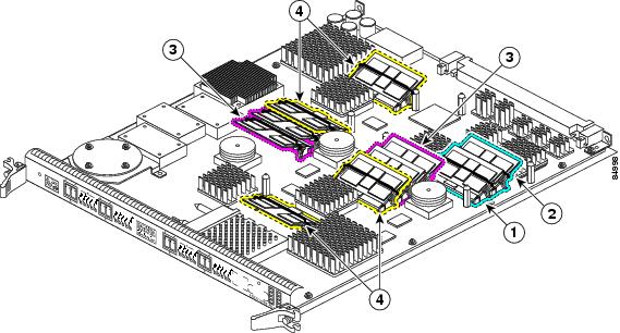
Figure 4-1 shows the small outline DIMM (SODIMM) socket locations on an ISE line card. This line card is equipped with 10 SODIMM sockets:
•![]() Two route memory SODIMM sockets
Two route memory SODIMM sockets
•![]() Four packet memory sockets (not user serviceable)
Four packet memory sockets (not user serviceable)
•![]() Four TLU/PLU memory sockets (not user serviceable)
Four TLU/PLU memory sockets (not user serviceable)
Figure 4-1 ISE Line Card Memory Locations
|
|
Route memory SODIMM0 |
|
Four packet memory SODIMM sockets (not field serviceable) |
|
|
Route memory SODIMM1 |
|
Four TLU/PLU memory SODIMM sockets (not field serviceable) |
There are two route memory sockets on ISE (Engine 3) line cards that support the addition of route memory modules. Table 4-3 describes the various memory upgrade options.
|
|
|
|
|---|---|---|
1-Port Channelized OC-12/STM-4 ISE Line Card |
• • • |
• • • • |
1 If you need to upgrade beyond 2 x 512 MB modules, you must contact the Cisco Technical Support Personnel for instructions. 2 Do not mix memory sizes. Both DIMMs must be the same size memory. 3 Requires Cisco IOS XR Release 3.2 or a later release, and you must upgrade the route processor ROMMON code to Version 1.13 or later before installing the upgraded memory. |
Line Card Memory Options
Table 4-4 lists the available route memory options for the 1-Port Channelized OC-12/STM-4 ISE Line Card. The 1-Port Channelized OC-12/STM-4 ISE Line Card is available with 512-MB route memory (MEM-LC-ISE-512) at no cost.
|
|
|
|
|
1 GB |
MEM-LC-ISE-1G1 |
2 512-MB SODIMM |
DIMM0 and DIMM1 |
1 This order number is used whether you are replacing or upgrading the route memory. The default memory on ISE line cards is 512 MB. This is provided either as two 256-MB SODIMMs or as one 512-MB SODIMM. |
Removing and Installing Line Card Memory
Before beginning the memory replacement procedures in this section, ensure that you have the proper tools and equipment at hand, and that you are using appropriate ESD-prevention equipment and techniques. This section contains the following procedures:
•![]() Checking the Installation of Line Card Memory
Checking the Installation of Line Card Memory
Refer to Figure 4-1 for the location of the memory on your line card.
Removing a SODIMM
To remove a SODIMM, follow these steps:
Step 1 ![]() Attach an ESD-preventive wrist or ankle strap and follow its instructions for use.
Attach an ESD-preventive wrist or ankle strap and follow its instructions for use.
Step 2 ![]() Place the line card on an antistatic mat so that the faceplate is nearest to you.
Place the line card on an antistatic mat so that the faceplate is nearest to you.
Step 3 ![]() Locate the route memory socket on the line card.
Locate the route memory socket on the line card.
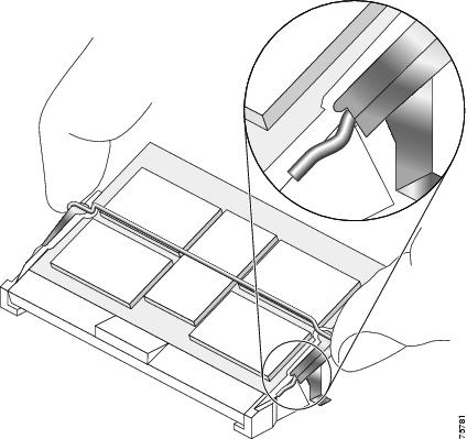
Step 4 ![]() If present, remove the SODIMM retaining clip from the memory module socket. Grasp the latch arm intersection located on each side of the clip and gently slide the clip out. (See Figure 4-2.) Save the retaining clip.
If present, remove the SODIMM retaining clip from the memory module socket. Grasp the latch arm intersection located on each side of the clip and gently slide the clip out. (See Figure 4-2.) Save the retaining clip.
Note ![]() Some line cards do not require a retaining clip.
Some line cards do not require a retaining clip.
Figure 4-2 Remove Retaining Clip from Memory Module Socket
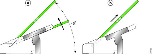
Step 5 ![]() Remove the SODIMM by gently moving the plastic latches in an outward direction, parallel to and away from the memory module, until it releases and rotates to a 45-degree angle. (See Figure 4-3 and Figure 4-4a.)
Remove the SODIMM by gently moving the plastic latches in an outward direction, parallel to and away from the memory module, until it releases and rotates to a 45-degree angle. (See Figure 4-3 and Figure 4-4a.)
Figure 4-3 Moving the Plastic Latch Away from the SODIMM
Step 6 ![]() As the SODIMM is released, it positions itself at a 45-degree angle. Gently pull the SODIMM module out of the socket. Continue to keep the module at a 45-degree angle until it is completely removed from the socket guides. (See Figure 4-4b.)
As the SODIMM is released, it positions itself at a 45-degree angle. Gently pull the SODIMM module out of the socket. Continue to keep the module at a 45-degree angle until it is completely removed from the socket guides. (See Figure 4-4b.)
Figure 4-4 Removing a 144-pin SODIMM Module
Step 7 ![]() Immediately place the SODIMM in an antistatic bag to protect it from ESD damage.
Immediately place the SODIMM in an antistatic bag to protect it from ESD damage.
Installing a SODIMM
To install a SODIMM module, follow these steps:
Step 1 ![]() Attach an ESD-preventive wrist or ankle strap and follow its instructions for use.
Attach an ESD-preventive wrist or ankle strap and follow its instructions for use.
Step 2 ![]() Place the line card on an antistatic mat so that the faceplate is nearest to you.
Place the line card on an antistatic mat so that the faceplate is nearest to you.
Step 3 ![]() If there is a retaining clip, check to make sure that it has not been damaged or bent. (See Figure 4-5.)
If there is a retaining clip, check to make sure that it has not been damaged or bent. (See Figure 4-5.)
Note ![]() Some line cards do not require a retaining clip.
Some line cards do not require a retaining clip.
Figure 4-5 SODIMM Socket Retaining Clip

Step 4 ![]() Locate the route memory socket on the line card.
Locate the route memory socket on the line card.
Step 5 ![]() Remove the new SODIMM from its protective antistatic bag.
Remove the new SODIMM from its protective antistatic bag.
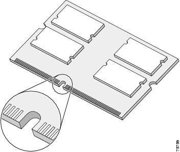
Step 6 ![]() Line up the SODIMM key with the key in the board socket. (See Figure 4-6.)
Line up the SODIMM key with the key in the board socket. (See Figure 4-6.)
Figure 4-6 SODIMM with Key in Face-up Position
Step 7 ![]() The SODIMM must be lined up at a 45-degree angle. (See Figure 4-7a.)
The SODIMM must be lined up at a 45-degree angle. (See Figure 4-7a.)
Note ![]() When the key is in the face-up position, the metal traces on the left side of the key measure 0.9 inch (23.20 mm). The metal traces on the right side of the key measure 1.29 inches (32.80 mm). The SODIMM can not be inserted until the keys are lined up properly.
When the key is in the face-up position, the metal traces on the left side of the key measure 0.9 inch (23.20 mm). The metal traces on the right side of the key measure 1.29 inches (32.80 mm). The SODIMM can not be inserted until the keys are lined up properly.
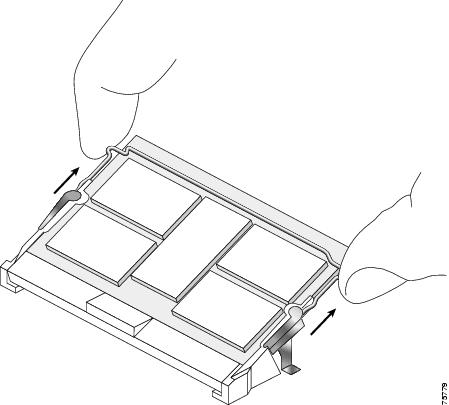
Step 8 ![]() Place both thumbs at the end of the socket and use your index fingers to guide the module into the socket until it is fully seated.
Place both thumbs at the end of the socket and use your index fingers to guide the module into the socket until it is fully seated.
Be sure that your index fingers are located on the outer corners of the SODIMM to maintain even pressure when the module is being seated in the socket.
Figure 4-7 Inserting a 144-pin SODIMM Module

Step 9 ![]() Gently press the SODIMM down using your index fingers, distributing even pressure across the module until it locks into the tabs. (See Figure 4-7b.)
Gently press the SODIMM down using your index fingers, distributing even pressure across the module until it locks into the tabs. (See Figure 4-7b.)
Step 10 ![]() Verify that the release levers are flush against the side of the socket. If they are not, the SODIMM might not be seated properly.
Verify that the release levers are flush against the side of the socket. If they are not, the SODIMM might not be seated properly.
Step 11 ![]() If the module appears misaligned, carefully remove it and reseat it, ensuring that the release lever is flush against the side of the SODIMM socket.
If the module appears misaligned, carefully remove it and reseat it, ensuring that the release lever is flush against the side of the SODIMM socket.
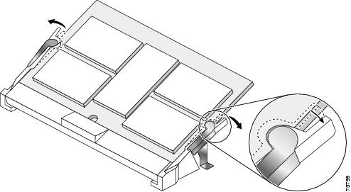
Step 12 ![]() If there is a retaining clip, insert it by sliding the clip between the metal strain relief and the plastic latch.
If there is a retaining clip, insert it by sliding the clip between the metal strain relief and the plastic latch.
(See Figure 4-8.)
Figure 4-8 Inserting the Retaining Clip
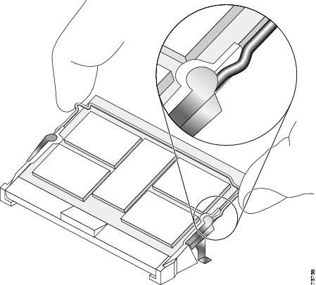
The clip is properly installed when the clip detente protrudes below the strain relief and plastic latch. (See Figure 4-9.)
Figure 4-9 Retaining Clip Completely Installed into Module Latch
Checking the Installation of Line Card Memory
After you install line card memory and reinstall the line card in the router, the router reinitializes the line card and detects the memory change as part of the reinitialization cycle. The time required for the router to initialize can vary with different router configurations and memory configurations. A router with larger SODIMMs, for example, might take longer to boot.
If the line card does not reinitialize properly after you upgrade the SODIMMs on the line card, or if the console terminal displays a checksum or memory error, verify that you installed the correct SODIMM module and that it is installed correctly on the line card.
To check the installation of line card memory, follow these steps:
Step 1 ![]() Remove the line card from the card cage as described in the "Removing a Line Card" section on page 3-3.
Remove the line card from the card cage as described in the "Removing a Line Card" section on page 3-3.
Step 2 ![]() Check the alignment of the SODIMM looking at it across the horizontal plane of the card. The SODIMM module should be aligned at the same angle as shown in Figure 4-7 and be fully inserted into its socket.
Check the alignment of the SODIMM looking at it across the horizontal plane of the card. The SODIMM module should be aligned at the same angle as shown in Figure 4-7 and be fully inserted into its socket.
If a SODIMM is not correctly aligned, remove it and reinsert it.
Step 3 ![]() Reinstall the line card in the card cage as described earlier in this publication and perform another installation check.
Reinstall the line card in the card cage as described earlier in this publication and perform another installation check.
If the card fails to restart properly after several attempts and you are unable to resolve the problem, access Cisco.com or contact your Cisco Technical Support representative for assistance. Before calling, make note of any console error messages, unusual LED states, or other router indications or behaviors that might help to resolve the problem.
Physical Layer Features
The following section provides details of 1-Port Channelized OC-12/STM-4 ISE Line Card physical layer features:
•![]() Supported and Unsupported Channelization Modes
Supported and Unsupported Channelization Modes
Supported and Unsupported Channelization Modes
The 1-Port Channelized OC-12/STM-4 ISE Line Card supports only the SONET mode of operation. The line card does not support SDH framing in the current release of Cisco IOS XR software. The following section describes:
•![]() Supported Channelization Modes
Supported Channelization Modes
•![]() Unsupported Channelization Modes
Unsupported Channelization Modes
•![]() Supported DS3 Framing Modes
Supported DS3 Framing Modes
•![]() Supported DS3 Alarms
Supported DS3 Alarms
•![]() Supported DS1 Framing Modes
Supported DS1 Framing Modes
•![]() Supported DS1 Alarms
Supported DS1 Alarms
Supported Channelization Modes
The 1-Port Channelized OC-12/STM-4 ISE Line Card supports the following channelization modes in the Cisco IOS XR Software Release 3.8.0:
•![]() CT3 Mode mapping
CT3 Mode mapping
•![]() STS-12<->STS-1<->DS3<->DS-1<->nDS-0
STS-12<->STS-1<->DS3<->DS-1<->nDS-0
•![]() VT-1.5 Mode Mapping
VT-1.5 Mode Mapping
•![]() STS-12<->STS-1<->VTG<->VT-1.5<->DS-1<->nDS-0.
STS-12<->STS-1<->VTG<->VT-1.5<->DS-1<->nDS-0.
Unsupported Channelization Modes
The 1-Port Channelized OC-12/STM-4 ISE Line Card does not support the following channelization modes in Cisco IOS XR Software Release 3.8.0:
•![]() STS-1 > E3
STS-1 > E3
•![]() E3 > E1
E3 > E1
•![]() T3 > T1
T3 > T1
•![]() STS-1 > VT2 > E1
STS-1 > VT2 > E1
•![]() AU-4 > TUG-3 > VC-3 > DS3 > T1/E1
AU-4 > TUG-3 > VC-3 > DS3 > T1/E1
•![]() AU-4 > TUG-3 > TUG-2 > VC11 > T1
AU-4 > TUG-3 > TUG-2 > VC11 > T1
•![]() AU-3 > VC-3 > E3
AU-3 > VC-3 > E3
•![]() AU-3 > TUG-2 > VC12> E1
AU-3 > TUG-2 > VC12> E1
Note ![]() The SDH is not supported for Cisco IOS XR Software Release 3.8.0.
The SDH is not supported for Cisco IOS XR Software Release 3.8.0.
Supported DS3 Framing Modes
The 1-Port Channelized OC-12/STM-4 ISE Line Card supports the following DS3 Framing modes in the Cisco IOS XR Software Release 3.8.0:
•![]() M13
M13
•![]() C-bit Parity
C-bit Parity
Note ![]() The default mode is C-bit.
The default mode is C-bit.
Supported DS3 Alarms
The 1-Port Channelized OC-12/STM-4 ISE Line Card supports the following DS3 Alarms in the CiscoIOSXR Software Release 3.8.0:
•![]() AIS - Alarm Indication Signal
AIS - Alarm Indication Signal
•![]() LOF - Loss of Frame Failure
LOF - Loss of Frame Failure
•![]() LOS - Loss of Signal Failure
LOS - Loss of Signal Failure
•![]() RAI - Remote Alarm Indication
RAI - Remote Alarm Indication
Supported DS1 Framing Modes
The 1-Port Channelized OC-12/STM-4 ISE Line Card supports the following DS1 Framing Modes in the Cisco IOS XR Software Release 3.8.0:
•![]() SF - Super Frame
SF - Super Frame
•![]() ESF - Extended Super Frame
ESF - Extended Super Frame
Note ![]() The default mode is ESF.
The default mode is ESF.
Supported DS1 Alarms
The 1-Port Channelized OC-12/STM-4 ISE Line Card supports the following DS1 Alarms in CiscoIOSXR Software Release 3.8.0:
•![]() AIS
AIS
•![]() LOS
LOS
•![]() Red - Near end LOF
Red - Near end LOF
•![]() Yellow - Far end LOF
Yellow - Far end LOF
Note ![]() The 1-Port Channelized OC-12/STM-4 ISE Line Card supports MLPPP. All member links in a multilink must be full T1 and must be within the same line card. The 1-Port Channelized OC-12/STM-4 ISE Line Card supports up to 12 member links in a multilink.
The 1-Port Channelized OC-12/STM-4 ISE Line Card supports MLPPP. All member links in a multilink must be full T1 and must be within the same line card. The 1-Port Channelized OC-12/STM-4 ISE Line Card supports up to 12 member links in a multilink.
SONET Loopback
The following types of loopback are supported at the SONET line level:
•![]() Local Line Loopback
Local Line Loopback
•![]() Network Line Loopback
Network Line Loopback
SONET paths cannot be individually configured for loopback.
Encapsulation Method Support
The following encapsulation methods are supported by the 1-Port Channelized OC-12/STM-4 ISE Line Card on channelized serial interfaces:
•![]() High-level Data Link Control (HDLC)
High-level Data Link Control (HDLC)
•![]() Point to Point Protocol (PPP)
Point to Point Protocol (PPP)
•![]() Frame Relay
Frame Relay
•![]() Multilink PP (MLPPP)
Multilink PP (MLPPP)
Note ![]() The default encapsulation method on a channelized serial interface is Cisco HDLC.
The default encapsulation method on a channelized serial interface is Cisco HDLC.
Support for APS
The 1-Port Channelized OC-12/STM-4 ISE Line Card supports Multiroute-APS. The SONET APS as specified in GR-253-CORE is not supported.
Note ![]() The 1-Port Channelized OC-12/STM-4 ISE Line Card does not support FEAC, MDL, or DS3 BERT.
The 1-Port Channelized OC-12/STM-4 ISE Line Card does not support FEAC, MDL, or DS3 BERT.
DS1 BERT Support
BERT (Bit-Error Rate Testing) tests are used for analyzing quality and for problem resolution of digital transmission equipment. BERT tests the quality of an interface by directly comparing a pseudo-random or repetitive test pattern with an identical locally generated test pattern. BERT tests can be run on T3/E3 interfaces.
The BERT operation is data-intrusive. Regular data cannot flow on the T3/E3 path while the test is in progress. The path is reported to be in alarm state when BERT is in progress and restored to a normal state after BERT has been terminated.
The supported DS-1 BERT patterns on the line card are as follows:
•![]() All 0's
All 0's
•![]() All 1's
All 1's
•![]() Alternating 0s and 1s
Alternating 0s and 1s
•![]() 1-in-8
1-in-8
•![]() 3-in-24
3-in-24
•![]() 2^11-1
2^11-1
•![]() 2^15-1 O.151
2^15-1 O.151
•![]() 2^20-1 O.153
2^20-1 O.153
•![]() 2^20-1 QRSS
2^20-1 QRSS
•![]() 2^23-1 O.151
2^23-1 O.151
It is also possible to insert single errors into the patterns.
Supported Loopbacks
The 1-Port Channelized OC-12/STM-4 ISE Line Card supports different loopbacks at SONET, DS-3/E3 level.
DS-3 supports following loopbacks:
•![]() Local loopback
Local loopback
•![]() Network loopback
Network loopback
SONET supports following loopbacks:
•![]() Local loopback
Local loopback
•![]() Network line loopback
Network line loopback
DS1 supports following loopbacks:
•![]() Local loopback
Local loopback
•![]() Network line loopback
Network line loopback
•![]() Network payload loopback
Network payload loopback
•![]() Remote line FDL ANSI
Remote line FDL ANSI
•![]() Remote line FDL BellCore
Remote line FDL BellCore
•![]() Remote payload FDL ANSI
Remote payload FDL ANSI
Regulatory, Compliance, and Safety Information
This section includes regulatory, compliance, and safety information.
Translated Safety Warnings and Agency Approvals
The complete list of translated safety warnings and agency approvals is available in the Regulatory Compliance and Safety Information for Cisco 12000 Series Internet Routers publication.
(Document Number 78-4347-19.)
Electromagnetic Compatibility Regulatory Statements
FCC Class A Compliance
This equipment has been tested and found to comply with the limits for a Class A digital device, pursuant to part 15 of the FCC rules. These limits are designed to provide reasonable protection against harmful interference when the equipment is operated in a commercial environment. This equipment generates, uses, and can radiate radio-frequency energy and, if not installed and used in accordance with the instruction manual, may cause harmful interference to radio communications. Operation of this equipment in a residential area is likely to cause harmful interference, in which case users will be required to correct the interference at their own expense.
Modifying the equipment without Cisco's authorization may result in the equipment no longer complying with FCC requirements for Class A digital devices. In that event, your right to use the equipment may be limited by FCC regulation and you may be required to correct any interference to radio or television communication at your own expense.
You can determine whether your equipment is causing interference by turning it off. If the interference stops, it was probably caused by the Cisco equipment or one of its peripheral devices. If the equipment causes interference to radio or television reception, try to correct the interference by using one or more of the following measures:
•![]() Turn the television or radio antenna until the interference stops.
Turn the television or radio antenna until the interference stops.
•![]() Move the equipment to one side or the other of the television or radio.
Move the equipment to one side or the other of the television or radio.
•![]() Move the equipment farther away from the television or radio.
Move the equipment farther away from the television or radio.
•![]() Plug the equipment into an outlet that is on a different circuit from the television or radio. (That is, make certain the equipment and the television or radio are on circuits controlled by different circuit breakers or fuses.)
Plug the equipment into an outlet that is on a different circuit from the television or radio. (That is, make certain the equipment and the television or radio are on circuits controlled by different circuit breakers or fuses.)
CISPR 22
This apparatus complies with CISPR 22/EN55022 Class B radiated and conducted emissions requirements.
Canada
English Statement of Compliance
This class A digital apparatus complies with Canadian ICES-003.
French Statement of Compliance
Cet appareil numérique de la classe A est conforme à la norme NMB-003 du Canada.
Europe (EU)
This apparatus complies with EN55022 Class B and EN55024 standards when used as ITE/TTE equipment, and EN300386 for Telecommunications Network Equipment (TNE) in both installation environments, telecommunication centers and other indoor locations.
Class A Notice for Hungary


Class A Notice for Taiwan and Other Traditional Chinese Markets


VCCI Class A Notice for Japan


Class A Notice for Korea


Laser Safety
Channelized line cards are equipped with a Class 1 laser, which emits invisible radiation. Do not stare into operational line card ports. The following laser warnings apply to the channelized and electrical interface line card:
•![]() Class 1 Laser Product Warning
Class 1 Laser Product Warning
Class 1 Laser Product Warning
The following warning applies to single-mode SR, IR, and LR optics:

Warning ![]() Class 1 laser product.
Class 1 laser product.
General Laser Warning
The following warning applies to the channelized and electrical interface line card:
Warning ![]() Invisible laser radiation can be emitted from the aperture of the port when no cable is connected. Avoid exposure to laser radiation and do not stare into open apertures.
Invisible laser radiation can be emitted from the aperture of the port when no cable is connected. Avoid exposure to laser radiation and do not stare into open apertures.
For translated safety warnings, refer to the Regulatory Compliance and Safety Information for
Cisco 12000 Series Internet Routers publication (Document Number 78-4347-19).
 Feedback