Configuration

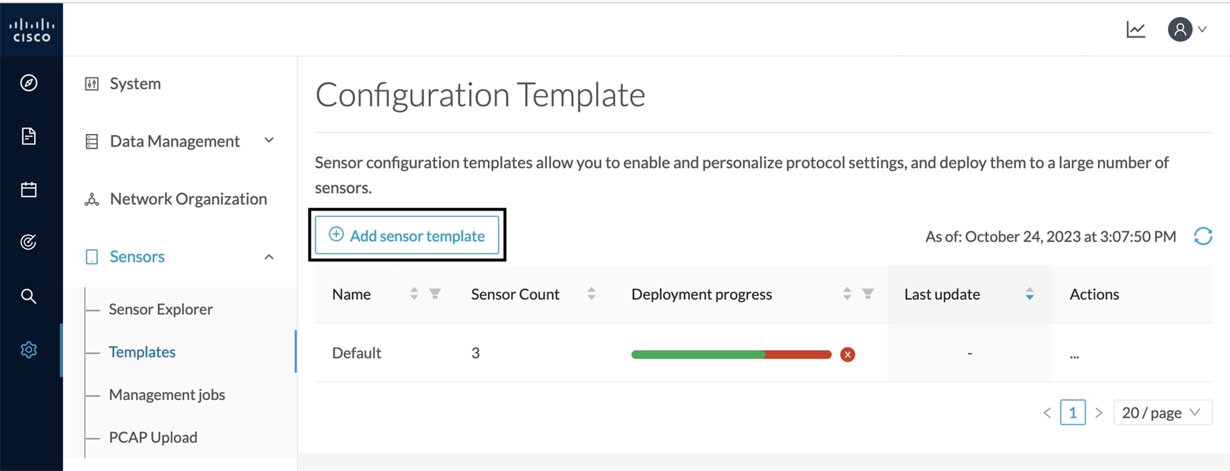
Configure Active Discovery

Once the sensor is connected, you can change the Active Discovery's network interface so it uses the Collection network interface instead, and add several network interfaces for the sensor to perform Active Discovery on several subnetworks at the same time.

Procedure


Step 1

Click the sensor to configure and click the Active Discovery button on its right side panel.

The Active Discovery configuration appears with the interface currently set.

Step 2

Select Use collection interface for the Active Discovery to use the Collection network interface.

To add a network interface to Active Discovery for the sensor to perform active monitoring on another subnetwork:

Step 3

Add a new network interface by clicking the corresponding button.

Step 4

Fill the following parameters to set dedicated network interfaces:

  • IP address

  • Prefix length

  • VLAN number

Step 5

Click Add.

You can add as many network interfaces as needed.

Step 6

When you are done, click Configure.

A message saying that the configuration has been applied successfully appears.


Configure sensor configuration template

Templates

This page allows you to create and set templates with protocol configurations and assign them to specific sensors.

Sensor templates contain protocol configurations which allow you:

  • To enable or disable protocol DPI (Deep Packet Inspection) engines.

  • To map UDP and TCP ports for each protocol’s packet received by the sensor.

By enabling/disabling a protocol DPI engine you can decide which protocols will be analyzed.

Disabling a protocol DPI engine avoid false positives in Cisco Cyber Vision, that is when a protocol appears on the user interface when it’s actually not the case because same UDP/TCP ports can be used by other non-standardized protocols.

Some protocols are disabled in the Default template because they are not commonly used or used in specific fields such as transportation. The Default template is applied on all compatible sensors.

As previously mentioned, UDP/TCP ports default configurations are mostly standardized, but conflicts still exist among field-specific protocols or with limited usage. Mapping UDP/TCP port numbers will allow packets to be sent to the correct DPI engine so they can be accurately analyzed and correctly represented in the user interface.

If the protocol’s packet is sent to the wrong port, related information will end up in Security Insights/Flows with no tag.

A sensor can be associated with a single template only. Deployment of the template can fail:

  • if the sensor is disconnected,

  • if there is connection issues,

  • if the sensor version is too old.

Create templates

Procedure


Step 1

In Cisco Cyber Vision, navigate to Admin > Sensors > Templates.

Step 2

Click Add sensor template.

The Create sensor template window pops up.

Step 3

Add a name to the template. You can also add a description.

Step 4

Click Next.

The list of protocol DPI engines with their basic configurations appears.

Step 5

In the search bar, type the protocol you want to configure.

In our example, we will add a port to the OPCUA default settings.

Step 6

Under the Port Mapping column, click the pen button to edit its settings.

The protocol's port mapping window pops up.

Step 7

Write down the port number you want to add and hit enter.

Step 8

Click OK.

The port number is added to the protocol's default settings.

Toggling ON the Displayed modified only button allows you to quickly find this protocol.

Step 9

Click Next.

Step 10

Select the sensor(s) you want to apply the template to.

Step 11

Click Next.

Step 12

Check the template configurations and Confirm its creation.

The configuration is sent to the sensors. Configuration deployment will take a few moments.

The OPCUA template appears in the template list with its two assigned sensors.


Set a capture mode

The Capture mode feature lets you choose which network communications will be analyzed by the sensors. You can set it by clicking an online sensor in the sensors list of the Sensor Explorer page or during a sensor installation.

Setting the capture mode on a sensor from the right side panel:

Capture modes:

The aim is mainly to focus the monitoring on relevant traffic but also to reduce the load on the Center.

For example, a common filter in a firewall can consist of removing the network management flows (SNMP). This can be done by setting a filter like "not (port 161 and host 10.10.10.10)" where "10.10.10.10" is the network management platform.

Using Capture mode Cisco Cyber Vision performance can be improved on large networks.

Capture modes operate because of filters applied on each sensor. Filters are set to define which types of incoming packets are to be analyzed by the sensors. You can set a different filter on each sensor according to your needs.

You can set the capture mode in the installation wizard when enrolling the sensors during the Center installation. This option is recommended if you already know which filter to set. Otherwise, you can change it at any time through the Sensor Explorer page in the GUI (provided that the SSH connection is allowed from the Center to the sensors).


Note


You can set a capture mode to offline sensors from a file containing the filter and registered on the USB drive. This will be then plugged on the Offline USB port of the device. For more information about setting a capture mode on an offline sensor contact the support.

The different capture modes are:

  • ALL: No filter is applied. The sensor analyzes all incoming flows and they will all be stored inside the Center database.

  • OPTIMAL (Default): The applied filter selects the most relevant flows according to Cisco expertise. Multicast flows are not recorded. This capture mode is recommended for long term capture and monitoring.

  • INDUSTRIAL ONLY: The filter selects industrial protocols only like modbus, S7, EtherNet/IP, etc. This means that IT flows of the monitored network won't be analyzed by the sensor and won't appear in the GUI.

  • CUSTOM (advanced users): Use this capture mode if you want to fully customize the filter to be applied. To do so you will need to use the tcpdump syntax to define the filtering rules.