Installation

Procedure with the Cisco Cyber Vision sensor management extension

After the Initial configuration, proceed to the steps described in this section.


Note


To be able to use the Cisco Cyber Vision sensor management extension, an IP address reachable by the Center Collection interface must be set on the Collection VLAN.

Note


Since the extension deployment based on HTTPS, we should allow the flow to proceed as follows:
  • For IEXxxx/CAT9k /IRxx : port TCP 443

  • For IC3k : port TCP 8443

We can use an Access Control List (ACL) on IOS XE devices to limit access from the Cyber Vision.

Configuration example for IOS XE devices: Filter Traffic Destined to Cisco IOS XE Devices WebUI Using an Access List - Cisco

ip http access-class SOME_ID 
ip http secure-server 
! 
access-list SOME_ID permit CENTER_ETH0_IP CENTER_ETH0_WILDCARDMASK 
 
 
Where CENTER_ETH0_IP is the administration IP address of your Cyber Vision center (eth0).

Install the sensor management extension

To install the sensor management extension, you must:

Procedure


Step 1

Retrieve the extension file (i.e. CiscoCyberVision-sensor-management-<version>.ext) from cisco.com.

Step 2

Access the Extension administration page in Cisco Cyber Vision.

Step 3

Import the extension file.

Once the sensor management extension is installed, you will find a new management job under the sensor administration menu (Management jobs), and the Install via extension button will be enabled in the Sensor Explorer page.


Management jobs

As some deployment tasks on sensors can take several minutes, this page shows the jobs execution status and advancement for each sensor deployed with the sensor management extension.

This page is only visible when the sensor management extension is installed in Cisco Cyber Vision.

You will find the following jobs:

  • Single deployment

    This job is launched when clicking the Deploy Cisco device button in the sensor administration page, that is when a new IOx sensor is deployed.

  • Single redeployment

    This job is launched when clicking the Reconfigure Redeploy button in the sensor administration page, that is when deploying on a sensor that has already been deployed. This option is used for example to change the sensor's parameters like enabling active discovery.

  • Single removal

    This job is launched when clicking the Remove button from the sensor administration page.

  • Update all devices

    This job is launched when clicking the Update Cisco devices button from the sensor administration page. A unique job is created for all managed sensors that are being updated.

If a job fails, you can click on the error icon to view detailed logs.

Create a sensor in the sensor management extension

Procedure


Step 1

In Cisco Cyber Vision, navigate to Admin > Sensors > Sensor Explorer and click Install sensor, then Install via extension.

Step 2

Fill the requested fields so Cisco Cyber Vision can reach the device:

  • IP address: admin address of the device.

  • Port: management port (443).

  • Login: user with the admin rights of the device.

  • Password: password of the admin user.

  • Capture Mode: Optionally, select a capture mode.

Step 3

Click Connect.

The Center will join the device and the second parameter list will be displayed. For this step to succeed, the device needs to be reachable by the Center on its eth1 connection.


Configure a sensor in the sensor management extension

If the Center can join the switch, the following form appears:

Form for the Cisco IE3x00 and the Cisco IE9x00:

Form for the Cisco Catalyst 9x00 with RSPAN configuration available:

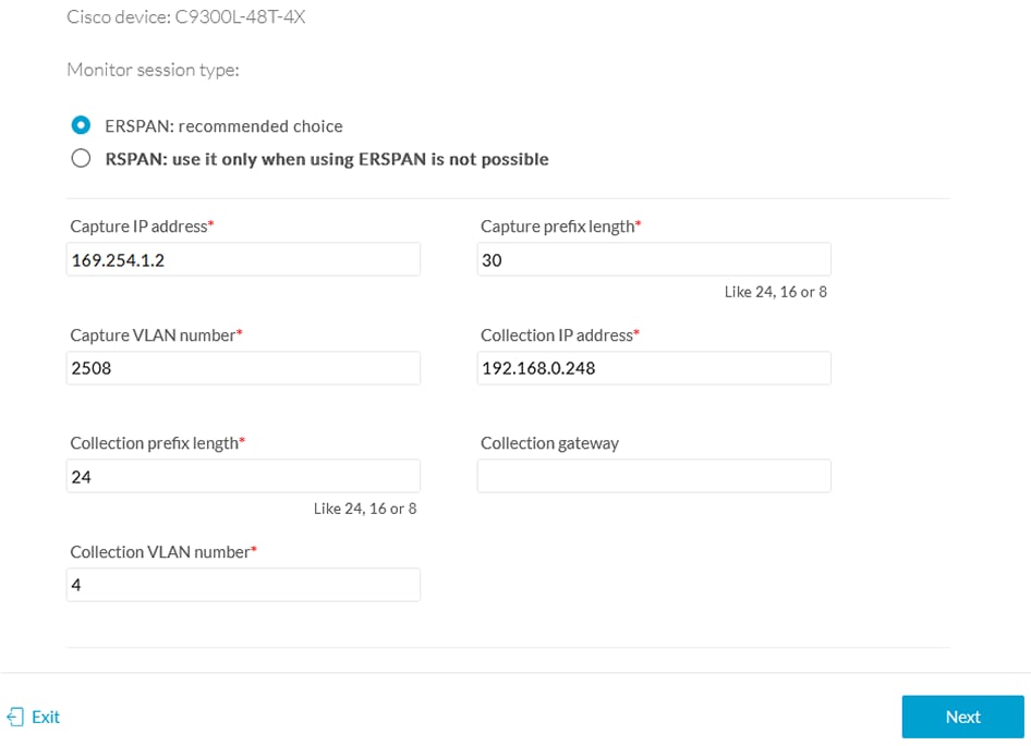
While some parameters are filled automatically, you can still change them if necessary.

Procedure


Step 1

Fill the following parameters for the Collection interface:

  • Capture IP address: IP address destination of the monitor session in the sensor

  • Capture prefix length: mask of the capture IP address

  • Capture VLAN number: VLAN of the monitor session in the sensor

  • Collection IP address: IP address of the sensor in the device

  • Collection prefix length: mask of the Collection IP address

  • Collection gateway: gateway of the Collection IP address

  • Collection VLAN number: VLAN of the sensor

Step 2

Click Next.

Step 3

Active Discovery:

If you want to enable Active Discovery on the sensor, select Passive and Active Discovery.

You can:

  • use the sensor Collection interface by selecting it:

  • add new network interfaces filling the following parameters to set dedicated network interfaces and clicking Add:

    • IP address

    • Prefix length

    • VLAN number

Step 4

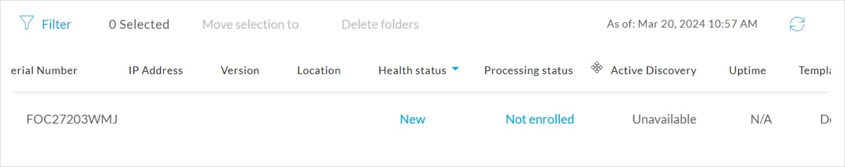
Click Deploy.

The Center starts deploying the sensor application on the target equipment. This can take a few minutes. You can go to the Management jobs page to check the deployment advancements.

Once the deployment is finished, a new sensor appears in the sensors list.

The sensor's status will eventually turn to connected.

If the Active Discovery has been enabled and set -that is if the option Passive and Active Discovery was selected when configuring the sensor in the sensor management extension- the sensor is displayed as below with Active Discovery's status as Enabled.


Configure Active Discovery

Once the sensor is connected, you can change the Active Discovery's network interface so it uses the Collection network interface instead, and add several network interfaces for the sensor to perform Active Discovery on several subnetworks at the same time.

Procedure


Step 1

Click the sensor to configure and click the Active Discovery button on its right side panel.

The Active Discovery configuration appears with the interface currently set.

Step 2

Select Use collection interface for the Active Discovery to use the Collection network interface.

To add a network interface to Active Discovery for the sensor to perform active monitoring on another subnetwork:

Step 3

Add a new network interface by clicking the corresponding button.

Step 4

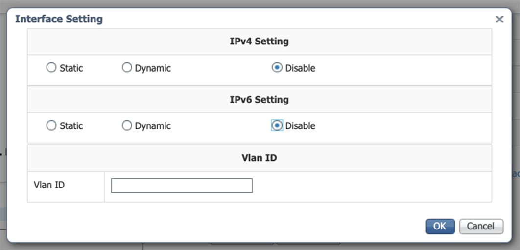
Fill the following parameters to set dedicated network interfaces:

  • IP address

  • Prefix length

  • VLAN number

Step 5

Click Add.

You can add as many network interfaces as needed.

Step 6

When you are done, click Configure.

A message saying that the configuration has been applied successfully appears.


Procedure with the Local Manager

After the Initial configuration, proceed to the steps described in this section.

Access the Local manager

  1. Open a browser and navigate to the IP address you configured on the interface you are connected to.

  2. Log in using the Local Manager user account and password.

    For example: Cisco IE3300 10G/IE3400

  3. Once logged into the Local Manager, navigate to Configuration > Services > IOx.

    For example: Cisco IE3300 10G/IE3400

  4. Log in using the user account and password.

Install the sensor virtual application

Once logged in, the following menu appears:

  1. Click Add New.

  2. Add an Application id name (e.g. CCVSensor).

  3. Select the application archive file

    • "CiscoCyberVision-IOx-aarch64-xxx.tar" for the Cisco IE3300/IE3400/IE9300

    • "CiscoCyberVision-IOx-Active-Discovery-aarch64.tar" for the Cisco IE3300/IE3400/IE9300 with Active Discovery

    • "CiscoCyberVision-IOx-x86-64-xxx.tar" for the Cisco Catalyst 9300

    • "CiscoCyberVision-IOx-Active-Discovery-x86-64.tar" for the Cisco Catalyst 9300

    The installation takes a few minutes.

    When the application is installed, the following message is displayed:

Configure the sensor virtual application (IE3x00/IE9x00)

  1. Click Activate to launch the configuration of the sensor application.

  2. Change the disk size from the default size to 1248 MB. The disk size must not be larger than this.

    If the field is grayed out, change the profile to custom to change the disk value.

  3. Bind the interfaces in the container to an interface on the host in Network Configuration. Start with eth0 by clicking edit in the eth0 line.

  4. Click Interface Setting.

  5. Apply the following configurations:

    • Select Static

    • IP/Mask: IP and mask of the sensor

    • Default gateway: IP address of the Center

    • Vlan ID, which is defined below, is the VLAN in the Cisco IE3300 10G/IE3400 dedicated to the Collection network interface (link between the Center and the sensors), e.g. 507.

  6. IPV6 must be set to Disable.

  7. Click OK twice.

  8. Click OK again on the popup.

  9. Then, apply the following parameters to eth1:

    • Select Static.

    • IP/Mask: the IP and mask of the sensor for the mirrored traffic.

    • Vlan ID, which is defined below, is the VLAN in the Cisco IE3300 10G/IE3400/IE9300 dedicated to traffic mirroring.

  10. IPV6 must be set to Disable.

  11. If configuring a sensor with Active Discovery, you must set an additional interface (eth2 without IP address) dedicated to this feature.

  12. Click Interface Setting for eth2 and set IPV4 and IPV6 as Disable. Click OK to confirm.

  13. Click the Activate App button.

    The operation takes several minutes.

    The application status changes to "RUNNING":

Configure the sensor virtual application (Catalyst 9x00)

  1. Click Activate to launch the configuration of the sensor application.

  2. Change the resource profile and advanced setting:
    • If you are using SSD:

      1. Increase the disk size to at least 80,000 MB and it should not be smaller than that.

      2. Add "--rm" in advanced settings - Docker options.

  3. Bind the interfaces in the container to an interface on the host in Network Configuration. Start with eth0 by clicking edit in the eth0 line.

  4. Select the mgmt-bridge300 entry in the interface list.

  5. Click Interface Setting.

  6. Apply the following configurations:

    • Select Static

    • IP/Mask: the IP and mask of the sensor

    • Default gateway: the IP address of the Center

    • Vlan ID, which is defined below, is the VLAN in the Cisco Catalyst 9300 dedicated to the Collection network interface (link between the Center and the sensors), e.g. 507.

  7. IPV6 must be set to Disable.

  8. Click OK twice.

  9. Click OK again on the following popup.

  10. Apply the following configurations to eth1:

    • Set IPv4 as Static and the IP and mask of the sensor for mirrored traffic.

    • Disable IPv6.

    • Set the VLAN id.

    • Set the mirror mode as enabled.

  11. Click OK until you come back to the screen below.

  12. If configuring a sensor with Active Discovery, you must set an additional interface (eth2 without IP address) dedicated to this feature. Then, click Interface Setting for eth2 and set IPV4 and IPV6 as Disable. Click OK to confirm.

  13. Click the Activate App button.

    The operation takes several seconds.

  14. Click Applications to display the application status:

  15. The application is activated and needs to be started. To do so, click the Start button.

The operation takes several seconds.

The application status changes to "RUNNING".

Generate the provisioning package

  1. In Cisco Cyber Vision, navigate to Admin > Sensors > Sensor Explorer and click Install sensor, then Manual install.

    The manual install wizard appears.

  2. Select Cisco IOx Application and click Next.

  3. Fill the fields to configure the sensor provisioning package:

    • The serial number of the hardware.

    • Center IP: leave blank.

    • Gateway: add if necessary.

    • Optionally, select a capture mode.

    • Optionally, select RSPAN (only with Catalyst 9x00 and if using ERSPAN is not possible).

  4. Click Create sensor.

  5. Click the link to download the provisioning package.

    This will download the provisioning package which is a zip archive file with the following name structure: sbs-sensor-config-<serialnumber>.zip (e.g. "sbs-sensor-configFCW23500HDC.zip").

  6. Click Finish.

  7. A new entry for the sensor appears in the Sensor Explorer list.

    The sensor status will switch from Disconnected to New.

Import the provisioning package

  1. In the Local manager, in the IOx configuration menu, click Manage.

    Cisco IE3400:

    Cisco Catalyst 9300:

  2. Navigate to App_DataDir.

    For example Cisco IE3400:

  3. Click Upload.

  4. Choose the provisioning package downloaded (i.e. "sbs-sensor-config-FOC2334V01X.zip") and add the exact file name in the path field (i.e. "sbs-sensor-config-FOC2334V01X.zip").

  5. Click OK.

    A popup indicating that Cisco Cyber Vision has been deployed successfully appears.

  6. Click OK.

Procedure with the CLI

After the Initial configuration, proceed to the steps described in this section.

Configure the sensor application


Note


In this section, "CCVSensor" is used as the appid.
  1. Connect to the device through SSH or a console.

  2. Configure the application payload by typing the following commands.

    To enable Active Discovery, you must add guest-interface 2 (in bold in the examples below).

    Cisco IE3300 10G/IE3400:

    enable
    configure terminal
    app-hosting appid CCVSensor
    app-vnic AppGigabitEthernet trunk
    guest-interface 2
    vlan 507 guest-interface 0
    guest-ipaddress 192.168.69.208 netmask 255.255.255.0
    vlan 2508 guest-interface 1
    guest-ipaddress 169.254.1.2 netmask 255.255.255.0
    app-default-gateway 192.168.69.1 guest-interface 0
    app-resource profile custom
    persist-disk 2048
    cpu 1400
    memory 1248
    vcpu 2
    end

    Cisco IE9300:

    enable
    configure terminal
    app-hosting appid CCVSensor
     app-vnic AppGigabitEthernet trunk
    guest-interface 2
      vlan 507 guest-interface 0
       guest-ipaddress 192.168.69.90 netmask 255.255.255.0
      vlan 2508 guest-interface 1
       guest-ipaddress 169.254.1.2 netmask 255.255.255.252
     app-default-gateway 192.168.69.190 guest-interface 0
     app-resource docker
      run-opts 1 --rm
     app-resource profile custom
      cpu 1000
      memory 862
      persist-disk 4000
    end

    Cisco Catalyst 9300:

    enable
    configure terminal
    app-hosting appid CCVSensor
    app-vnic AppGigabitEthernet trunk
    guest-interface 2
    vlan 507 guest-interface 0
    guest-ipaddress 192.168.69.210 netmask 255.255.255.0
    vlan 2508 guest-interface 1
    mirroring
    guest-ipaddress 169.254.1.2 netmask 255.255.255.0
    app-default-gateway 192.168.69.1 guest-interface 0
    app-resource profile custom
    persist-disk 8192
    cpu 7400
    memory 2048
    vcpu 2
    end

For the app-resource profile's custom values, refer to the result of the show app-hosting resource command.

In this example, all maximum values are used for:

  • the CPU (CPU available units, here 1400 for the Cisco IE3300 10G/IE3400, 1000 for the Cisco IE9300, and 7400 for the Cisco Catalyst 9300)

  • the VCPU (here 2), the memory (Memory available, here 2048)

  • the disk (only 2048 MB and 8192 MB respectively are used to let space for application updates)

Install the sensor application

The sensor package is to be retrieved on cisco.com. The file has the following name structure:

  • CiscoCyberVision-IOx-aarch64-<VERSION>.tar (Cisco IE3300 10G/IE3400/IE9300).

  • CiscoCyberVision-IOx-x86-64-<VERSION>.tar (Cisco Catalyst 9300).

  1. Copy the package to a USB key or in the flash memory.

  2. Type the following commands on the CLI:

    enable
    app-hosting install appid CCVSensor package usbflash0:<FILENAME>.tar

    Cisco IE3300 10G/IE3400/IE9300:

    Cisco Catalyst 9300:


    Note


    Adjust "usbflash0:" in accordance with the sensor package's localization (USB port or flash memory).

    Note


    Replace "CiscoCyberVision-IOx-aarch64-<VERSION>.tar" with the right filename.
  3. Check that the application is in "DEPLOYED" state:

    show app-hosting list

    For example: Cisco IE3400

  4. Activate the application using the following command:

    app-hosting activate appid CCVSensor

    For example: Cisco IE3400

  5. Start the application using the following command:

    app-hosting start appid CCVSensor

    For example: Cisco IE3400:

Generate the provisioning package

  1. In Cisco Cyber Vision, navigate to Admin > Sensors > Sensor Explorer and click Install sensor, then Manual install.

    The manual install wizard appears.

  2. Select Cisco IOx Application and click Next.

  3. Fill the fields to configure the sensor provisioning package:

    • The serial number of the hardware.

    • Center IP: leave blank.

    • Gateway: add if necessary.

    • Optionally, select a capture mode.

    • Optionally, select RSPAN (only with Catalyst 9x00 and if using ERSPAN is not possible).

  4. Click Create sensor.

  5. Click the link to download the provisioning package.

    This will download the provisioning package which is a zip archive file with the following name structure: sbs-sensor-config-<serialnumber>.zip (e.g. "sbs-sensor-configFCW23500HDC.zip").

  6. Click Finish.

  7. A new entry for the sensor appears in the Sensor Explorer list.

    The sensor status will switch from Disconnected to New.

Copy the sensor application provisioning package

  • Copy the provisioning package from the USB key to the application using the following command:

    app-hosting data appid CCVSensor copy usbflash0:sbs-sensor-config-<SERIAL-NUMBER>.zip sbs-sensor-config-<SERIAL-NUMBER>.zip

    For example: Cisco IE3400

  • A new entry for the sensor appears in the Sensor Explorer list.

    The sensor status will switch from Disconnected to Connected.

Final step

In the sensor's CLI save the product's configuration by typing the following command:

write mem