Mount the Chassis

Unpack and Inspect the Chassis


Note


The chassis is thoroughly inspected before shipment. If any damage occurred during transportation or any items are missing, contact your customer service representative immediately. Keep the shipping container in case you need to send the chassis back due to damage.


See Package Contents for a list of what shipped with the chassis.

Procedure


Step 1

Remove the chassis from its cardboard container and save all packaging material.

Step 2

Compare the shipment to the equipment list provided by your customer service representative. Verify that you have all items.

Step 3

Check for damage and report any discrepancies or damage to your customer service representative. Have the following information ready:

  • Invoice number of shipper (see the packing slip)

  • Model and serial number of the damaged unit

  • Description of damage

  • Effect of damage on the installation


Desktop-Mount the Chassis

You can mount the chassis on a desktop by placing it on a desk in a horizontal position. Make sure there are no blockages or obstructions within one inch of the top of the chassis or within .5 inches of the sides and back, so that nothing interferes with cooling. Do not remove the rubber feet included with the chassis. They are also needed for proper cooling.

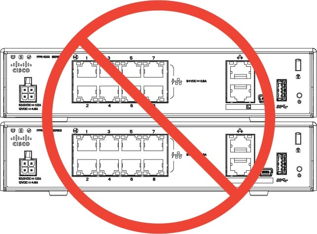
Figure 1. Desk Top Mount the Chassis

Caution


Do not stack one chassis on top of another chassis. If you stack the units, they will overheat, which causes the units to power cycle.


What to do next

See Install the FIPS Opacity Shield if you need to install a FIPS opacity shield.

Install the cables according to your default software configuration as described in the Cisco Firepower 1010 Getting Started Guide.

Wall-Mount the Chassis

You can purchase an optional wall-mount kit. You can wall-mount the chassis left-, right-, or rear panel-side up. You can use the wall-mount bracket to mark the holes for mounting it on the wall. The wall-mount bracket is 7.682 x 6 inches. You need to make two level marks on the wall where you want to hang the chassis. For vertical orientation (rear panel up), the holes should be 6.826 inches apart. For side to side orientation, the holes should be 5.154 inches apart.

The wall-mount kit (part number 69-100647-01) contains the following items:

  • Wall-mount bracket (part number 700-118506-01)

  • Three Phillips M3 x 6-mm screws (part number 48-0460-01)

  • Two Phillips #6 x 1¼-inch screws (part number 48-2289-01)

  • One #8 wall anchor kit with screws (part number 51-4718-01)

Follow these steps to mount your chassis on a wall.

Procedure


Step 1

Choose an orientation (left-, right-, or rear panel-side up) and a location on the wall for the chassis.

Step 2

Use a pencil, ruler, and level to mark locations for the two mounting screws (#6 x 1¼ inch). You can use the wall-mount bracket itself to mark either the top holes or the side holes.

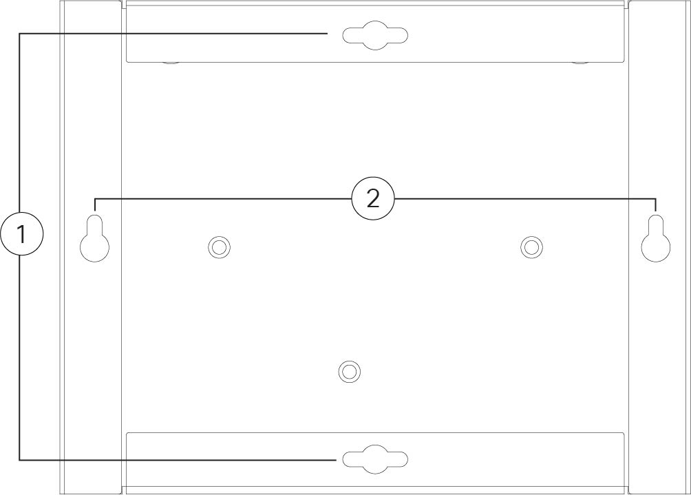
Figure 2. Wall-Mount Bracket

1

Horizontal mounting

2

Vertical mounting

Step 3

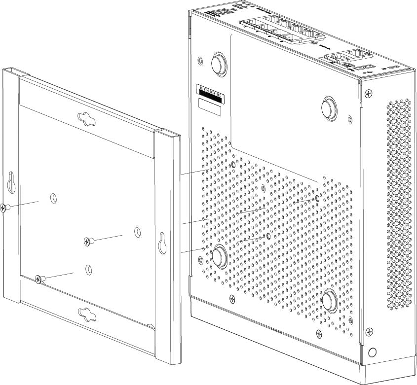
Attach the wall-mount bracket to the chassis using the three Phillips M3 x 6-mm screws.

Figure 3. Attach the Wall-Mount Bracket to the Chassis

Step 4

Use the two #6 x 1¼-inch screws to drill into a stud, or use the anchors (#8 wall screw) from the dry-wall kit to hang it into dry wall.

If you are mounting the chassis onto something other than drywall, such as wood or sheet metal, anchors may not be required.

Step 5

Drill a hole into the wall at each mark that you made in Step 2.

These holes should be slightly smaller in diameter than anchors if you are using them. The recommended drill hole size is 3/16 inches.

Step 6

Insert the anchors into the holes if needed, and be sure they are properly seated.

Step 7

Fasten each screw into its anchor until it protrudes about ¼ inch.

Step 8

Pick up the chassis, align the screws in the anchors with the holes in the bottom of the wall-mount bracket, move the chassis toward the wall until the screw heads are in the wall-mount bracket, and then slide it down until it rests on the screws.

Caution


Do not mount the chassis with the rear panel facing downward. This orientation is not supported.

Step 9

To uninstall the chassis from the wall mount, slide the wall-mounted chassis from the wall, and remove the three screws from the bottom of the chassis.


What to do next

If you are installing a FIPS cover on the chassis, follow the steps in Install the FIPS Opacity Shield.

Install the cables according to your default software configuration as described in the Cisco Firepower 1010 Getting Started Guide.

Rack-Mount the Chassis

The rack-mount shelf fits into a 2 RU rack. The rack-mount shelf is 3.06 x 17.40 x 19.70 inches (H x W x D). The rack-mount kit (800-107605-01) contains the following items:


Note


There are two sets of four screws that you can use to secure the chassis to your rack. Chose the screws that fit your rack.
  • Rack shelf (part number 700-122662-01)

  • Two sliding rack trays (part number 800-107648-01)

  • Two cable guides (part number 700-122664-01)

  • Twelve Phillips M3 x 7-mm screws (part number 48-1921-01); use these screws to install the cable guides and to secure the rack shelf onto the chassis.

  • Four Phillips 12-24 x 0.75-inch screws (part number 48-0440-01); depending on your rack type, use these screws to secure the sliding-rack tray to your rack.

  • Four Phillips 10-32 x 0.75-inch screws (part number 48-0441-01); depending on your rack type, use these screws to secure the sliding-rack tray to your rack.

Procedure


Step 1

Install the cable guides on the rack shelf:

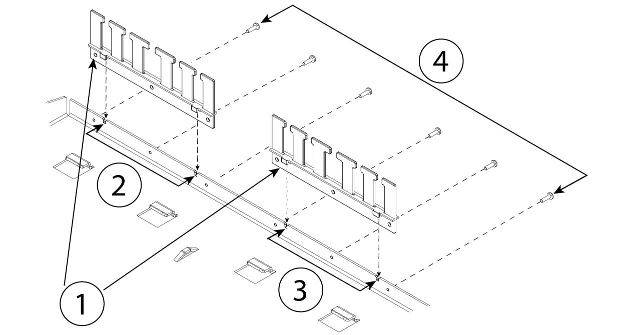
Figure 4. Attach the Cable Guides to the Rack Shelf Flange

1

Two cable guides (part number 700-122664-01)

2

Left cable guide rack shelf cutouts

3

Right cable guide rack shelf cutouts

4

Six of the twelve Phillips M3 x 7-mm screws (part number 48-1921-01)

  1. Align the cable guides with the cutouts on the rack shelf flange (see figure above).

  2. At the rear of the rack shelf, attach the left and right cable guides using six of the twelve Phillips M3 x 7-mm screws (part number 48-1921-01).

    Note


    Drive the screws in while facing the back of the rack shelf.

  3. Set the rack shelf aside. Continue with Step 2 to install the sliding rack tray on the chassis.

    The figure in Step 8 shows the rack shelf with the cable guides attached.

Step 2

Place the chassis with the top facing down on a large, stable work area.

Step 3

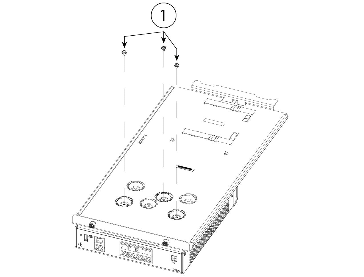
Invert the sliding rack tray and position it on the chassis. You can mount the chassis with the front or rear panel facing front.

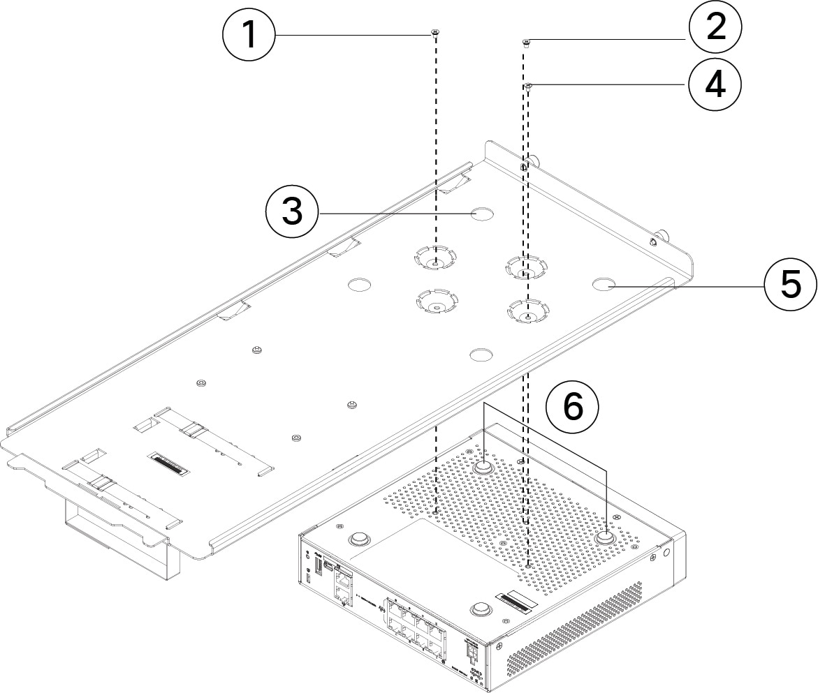
Figure 5. Install the Sliding Rack Tray on the Chassis

1

Three of the twelve M3 x 7-mm screws (part number 48-1921-01)

Step 4

Adjust the position of the chassis and the sliding rack tray until the three mounting holes in the dimples in the bottom of the sliding rack tray are aligned with the mounting holes in the bottom of the chassis.

Step 5

Tighten the three M3 x 7-mm screws to lock the chassis into place on the sliding rack tray (see the figure above).

Step 6

Carefully turn the sliding rack tray right-side up.

Step 7

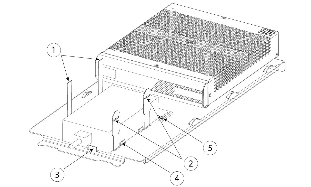
Install the power supply in the sliding rack tray behind the chassis.

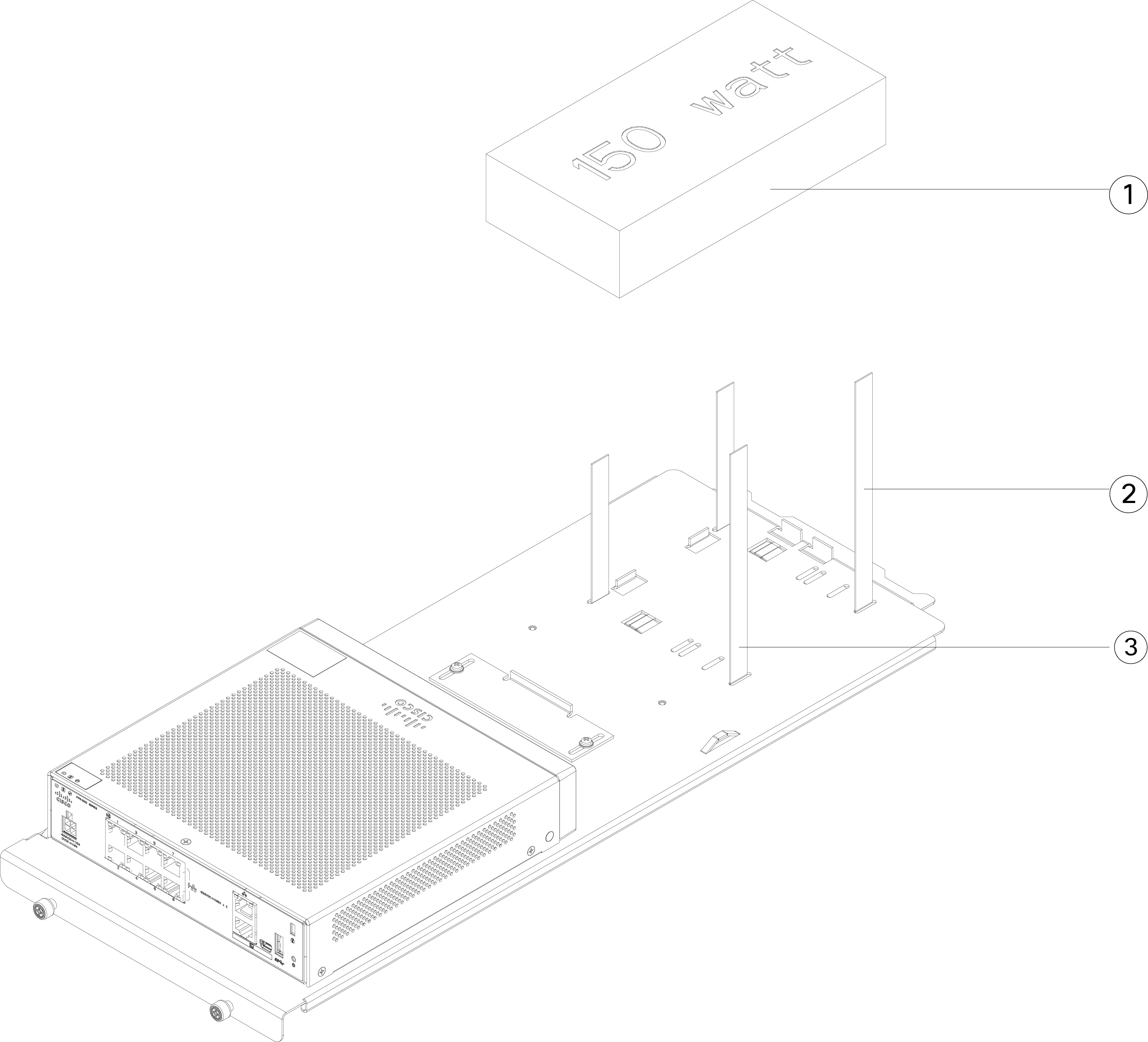
Figure 6. Install the Power Supply in the Sliding Rack Tray

1

Velcro straps for the power supply

2

Velcro straps for the power supply

3

Power supply stop

4

Power supply stop

5

Rear sliding stop and screw (one of two screws on the sliding stop)

  1. Loosen the Velcro straps and place the power supply on the sliding rack tray behind the chassis.

    Make sure the AC inlet cord faces the rear.
  2. Align the power supply to the side and rear stops.

    If the rear sliding stop is not touching the power supply, loosen the two screws, slide the stop up to touch the power supply, and then retighten screws.

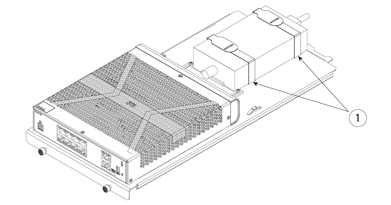
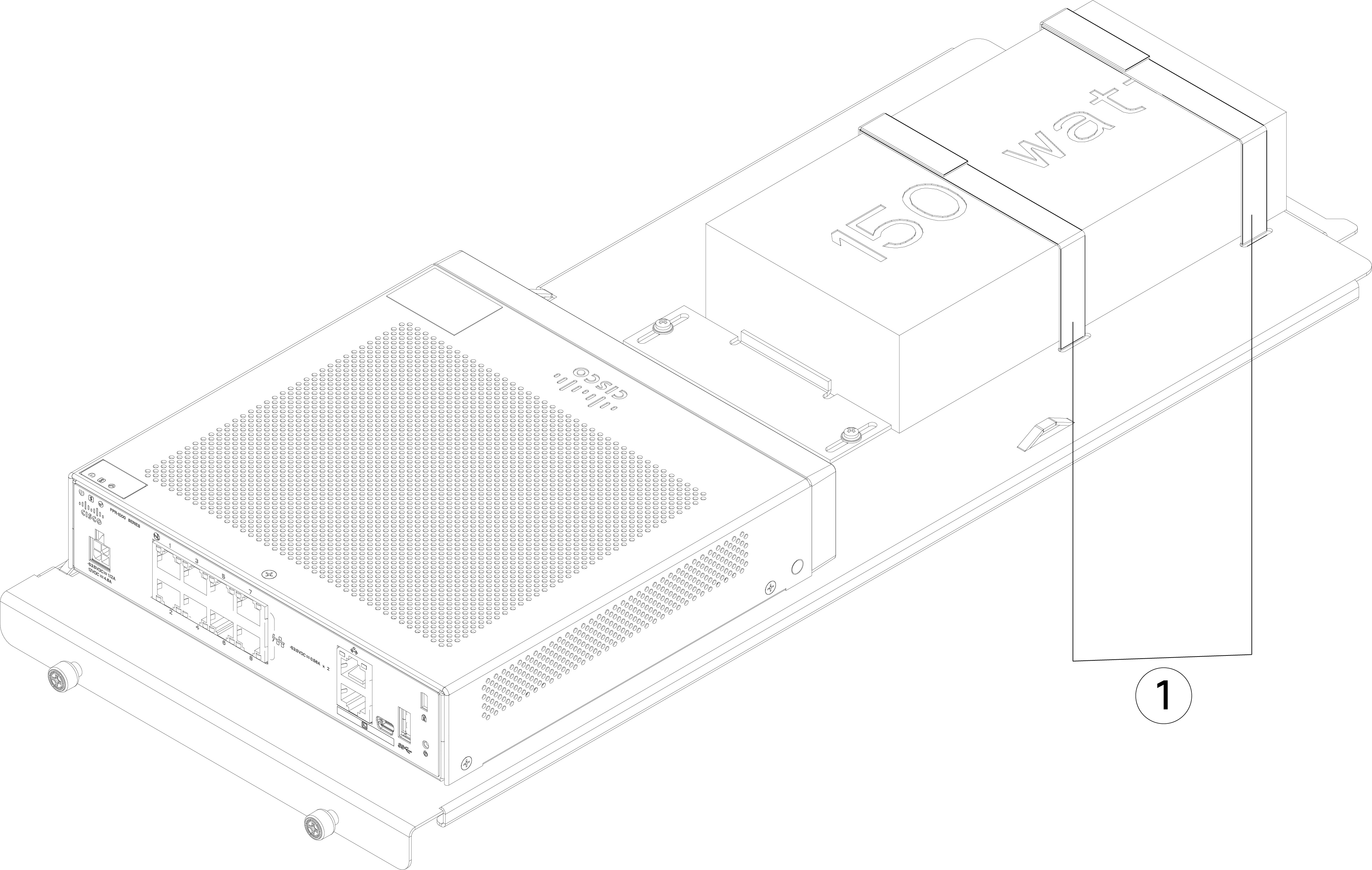
  3. Re-engage the Velcro straps and tighten them to secure the power supply.

    Figure 7. Tighten the Velcro Straps

    1

    Velcro straps tightened over power supply

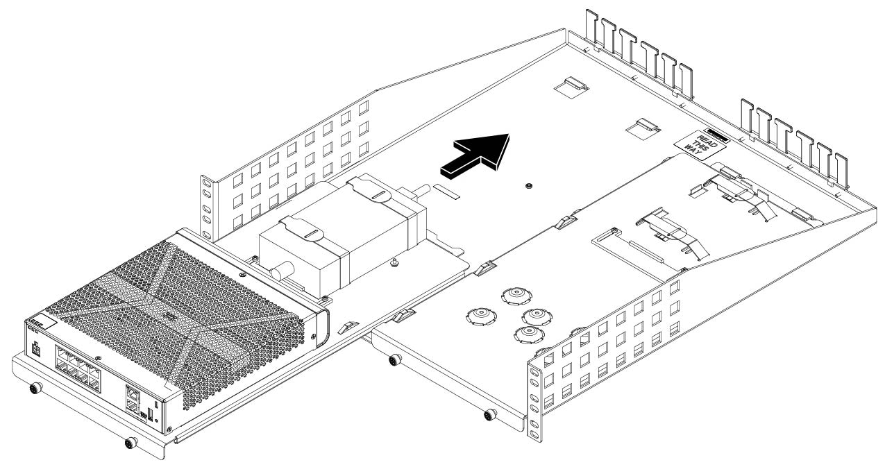
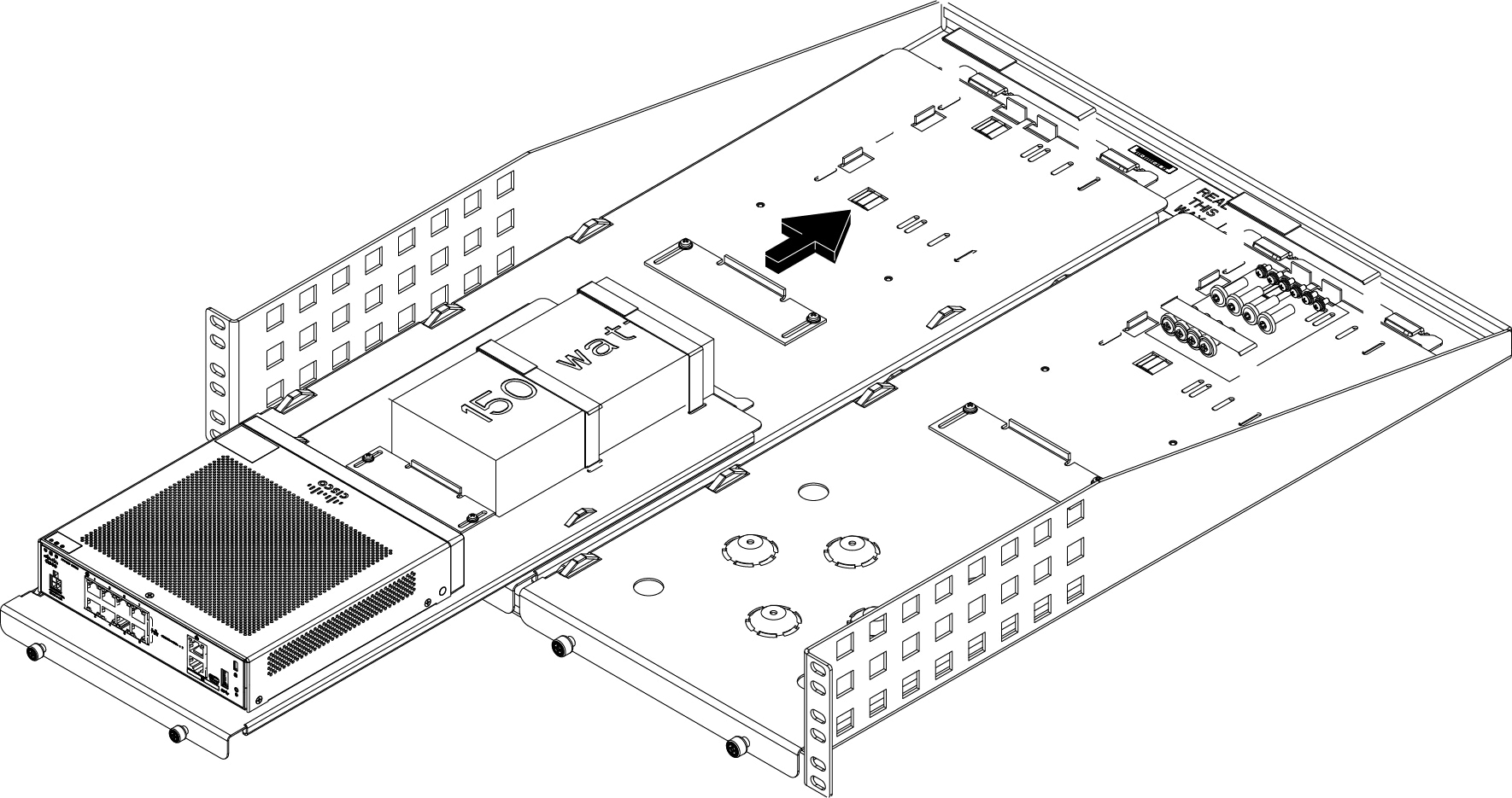
Step 8

Slide the sliding rack tray into the rack shelf.

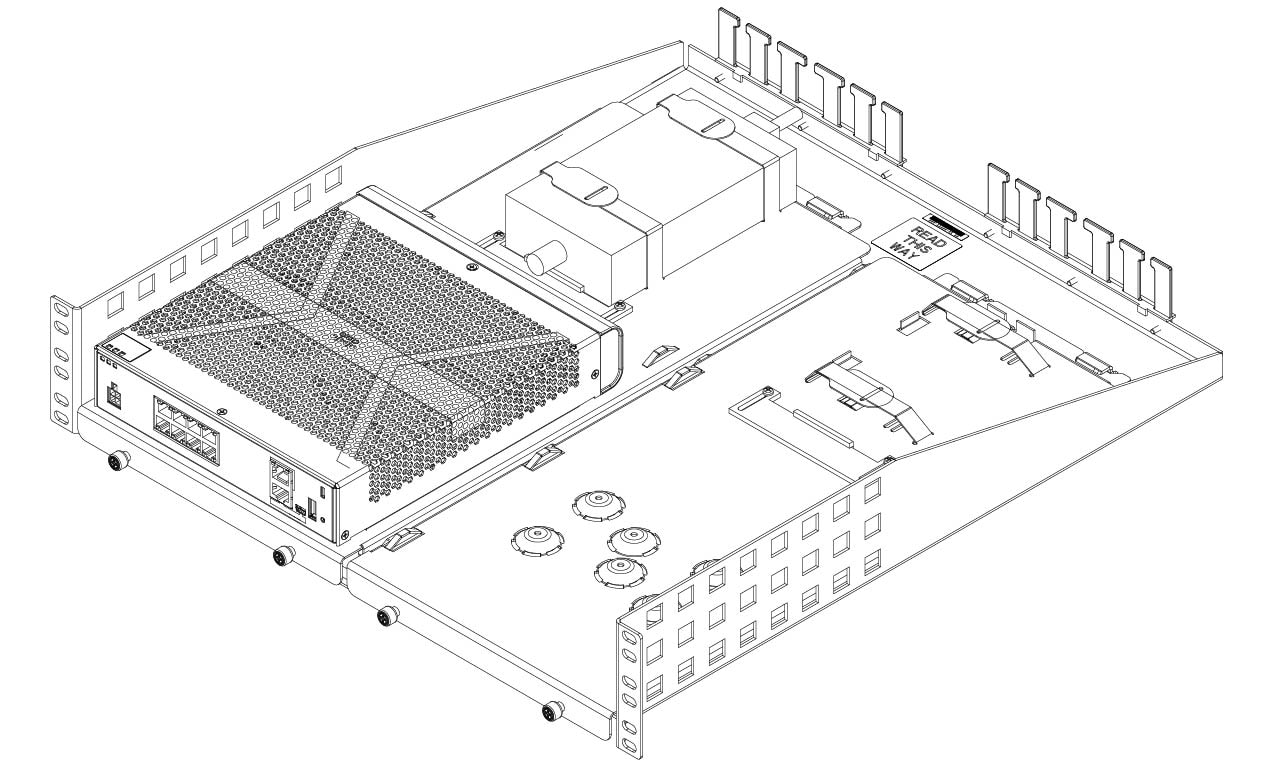
Figure 8. Slide the Sliding Rack Tray Into the Rack Shelf

Step 9

The chassis is now installed in the sliding rack tray, which is installed in the rack shelf. Repeat Steps 1 through 8 to install a second chassis. Use the second sliding rack tray and remaining three M3 x 7-mm screws to install a second chassis to the sliding rack tray and then onto the rack shelf (see Step 3).

Figure 9. Completed Sliding Rack Tray in Rack Shelf Installation

Step 10

Install the rack shelf into your rack using the correct screws (12-24 x 0.75 inch or 10-32 x 0.75 inch) from the rack-mount kit that fit your rack type.

You can now attach your power supply cord and run it through the cable guides.


What to do next

Install the cables according to your default software configuration as described in the Cisco Firepower 1010 Getting Started Guide.