Overview

Features

The Cisco Firepower 1010 and 1010E are a series of compact network security appliances that are supported by Cisco Secure Firewall Threat Defense and Cisco Secure Firewall ASA.
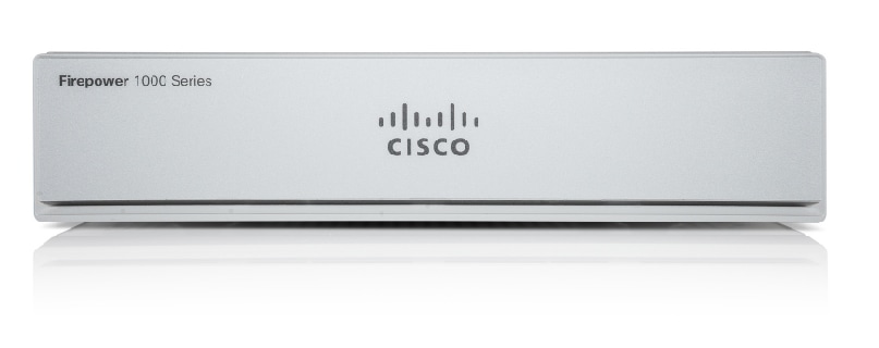
The following figure shows the Cisco Firepower 1010 and 1010E.
Figure 1. Cisco Firepower 1010 and 1010E
Cisco Firepower 1010 and 1010E

The following table lists the features for the Firepower 1010 and 1010E.

Table 1. Firepower 1010 and 1010E features

Feature

1010

1010E

Form factor

Compact, or 2 RU for the rack-mount shelf

Mounting

  • Desktop mount

  • Wall mount

  • Rack mount

Airflow

Side-to-side

No fan

Note


Because the Firepower 1010 and 1010E have no fan, the internal system temperature is significantly higher than the ambient temperature cited in the specifications.

System memory

8-GB

L2 switch

First supported in Firewall Threat Defense Version 6.5 and ASA Version 9.13

Management port

One Gigabit Ethernet RJ-45 10/100/1000 BaseT

Restricted to network management access; connect with an RJ-45 cable

Console port

One RJ-45

Use to access management through an external system

USB Mini B port

One USB Mini B

Use to access management through an external system

USB port

One USB 3.0 Type A

Use to attach an external device such as storage

Network ports

Eight Gigabit Ethernet RJ-45 10/100/1000 BaseT

Each RJ-45 (8P8C) copper port supports auto Medium Dependent Interface Crossover (MDI/X) as well as auto-negotiation for interface speed, duplex, and other negotiated parameters, and are MDI/X-compliant.

The ports are numbered (from top to bottom, left to right) 1, 2, 3, 4, 5, 6, 7, 8. Each port includes a pair of LEDs, one each for connection status and link status. The ports are named and numbered Gigabit Ethernet 1/1 through Gigabit Ethernet 1/8.

Note


You can use ports 7 and 8 as PoE+ ports. PoE+ is first supported in Firewall Threat Defense Version 6.5 and ASA Version 9.13.

Eight Gigabit Ethernet RJ-45 10/100/1000 BaseT

Each RJ-45 (8P8C) copper port supports auto Medium Dependent Interface Crossover (MDI/X) as well as auto-negotiation for interface speed, duplex, and other negotiated parameters, and are MDI/X-compliant.

The ports are numbered (from top to bottom, left to right) 1, 2, 3, 4, 5, 6, 7, 8. Each port includes a pair of LEDs, one each for connection status and link status. The ports are named and numbered Gigabit Ethernet 1/1 through Gigabit Ethernet 1/8.

PoE+ ports

Ports 7 and 8 are PoE+ ports; first supported in Firewall Threat Defense Version 6.5 and ASA Version 9.13.

Note


Not supported

Lock slot

Accepts a standard Kensington T-bar locking mechanism for securing the chassis

Reset button

A small recessed button that if pressed for longer than three seconds resets the chassis to its default state following the next reboot. Configuration variables are reset to factory default, but the flash is not erased and no files are removed.

Power switch

No

System power is controlled by the power cord; there is no power button. To shut down the Firepower 1010 or 1010E, remove the AC power supply.

Power cord socket

The chassis is powered on when you plug in the AC power supply.

AC power supply

One external 150-W AC power supply

There are 150 W of +12 VDC system power.

Note


PoE+ is first supported in Firewall Threat Defense Version 6.5 and ASA Version 9.13.

One external 66-W AC power supply

There are 66 W of +12 VDC system power.

Storage

One 200-GB M.2 SATA SSD drive

The drive is used by the software; there is no user access to the drive.

The drive is not field-replaceable; you must return the chassis to Cisco for drive replacement.

Rubber feet

Four rubber feet on the bottom of the chassis

Note


The rubber feet are needed for proper cooling. Do not remove them.

Package contents

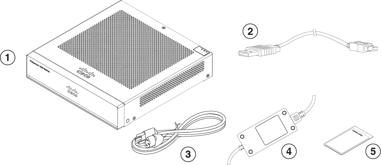
The following figure shows the package contents for the Firepower 1010 and 1010E. Note that the contents are subject to change and your exact contents might contain additional or fewer items.

Figure 2. Firepower 1010 and 1010E package contents
Firepower 1010 and 1010E package contents

1

Chassis

2

USB console cable (Type A to Mini Type B)

Part number 37-1977-01

Optional; in package if ordered

3

Country-specific power cord

Optional; in package if ordered

4

Power supply

5

Cisco Secure Firepower 1010

This document has a URL and QR code that point to the Digital Documentation Portal. The portal contains links to the product information page, the hardware installation guide, the regulatory and safety information guide, the getting started guide, and the zero-touch provisioning guide.

QR code sticker

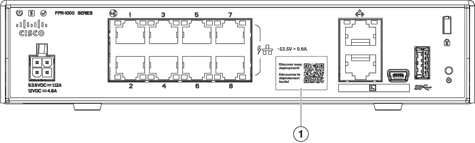
The QR code sticker on the rear panel of the chassis points to the Security Cloud Control document that explains zero-touch provisioning. Zero-touch provisioning allows anyone to connect a new Firepower 1010 to a network so that the IT department can on board the device to Security Cloud Control and configure it remotely. Security Cloud Control supports Firepower Threat Defense version 6.7 and later.

The following figure shows the QR code sticker.

Figure 3. QR code sticker
QR code sticker

The following figure shows the placement of the QR code sticker on the rear panel of the chassis.

Figure 4. Firepower 1010 and 1010E QR code sticker
Firepower 1010 and 1010E QR code sticker

1

QR code sticker

Serial number and compliance label

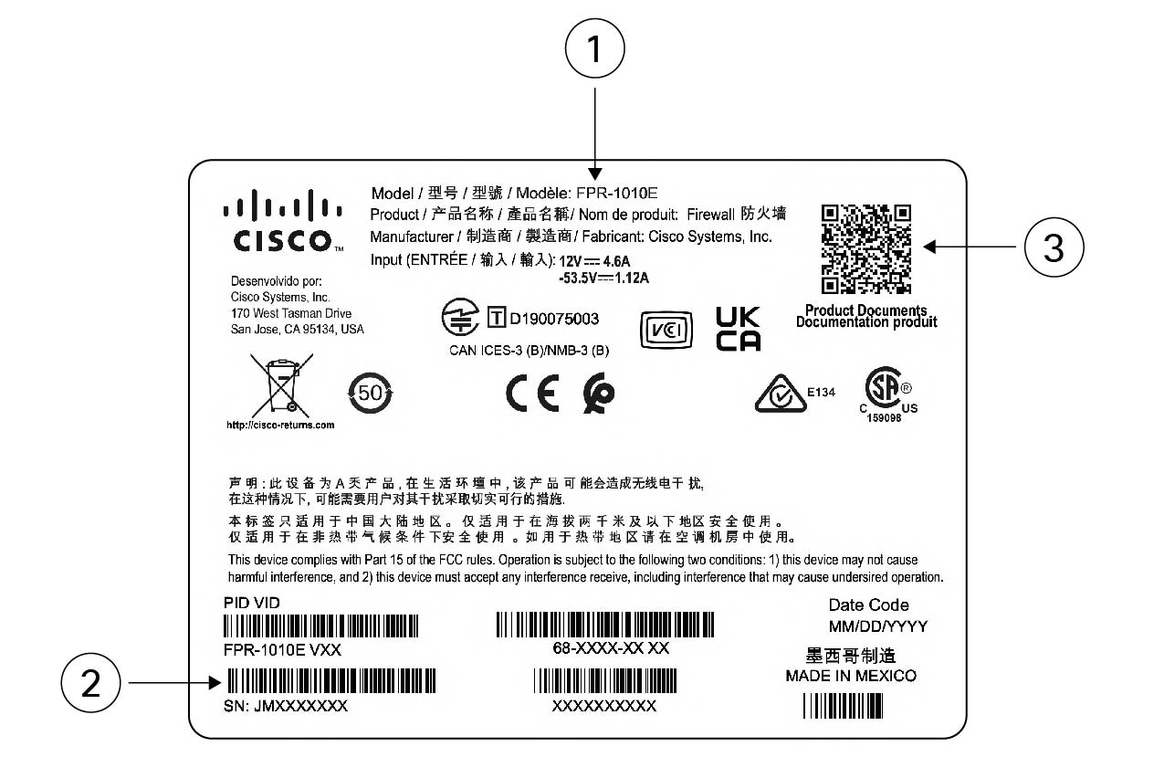
The compliance label on the bottom of the chassis contains the chassis serial number, regulatory compliance marks, and the Digital Documentation Portal QR code that points to the getting started guide, the regulatory and compliance guide, the zero-touch provisioning guide, and the hardware installation guide.

The following figure shows an example compliance label found on the bottom of the chassis.

Figure 5. Compliance label on the chassis
Compliance label on the chassis

1

Chassis model number

2

Chassis serial number

3

Digital Documentation Portal QR code

Front panel

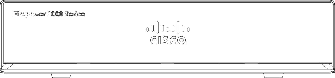
The following figure shows the front panel of the Firepower 1010 and 1010E. Note that there are no connectors or LEDs on the front panel.

Figure 6. Firepower 1010 and 1010E front panel
Firepower 1010 and 1010E front panel

Rear panel

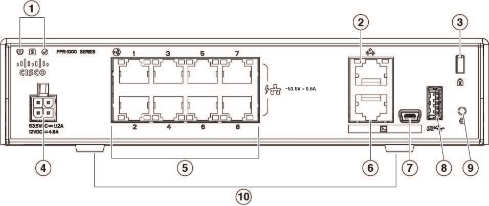
The following figure shows the rear panel of the Firepower 1010 and 1010E. See Status LEDs for a description of the LEDs.

Figure 7. Firepower 1010 and 1010E rear panel
Firepower 1010 and 1010E rear panel

1

Status LEDs

2

Management port

3

USB Type A port

4

Kensington lock slot

5

Power cord socket

6

Network data ports

7

QR code label

8

Console port

9

USB Mini B port

10

Reset button

11

Rubber feet

Status LEDs

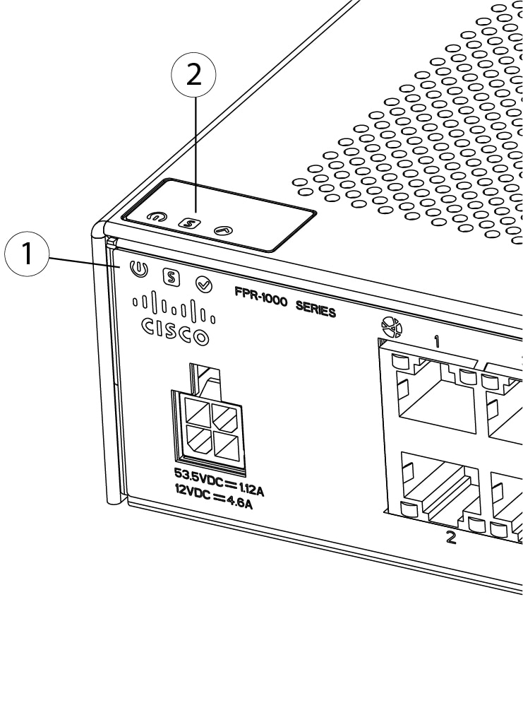
Facing the rear of the chassis, the LEDs are located on the top left edge (facing the front of the chassis, they are in the back right corner of the top). The network port LEDs are at the top sides of each network port.

The following figure shows the status LEDs on the rear panel and on the cover of the chassis.

Figure 8. Status LEDs
Status LEDs

1

Power, Status, and Active LEDs on rear of chassis

2

Power, Status, and Active LEDs on top of chassis

The following figure shows all of the LEDs on the rear panel of the Firepower 1010 and 1010E and describes their states.

Figure 9. Rear panel LEDs
Rear panel LEDs

1

Power

Power supply status:

  • Off —Power supply off.

  • Green—Power supply on.

2

Status

System operating status:

  • Off—System has not booted up yet.

  • Green, flashing quickly—System is booting up.

  • Green—Normal system function.

  • Amber—Critical alarm indicating one or more of the following:

    • Major failure of a hardware or software component.

    • Over-temperature condition.

    • Power voltage outside the tolerance range.

  • Green, flashing slowly (twice in 5 seconds)—Cloud connected.

    Note

     
    Security Cloud Control is valid for threat defense 6.7 and later.
  • Green and amber, flashing—Cloud connection failure.

  • Green—Cloud disconnected.

Note

 
The Security Cloud Control LED pattern applies to zero-touch provisioning. See the Easy Deployment Guide for Cisco Secure Firewall Threat Defense with Cisco Security Cloud Control for more information.

3

Active

Status of the failover pair:

  • Off— Failover is not operational.

  • Green—Failover pair operating normally. The LED is green always unless the chassis in a high availability pair.

  • Amber—When the chassis is in a high availability pair, the LED is amber for the standby unit.

4

Network

Status of the network ports.

Link status (L):

  • Off—No link, or port is not in use.

  • Green—Link established.

  • Green, flashing—Link activity.

5

Network

Status of the network ports.

Connection-speed status (S):

  • Green, flashing—One flash every three seconds = 10 Mbps.

  • Green, flashing—Two rapid flashes = 100 Mbps.

  • Green, flashing—Three rapid flashes = 1000 Mbps.

Hardware specifications

The following table contains hardware specifications for the Firepower 1010 and 1010E.

Table 2. Firepower 1010 and 1010E hardware specifications

1010

1010E

Chassis dimensions (H x W x D)

1.82 x 7.85 x 8.07 inches (4.62 x 19.94 x 20.50 cm)

Rack-mount shelf dimensions (H x W x D)

3.06 x 17.40 x 19.70 inches (7.77 x 44.2 x 50.04 cm) for the 115-W and 66-W power supplies

3.06 x 17.40 x 21.65 inches (7.77 x 44.2 x 54.99 cm) for the 150 -W power supply

Chassis weight

3 lb (1.36 kg)

System power

30 W

Not including any PoE devices connected to the chassis. 55 W is the maximum power for the power supply and 60 W of PoE+ power.

Note


PoE+ is first supported in Firewall Threat Defense Version 6.5 and ASA Version 9.13.

30 W

Temperature

Operating: 32 to 104°F (0 to 40°C)

Derate the maximum operating temperature 1.5° C per 1000 ft above sea level.

Nonoperating: -13 to 158°F (-25 to 70°C) maximum altitude is 40,000 ft

Note


Because the Firepower 1010 and 1010E have no fan, the internal system temperature is significantly higher than the operating temperature.

Humidity

Operating: 90%

Nonoperating: 10 to 90%

Altitude

Operating: 0 to 9843 (3000 m)

Nonoperating: 0 to 15,000 ft (4570 m)

Acoustic noise

0 dBa

Product ID numbers

The following table lists the field-replaceable PIDs associated with the Firepower 1010E and 1010. The spare components are ones that you can order and replace yourself. If any internal components fail, you must get a return material authorization (RMA) for the entire chassis.


Note


See the show inventory command to display a list of the PIDs for your Firepower 1010 and 1010E.


Table 3. Firepower 1010 and 1010E PIDs

PID

Description

FPR1010-ASA-K9

Cisco Firepower 1010 ASA desktop appliance

FPR1010E-ASA-K9

Cisco Firepower 1010E ASA desktop appliance

FPR1010-NGFW-K9

Cisco Firepower 1010 NGFW desktop appliance

FPR1010E-NGFW-K9

Cisco Firepower 1010E NGFW desktop appliance

FPR1K-DT-ACY-KIT

Cisco Firepower 1010 and 1010E accessory kit

PWR-DT-150W-AC

Cisco Firepower 1010 150-W AC power supply

PWR-DT-150W-AC=

Cisco Firepower 1010 150-W AC power supply (spare)

PWR-DT-66WAC

Cisco Firepower 1010E 66-W AC power supply

PWR-DT-66WAC=

Cisco Firepower 1010E 66-W AC power supply (spare)

FPR1K-DT-RACK-MNT=

Cisco Firepower 1010E rack-mount kit to be used with the 66-W AC power supply (spare)

FPR1010-RACK-MNT=

Cisco Firepower 1010 rack-mount kit to be used with the 150-W AC power supply (spare)

FPR1K-DT-WALL-MNT=

Cisco Firepower 1010 and 1010E wall-mount kit (spare)

FPR1K-DT-FIPS-KIT=

Cisco Firepower 1010 FIPS kit (spare)

Power cord specifications

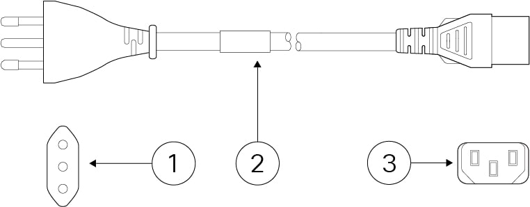
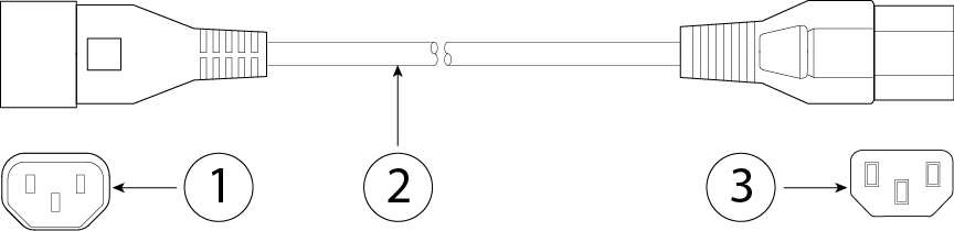
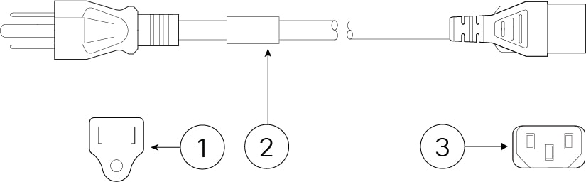
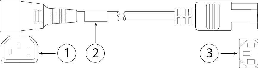
The following C13-type power cords support the 66-W (PWR-DT-66WAC) and 150-W (PWR-DT-150W-AC) power supplies. Each power supply has a separate power cord. Standard power cords or jumper power cords are available for connection to the security appliance. The jumper power cords for use in racks are available as an optional alternative to the standard power cords.

If you do not order the optional power cord with the system, you are responsible for selecting the appropriate power cord for the product. Using a incompatible power cord with this product may result in electrical safety hazard.


Note


Only the approved power cords or jumper power cords provided with the chassis are supported.


The following power cords are supported.

Figure 10. Argentina (CAB-ACR)
Argentina (CAB-ACR)

1

Plug: VA2073

2

Cord set rating: 10 A, 250 V

3

Connector: V1625

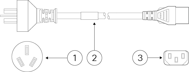
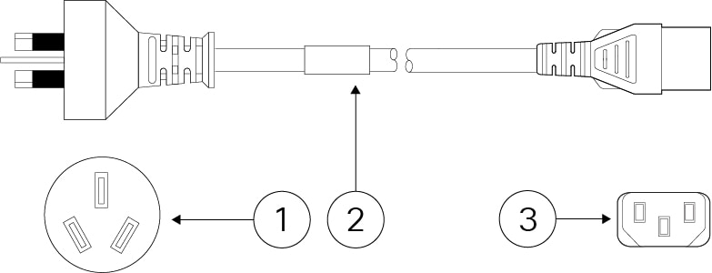
Figure 11. Australia/New Zealand (CAB-ACA)
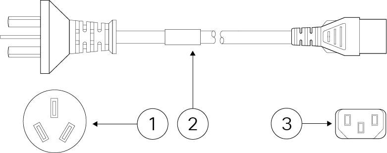
Australia/New Zealand (CAB-ACA)

1

Plug: AU10LS3

2

Cord set rating: 10 A, 250 V

3

Connector: V1625

Figure 12. Brazil (CAB-C13-ACB)
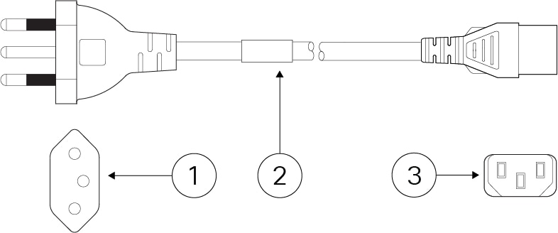
Brazil (CAB-C13-ACB)

1

Plug: NBR 14136

2

Cord set rating: 10 A, 250 V

3

Connector: EL 701B (EN 60320/C13)

Figure 13. China (CAB-ACC)
China (CAB-ACC)

1

Plug: V3203C

2

Cord set rating: 10 A, 250 V

3

Connector: V1625

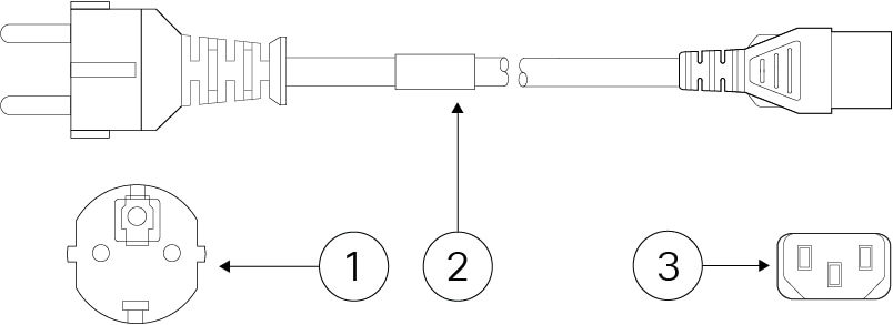
Figure 14. Europe (CAB-ACE)
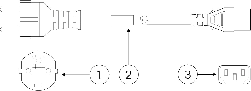
Europe (CAB-ACE)

1

Plug: M2511

2

Cord set rating: 16 A, 250 V

3

Connector: V1625

Figure 15. India (CAB-IND-10A)
India (CAB-IND-10A)

1

Plug: IA16A3-C

2

Cord set rating: 16 A, 250 V

3

Connector: V1625BS-E

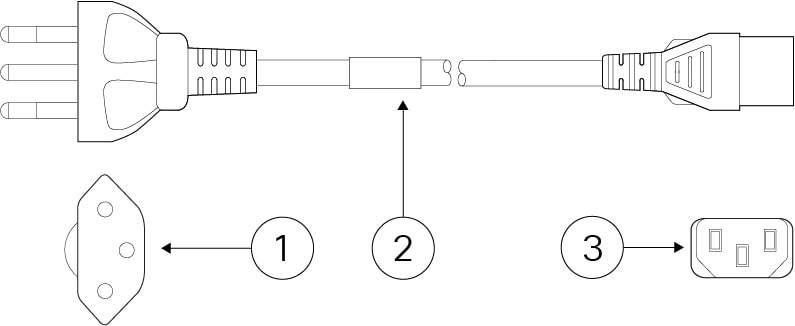
Figure 16. Italy (CAB-ACI)
Italy (CAB-ACI)

1

Plug: IT10S3

2

Cord set rating: 10 A, 250 V

3

Connector: V1625

Figure 17. Japan (CAB-C13-C14-2M-JP) PSE mark
Japan (CAB-C13-C14-2M-JP) PSE Mark

1

IEC 60320-2-2/E

2

Cord set rating: 10 A, 250 V

3

Connector: IEC 60320/C13

Cord length: 2 m

Figure 18. Japan (CAB-JPN-3PIN)
Japan (CAB-JPN-3PIN)

1

Plug: M744

2

Cord set rating: 12 A, 125 V

3

Connector: V1625

Figure 19. Jumper (CAB-C13-C14-2M)
Jumper (CAB-C13-C14-2M)

1

IEC 60320/C14G

2

Cord set rating: 10 A, 250 V

3

Connector: IEC 60320/C13

Cord length: 2.5 m

Figure 20. Korea (CAB-AC-C13-KOR)
Korea (CAB-AC-C13-KOR)

1

Plug: M2511

2

Cord set rating: 10 A, 250 V

3

Connector: V1625

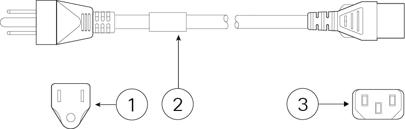
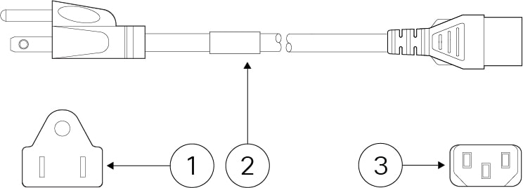
Figure 21. North America (CAB-AC)
North America (CAB-AC)

1

Plug: PS204

2

Cord set rating: 10 A, 250 V

3

Connector: V1625

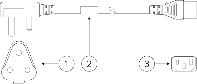
Figure 22. South Africa (AIR-PWR-CORD-SA)
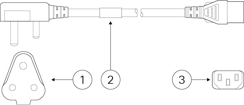
South Africa (AIR-PWR-CORD-SA)

1

Plug: SA16A

2

Cord set rating: 10 A, 250 V

3

Connector: V1625

Figure 23. Switzerland (CAB-ACS)
Switzerland (CAB-ACS)

1

Plug: SW10ZS3

2

Cord set rating: 10 A, 250 V

3

Connector: V1625

Figure 24. Taiwan (CAB-ACTW)
Taiwan (CAB-ACTW)

1

Plug: EL 302 (CNS10917)

2

Cord set rating: 10 A, 125 V

3

Connector: EL 701 (EN 60320/C13)

Figure 25. Taiwan (CAB-AC-TAI)
Taiwan (CAB-AC-TAI)

1

Plug: CNS 10917-2

2

Cord set rating: 10 A, 125 V

3

Connector: IEC 60320/C15

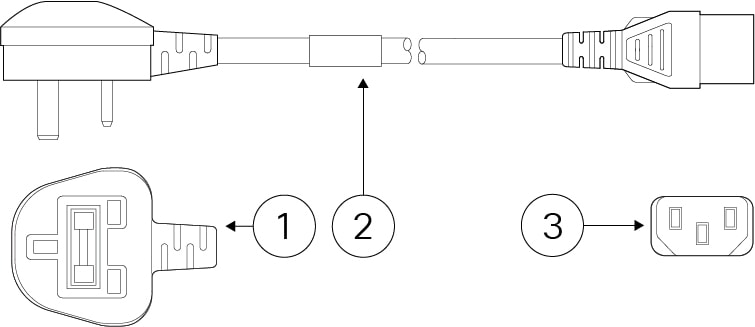
Figure 26. United Kingdom (CAB-ACU)
United Kingdom (CAB-ACU)

1

Plug: 3P BS 1363

2

Cord set rating: 10 A, 250 V

3

Connector: IEC 60320/C13