Before You Start
Deploy and perform initial configuration of the FMC. See the FMC getting started guide.
The documentation set for this product strives to use bias-free language. For the purposes of this documentation set, bias-free is defined as language that does not imply discrimination based on age, disability, gender, racial identity, ethnic identity, sexual orientation, socioeconomic status, and intersectionality. Exceptions may be present in the documentation due to language that is hardcoded in the user interfaces of the product software, language used based on RFP documentation, or language that is used by a referenced third-party product. Learn more about how Cisco is using Inclusive Language.
 Note |
Firepower version 7.0 is the final supported version for the ASA 5508-X and 5516-X. |
Is This Chapter for You?
This chapter explains how to complete the initial configuration of your Firepower Threat Defense (FTD) and how to register the device to a Firepower Management Center (FMC). In a typical deployment on a large network, you install multiple managed devices on network segments. Each device controls, inspects, monitors, and analyzes traffic, and then reports to a managing FMC. The FMC provides a centralized management console with a web interface that you can use to perform administrative, management, analysis, and reporting tasks in service to securing your local network.
For networks that include only a single device or just a few, where you do not need to use a high-powered multiple-device manager like the FMC, you can use the integrated Firepower Device Manager (FDM). Use the FDM web-based device setup wizard to configure the basic features of the software that are most commonly used for small network deployments.
 Note |
The Cisco ASA 5508-X and 5516-X can run either FTD software or ASA software. Switching between FTD and ASA requires you to reimage the device. See Reimage the Cisco ASA or Firepower Threat Defense Device. |
 Note |
Privacy Collection Statement—The ASA 5508-X and 5516-X do not require or actively collect personally-identifiable information. However, you can use personally-identifiable information in the configuration, for example for usernames. In this case, an administrator might be able to see this information when working with the configuration or when using SNMP. |
Deploy and perform initial configuration of the FMC. See the FMC getting started guide.
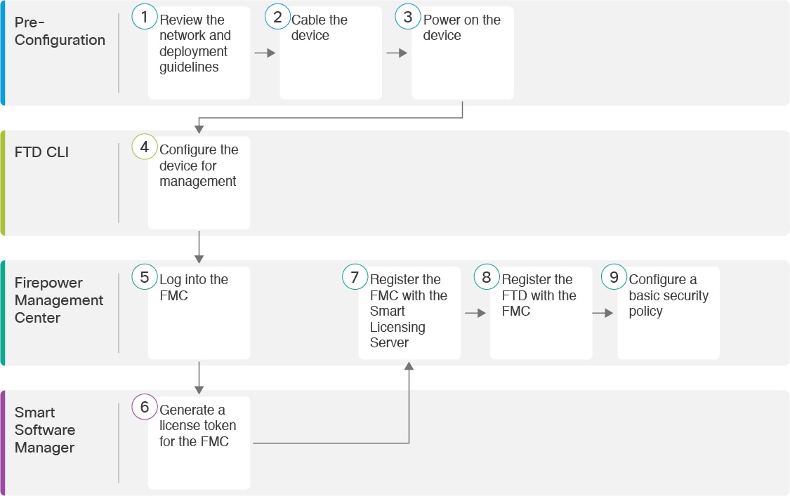
See the following tasks to deploy the FTD with FMC on your chassis.
|
|
Pre-Configuration |
|
|
|
Pre-Configuration |
|
|
|
Pre-Configuration |
|
|
|
FTD CLI |
|
|
|
Firepower Management Center |
|
|
|
Smart Software Manager |
Obtain Licenses for the FMC: Generate a license token for the FMC. |
|
|
Firepower Management Center |
Obtain Licenses for the FMC: Register the FMC with the Smart Licensing server. |
|
|
Firepower Management Center |
|
|
|
Firepower Management Center |
You can manage the FTD using FMC from the Management 1/1 interface, or in 6.7 and later, a data interface. By default, the Management 1/1 interface is enabled and configured as a DHCP client. You can configure the Management interface and an FMC access data interface during initial setup at the console port. You can configure other data interfaces after you connect the FTD to the FMC.
 Note |
FMC access from a data interface has the following limitations:
|
 Note |
In 6.5 and earlier, the Management interface is configured with an IP address (192.168.45.45). |
See the following sample network deployments for ideas on how to place your FTD device in your network.
Both the FMC and FTD require internet access from management for licensing and updates.
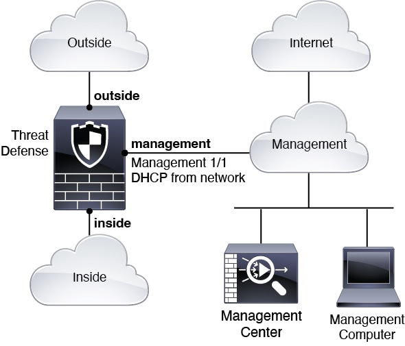
The following figure shows a possible network deployment for the ASA 5508-X or 5516-X where the FMC and management computer connect to the management network. The management network has a path to the internet for licensing and updates.
 Note |
For a remote branch setup, we recommend that you use the standalone document specific to that deployment. |
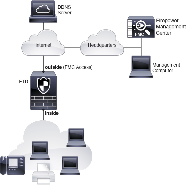
The following figure shows the recommended network deployment for the ASA 5508-X or 5516-X using the outside interface for management. This scenario is ideal for managing branch offices from a central headquarters. You can perform initial setup of the FTD at headquarters and then send a pre-configured device to a branch location.
Either the FTD or FMC needs a public IP address or hostname. If the FTD receives a public IP address using DHCP, then you can optionally configure Dynamic DNS (DDNS) for the outside interface. DDNS ensures the FMC can reach the FTD at its Fully-Qualified Domain Name (FQDN) if the FTD's IP address changes. If the FTD receives a private IP address, then the FMC needs to have a public IP address or hostname.
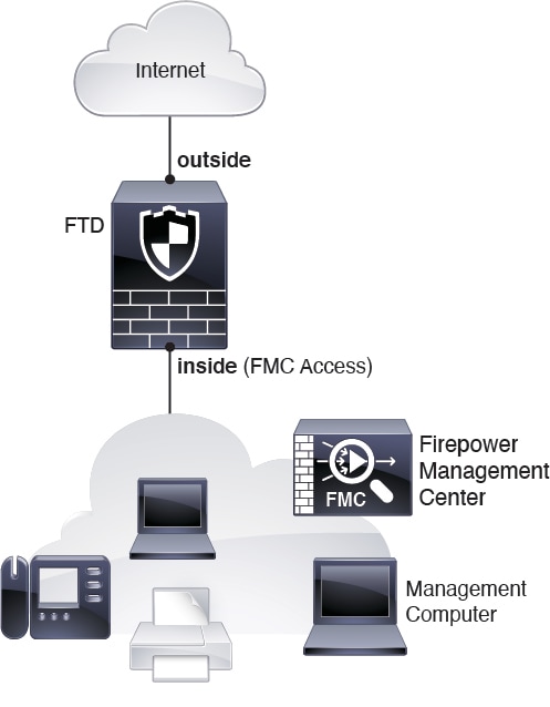
The following figure shows the recommended network deployment for the ASA 5508-X or 5516-X using the inside interface for management.
The FMC can only communicate with the FTD on the management interface in 6.6 and earlier. Moreover, both the FMC and FTD require internet access from management for licensing and updates.
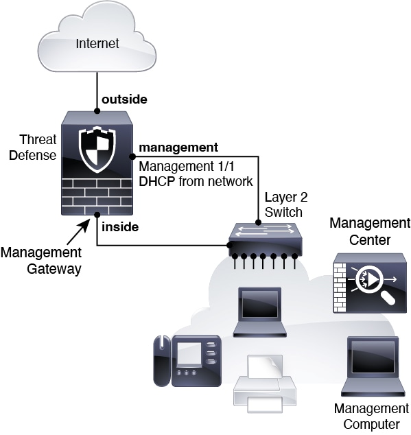
The following figure shows a possible network deployment for the ASA 5508-X or 5516-X where the ASA acts as the internet gateway for the FMC and FTD managamement.You can also use this scenario in 6.7 and later for a High Availability deployment, for example.
In the following diagram, the ASA 5508-X or 5516-X acts as the internet gateway for the management interface and the FMC by connecting Management 1/1 to an inside interface through a Layer 2 switch, and by connecting the FMC and management computer to the switch. (This direct connection is allowed because the management interface is separate from the other interfaces on the FTD.)
To cable one of the above scenarios on the ASA 5508-X or 5516-X, see the following steps.
 Note |
Other topologies can be used, and your deployment will vary depending on your basic logical network connectivity, ports, addressing, and configuration requirements. |
| Step 1 |
Cable for a separate management network. 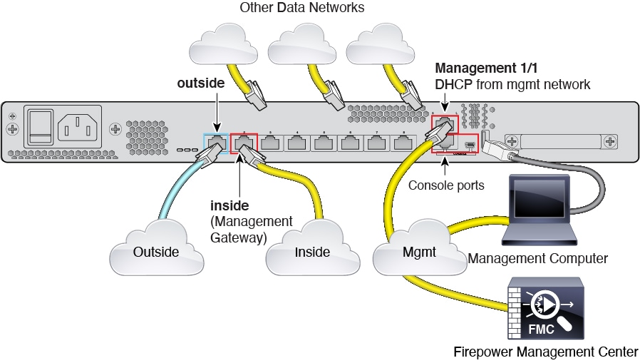
|
||
| Step 2 |
(6.7 and later) Cable for a remote management deployment: 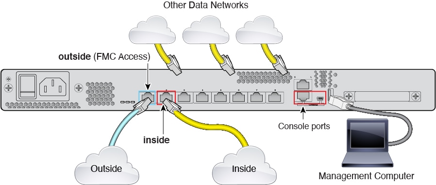
The FMC and your management computer reside at a remote headquarters, and can reach the FTD over the internet. |
||
| Step 3 |
(6.7 and later) Cable for an inside management deployment: 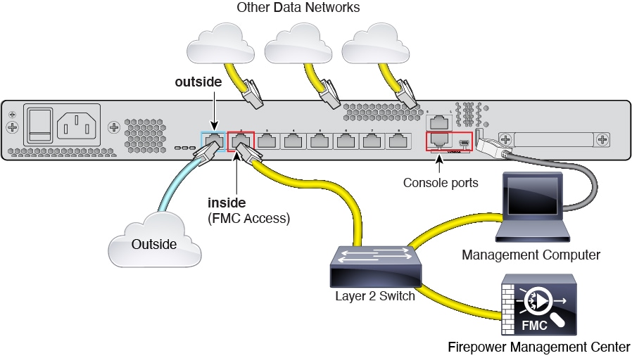
The FMC and your management computer reside on the inside network with your other inside end points. |
||
| Step 4 |
(6.6 and earlier) Cable for an edge deployment. 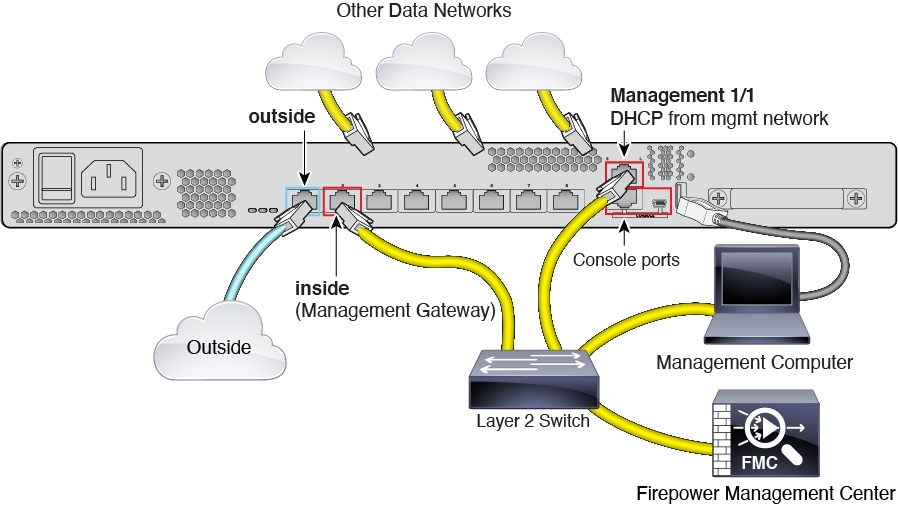
|
System power is controlled by a rocker power switch located on the rear of the device.
It's important that you provide reliable power for your device (for example, using an uninterruptable power supply (UPS)). Loss of power without first shutting down can cause serious file system damage. There are many processes running in the background all the time, and losing power does not allow the graceful shutdown of your system.
| Step 1 |
Attach the power cord to the device, and connect it to an electrical outlet. |
| Step 2 |
Turn the power on using the standard rocker-type power on/off switch located on the rear of the chassis, adjacent to the power cord. |
| Step 3 |
Check the Power LED on the front or rear of the device; if it is solid green, the device is powered on. 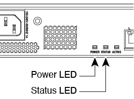

|
| Step 4 |
Check the Status LED on the front or rear of the device; after it is solid green, the system has passed power-on diagnostics. |
Connect to the FTD CLI to perform initial setup, including setting the Management IP address, gateway, and other basic networking settings using the setup wizard. The dedicated Management interface is a special interface with its own network settings. In 6.7 and later: If you do not want to use the Management interface for FMC access, you can use the CLI to configure a data interface instead. You will also configure FMC communication settings.
| Step 1 |
Connect to the FTD CLI, either from the console port or using SSH to the Management interface, which obtains an IP address from a DHCP server by default. If you intend to change the network settings, we recommend using the console port so you do not get disconnected. |
||||
| Step 2 |
Log in with the username admin and the password Admin123.
|
||||
| Step 3 |
The first time you log in to FTD, you are prompted to accept the End User License Agreement (EULA) and to change the admin password. You are then presented with the CLI setup script.
Defaults or previously entered values appear in brackets. To accept previously entered values, press Enter.
See the following guidelines:
Example: |
||||
| Step 4 |
Identify the FMC that will manage this FTD. configure manager add {hostname | IPv4_address | IPv6_address | DONTRESOLVE} reg_key [nat_id]
Example:If the FMC is behind a NAT device, enter a unique NAT ID along with the registration key, and specify DONTRESOLVE instead of the hostname, for example: Example:If the FTD is behind a NAT device, enter a unique NAT ID along with the FMC IP address or hostname, for example: Example: |
||||
| Step 5 |
(Optional) (6.7 and Later) Configure a data interface for FMC access. configure network management-data-interface You are then prompted to configure basic network settings for the data interface.
See the following details for using this command:
Example:Example: |
||||
| Step 6 |
(Optional) (6.7 and Later) Limit data interface access to an FMC on a specific network. configure network management-data-interface client ip_address netmask By default, all networks are allowed. |
Register your device to a FMC.
Use the FMC to configure and monitor the FTD.
For information on supported browsers, refer to the release notes for the version you are using (see https://www.cisco.com/go/firepower-notes).
| Step 1 |
Using a supported browser, enter the following URL. https://fmc_ip_address |
| Step 2 |
Enter your username and password. |
| Step 3 |
Click Log In. |
All licenses are supplied to the FTD by the FMC. You can purchase the following licenses:
Threat—Security Intelligence and Next-Generation IPS
Malware—Malware
URL—URL Filtering
RA VPN—AnyConnect Plus, AnyConnect Apex, or AnyConnect VPN Only
For a more detailed overview on Cisco Licensing, go to cisco.com/go/licensingguide
Have a master account on the Smart Software Manager.
If you do not yet have an account, click the link to set up a new account. The Smart Software Manager lets you create a master account for your organization.
Your Smart Software Licensing account must qualify for the Strong Encryption (3DES/AES) license to use some features (enabled using the export-compliance flag).
| Step 1 |
Make sure your Smart Licensing account contains the available licenses you need. When you bought your device from Cisco or a reseller, your licenses should have been linked to your Smart Software License account. However, if you need to add licenses yourself, use the Find Products and Solutions search field on the Cisco Commerce Workspace. Search for the following license PIDs: 
|
||
| Step 2 |
If you have not already done so, register the FMC with the Smart Licensing server. Registering requires you to generate a registration token in the Smart Software Manager. See the FMC configuration guide for detailed instructions. |
Register the FTD to the FMC.
Gather the following information that you set in the FTD initial configuration:
The FTD management IP address or hostname, and NAT ID
The FMC registration key
| Step 1 |
In the FMC, choose . |
| Step 2 |
From the Add drop-down list, choose Add Device. 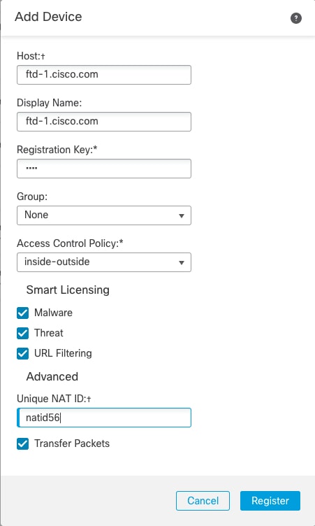 Set the following parameters:
|
| Step 3 |
Click Register, and confirm a successful registration. If the registration succeeds, the device is added to the list. If it fails, you will see an error message. If the FTD fails to register, check the following items:
For more troubleshooting information, see https://cisco.com/go/fmc-reg-error. |
This section describes how to configure a basic security policy with the following settings:
Inside and outside interfaces—Assign a static IP address to the inside interface, and use DHCP for the outside interface.
DHCP server—Use a DHCP server on the inside interface for clients.
Default route—Add a default route through the outside interface.
NAT—Use interface PAT on the outside interface.
Access control—Allow traffic from inside to outside.
To configure a basic security policy, complete the following tasks.
|
|
|
|
|
|
|
|
|
|
|
|
|
|
|
|
|
Enable FTD interfaces, assign them to security zones, and set the IP addresses. Typically, you must configure at least a minimum of two interfaces to have a system that passes meaningful traffic. Normally, you would have an outside interface that faces the upstream router or internet, and one or more inside interfaces for your organization’s networks. Some of these interfaces might be “demilitarized zones” (DMZs), where you place publically-accessible assets such as your web server.
A typical edge-routing situation is to obtain the outside interface address through DHCP from your ISP, while you define static addresses on the inside interfaces.
The following example configures a routed mode inside interface with a static address and a routed mode outside interface using DHCP.
| Step 1 |
Choose , and click the Edit ( |
||
| Step 2 |
Click Interfaces.  |
||
| Step 3 |
Click Edit ( The General tab appears. 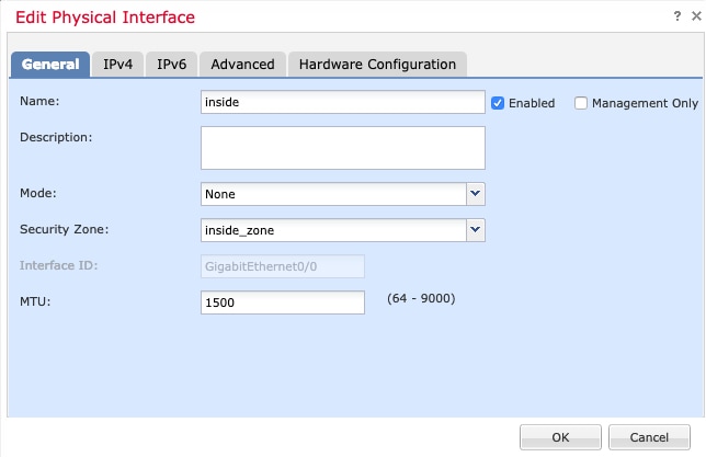 |
||
| Step 4 |
Click the Edit ( The General tab appears. 
|
||
| Step 5 |
Click Save. |
Enable the DHCP server if you want clients to use DHCP to obtain IP addresses from the FTD.
| Step 1 |
Choose , and click the Edit ( |
| Step 2 |
Choose . |
| Step 3 |
On the Server page, click Add, and configure the following options: 
|
| Step 4 |
Click OK. |
| Step 5 |
Click Save. |
The default route normally points to the upstream router reachable from the outside interface. If you use DHCP for the outside interface, your device might have already received a default route. If you need to manually add the route, complete this procedure. If you received a default route from the DHCP server, it will show in the IPv4 Routes or IPv6 Routes table on the page.
| Step 1 |
Choose , and click the Edit ( |
| Step 2 |
Choose , click Add Route, and set the following: 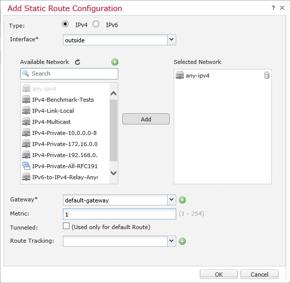
|
| Step 3 |
Click OK. The route is added to the static route table.  |
| Step 4 |
Click Save. |
A typical NAT rule converts internal addresses to a port on the outside interface IP address. This type of NAT rule is called interface Port Address Translation (PAT).
| Step 1 |
Choose , and click . |
||
| Step 2 |
Name the policy, select the device(s) that you want to use the policy, and click Save. 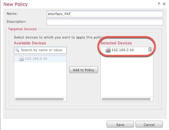 The policy is added the FMC. You still have to add rules to the policy. |
||
| Step 3 |
Click Add Rule. The Add NAT Rule dialog box appears. |
||
| Step 4 |
Configure the basic rule options: 
|
||
| Step 5 |
On the Interface Objects page, add the outside zone from the Available Interface Objects area to the Destination Interface Objects area. 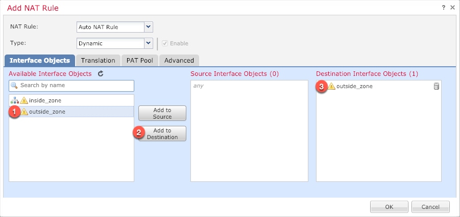 |
||
| Step 6 |
On the Translation page, configure the following options: 
|
||
| Step 7 |
Click Save to add the rule. The rule is saved to the Rules table.  |
||
| Step 8 |
Click Save on the NAT page to save your changes. |
If you created a basic Block all traffic access control policy when you registered the FTD with the FMC, then you need to add rules to the policy to allow traffic through the device. The following procedure adds a rule to allow traffic from the inside zone to the outside zone. If you have other zones, be sure to add rules allowing traffic to the appropriate networks.
See the FMC configuration guide to configure more advanced security settings and rules.
| Step 1 |
Choose , and click the Edit ( |
| Step 2 |
Click Add Rule, and set the following parameters: 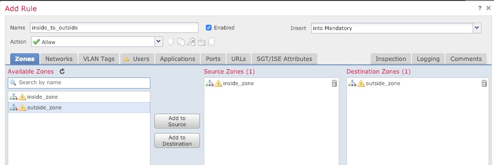
Leave the other settings as is. |
| Step 3 |
Click Add. The rule is added to the Rules table.  |
| Step 4 |
Click Save. |
Deploy the configuration changes to the FTD; none of your changes are active on the device until you deploy them.
| Step 1 |
Click Deploy in the upper right.  |
| Step 2 |
Select the device in the Deploy Policies dialog box, then click Deploy.  |
| Step 3 |
Ensure that the deployment succeeds. Click the icon to the right of the Deploy button in the menu bar to see status for deployments. 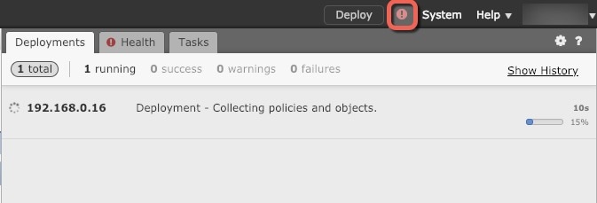 |
Use the command-line interface (CLI) to set up the system and do basic system troubleshooting. You cannot configure policies through a CLI session. You can access the CLI by connecting to the console port.
You can SSH to the management interface of the FTD device. You can also connect to the address on a data interface if you open the interface for SSH connections. SSH access to data interfaces is disabled by default.
| Step 1 |
To log into the CLI, connect your management computer to the console port.. The ASA 5508-X and 5516-X ship with a USB A-to-B serial cable. Be sure to install any necessary USB serial drivers for your operating system (see the hardware guide). Use the following serial settings:
|
| Step 2 |
Log in to the FTD CLI using the admin username and the password you set at initial setup (the default is Admin123). After logging in, for information on the commands available in the CLI, enter help or ? . For usage information, see the Cisco Firepower Threat Defense Command Reference. |
It's important that you shut down your system properly. Simply unplugging the power or pressing the power switch can cause serious file system damage. Remember that there are many processes running in the background all the time, and unplugging or shutting off the power does not allow the graceful shutdown of your Firepower system.
| Step 1 |
Connect to the console port to access the FTD CLI, and then shut down the FTD. shutdown Example: |
| Step 2 |
After the FTD shuts down, and the console shows that "It is safe to power off now", you can then turn off the power switch and unplug the power to physically remove power from the chassis if necessary. Alternatively, you can reboot the system by typing y at the prompt. |
To continue configuring your FTD, see the documents available for your software version at Navigating the Cisco Firepower Documentation.
For information related to using FMC, see the Firepower Management Center Configuration Guide.