Deploy the Threat Defense Virtual on OCI

You can deploy the threat defense virtual on the Oracle Cloud Infrastructure (OCI), a public cloud computing service that enables you to run your applications in a highly-available, hosted environment offered by Oracle.

The following procedures describe how to prepare your OCI environment and launch the threat defense virtual instance. You log into the OCI portal, search the OCI Marketplace for the Cisco Firepower NGFW virtual firewall (NGFWv) offering, and launch the compute instance. After launching the threat defense virtual, you must configure route tables to direct traffic to the firewall depending on the traffic’s source and destination.

Overview

The Cisco Secure Firewall Threat Defense Virtual runs the same software as physical Cisco threat defense to deliver proven security functionality in a virtual form factor. The threat defense virtual can be deployed in the public OCI. It can then be configured to protect virtual and physical data center workloads that expand, contract, or shift their location over time.

OCI Compute Shapes

A shape is a template that determines the number of CPUs, amount of memory, and other resources that are allocated to an instance. The threat defense virtual support the following OCI shape types:

Table 1. Supported Compute Shapes for Threat Defense Virtual

OCI Shape

Supported Threat Defense Virtual version

Attributes

Interfaces

oCPUs

RAM (GB)

Intel VM.Standard2.4

7.1, 7.2.x, and 7.3.x

4

60

Minimum 4, Maximum 4

Intel VM.Standard2.8

7.1, 7.2.x, and 7.3.x

8

120

Minimum 4, Maximum 8

  • *SR-IOV mode is supported with Flex shapes from Version 7.4.x and later.

  • In OCI, 1 oCPU is equal to 2 vCPU.

  • The threat defense virtual requires a minimum of 4 interfaces.

You create an account on OCI, launch a compute instance using the Cisco Firepower NGFW virtual firewall (NGFWv) offering on the Oracle Cloud Marketplace, and choose an OCI shape.

End-to-End Procedure

The following flowchart illustrates the workflow for deploying Threat Defense Virtual on Oracle Cloud Infrastructure.

Workspace

Steps

Oracle Cloud Infrastructure

Deploy the Threat Defense virtual on OCI: Configure the Virtual Cloud Network (VCN) (Networking > Virtual Cloud Networks > CIDR block > Create VCN.

Oracle Cloud Infrastructure

Deploy the Threat Defense virtual on OCI: Create the Network Security Group. (Networking > Virtual Cloud Networks > Virtual Cloud Network Details > Network Security Groups > Create Network Security Group.

Oracle Cloud Infrastructure

Deploy the Threat Defense Virtual on OCI: Create the Internet Gateway. Networking > Virtual Cloud Networks > Virtual Cloud Network Details > Internet Gateways > Create Internet Gateway.

Oracle Cloud Infrastructure

Deploy the Threat Defense Virtual on OCI: Create the Subnet. Networking > Virtual Cloud Networks > Virtual Cloud Network Details > Subnets > Create Subnet.

Oracle Cloud Infrastructure

Deploy the Threat Defense Virtual on OCI: Search for “Cisco Secure Firewall” in the OCI Marketplace.

Oracle Cloud Infrastructure

Deploy the Threat Defense Virtual on OCI: Launch and set up the threat defense virtual instance.

Oracle Cloud Infrastructure

Deploy the Threat Defense Virtual on OCI: Provide the Day-0 configuration.

Oracle Cloud Infrastructure

Deploy the Threat Defense Virtual on OCI: Deploy the threat defense virtual on OCI using setup wizard.

Oracle Cloud Infrastructure

Deploy the Threat Defense Virtual on OCI: Attach the Interfaces.Compute > Instances > Instance Details > Attached VNICs.

Management Center

Manage the threat defense virtual by using the Management Center

Prerequisites

  • Create an OCI account at https://www.oracle.com/cloud/.

  • A Cisco Smart Account. You can create one at Cisco Software Central (https://software.cisco.com/).

  • License the threat defense virtual.

    • Configure all license entitlements for the security services from the management center.

    • See “Licensing” in the Cisco Secure Firewall Management Center Admin Guide for more information about how to manage licenses.

  • Interface requirements:

    • Management interfaces (2) — One used to connect the threat defense virtual to the management center, second used for diagnostics; cannot be used for through traffic.

    • Traffic interfaces (2) — Used to connect the threat defense virtual to inside hosts and to the public network.

  • Communications paths:

    • Public IPs for access into the threat defense virtual.

  • For threat defense virtual system requirements, see Cisco Secure Firewall Threat Defense Compatibility Guide.

Guidelines and Limitations

Supported Features

  • Deployment in the OCI Virtual Cloud Network (VCN)

  • Routed mode (default)

  • Licensing – Only BYOL is supported

  • Management Center support only.

  • Single Root I/O Virtualization (SR-IOV) is supported.

Performance Tiers for FTDv Smart Licensing

The threat defense virtual supports performance-tiered licensing that provides different throughput levels and VPN connection limits based on deployment requirements.

Table 2. Threat Defense Virtual Licensed Feature Limits Based on Entitlement

Performance Tier

Device Specifications (Core/RAM)

Rate Limit

RA VPN Session Limit

FTDv5, 100Mbps

4 core/8 GB

100Mbps

50

FTDv10, 1Gbps

4 core/8 GB

1Gbps

250

FTDv20, 3Gbps

4 core/8 GB

3Gbps

250

FTDv30, 5Gbps

8 core/16 GB

5Gbps

250

FTDv50, 10Gbps

12 core/24 GB

10Gbps

750

FTDv100, 16Gbps

16 core/32 GB

16Gbps

10,000

See the "Licensing" chapter in the Cisco Secure Firewall Management Center Admin Guide for guidelines when licensing your threat defense virtual device.


Note


To change the vCPU/memory values, you must first power off the threat defense virtual device.


Performance Optimizations

To achieve the best performance out of the threat defense virtual, you can make adjustments to the both the VM and the host. See Virtualization Tuning and Optimization on OCI for more information.

Receive Side Scaling—The threat defense virtual supports Receive Side Scaling (RSS), which is a technology utilized by network adapters to distribute network receive traffic to multiple processor cores. Supported on Version 7.0 and later. See Multiple RX Queues for Receive Side Scaling (RSS) for more information.

Snort

  • If you are observing abnormal behavior such as Snort taking a long time to shut down, or the VM being slow in general or when a certain process is executed, collect logs from the threat defense virtual and the VM host. Collection of overall CPU usage, memory, I/O usage, and read/write speed logs will help troubleshoot the issues.

  • High CPU and I/O usage is observed when Snort is shutting down. If a number of threat defense virtual instances have been created on a single host with insufficient memory and no dedicated CPU, Snort will take a long time to shut down which will result in the creation of Snort cores.

Unsupported Features

  • Local management support via device manager.

  • Threat Defense Virtual native HA

  • Autoscale on version 7.0 and earlier.

  • Transparent/inline/passive modes

  • Data Interface configuration via DHCP

  • IPv6

Limitations

  • Threat Defense Virtual deployment on OCI does not support Mellanox 5 as vNICs in the SR-IOV mode.

  • Separate routing rules required for Firewall Threat Defense Virtual for both static and DHCP configuration.

Sample Network Topology

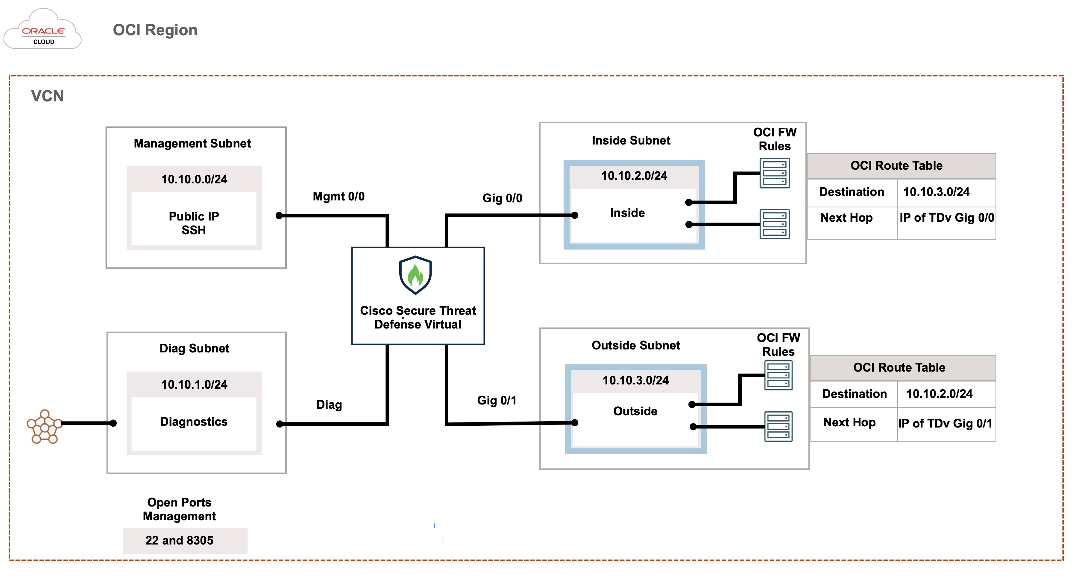
The following figure shows the recommended topology for the threat defense virtual in Routed Firewall Mode with 4 subnets configured in OCI for the threat defense virtual (management, diagnostic, inside, and outside).

Figure 1. Sample Threat Defense Virtual on OCI Deployment with subnets in four VCNs
Figure 2. Sample Threat Defense Virtual on OCI Deployment with four subnets in a VCN

Note


When you are using four subnets in a single VCN, the routes specific to a subnet must be added to the route table associated with the subnet.


How to Manage Secure Firewall Threat Defense Virtual Device

You have two options to manage your Secure Firewall Threat Defense Virtual.

Secure Firewall Management Center

If you are managing large numbers of devices, or if you want to use the more complex features and configurations that the threat defense allows, use the management center to configure your devices instead of the integrated device manager.


Important


You cannot use both the device manager and the management center to manage the threat defense device. Once the device manager integrated management is enabled, it won't be possible to use the management center to manage the threat defense device, unless you disable the local management and re-configure the management to use the management center. On the other hand, when you register the threat defense device to the management center, the device manager onboard management service is disabled.


Caution


Currently, Cisco does not have an option to migrate your device manager configuration to the management center and vice-versa. Take this into consideration when you choose what type of management you configure for the threat defense device.


Secure Firewall device manager

The device manager is an onboard integrated manager.

The device manager is a web-based configuration interface included on some of the threat defense devices. The device manager lets you configure the basic features of the software that are most commonly used for small networks. It is especially designed for networks that include a single device or just a few, where you do not want to use a high-powered multiple-device manager to control a large network containing many of the threat defense devices.


Note


See the Cisco Secure Firewall Device Manager Configuration Guide for list of the threat defense devices that support the device manager.


Configure OCI Environment

You can configure the Virtual Cloud Network (VCN) for your threat defense virtual deployment as follows:

  • Multiple VCNs - At a minimum, you need four VCNs, one for each interface of the threat defense virtual. This allows for isolated traffic inspection between different networks.

  • Single VCN with Subnets - Alternatively, you can configure a single VCN with four subnets, one for each interface of the threat defense virtual. In this configuration, traffic between subnets within the same VCN can be inspected and controlled by the firewall using associated route tables. This allows you to manage inter-subnet traffic effectively while using a single VCN.

You can continue with the following procedures to complete the Management VCN. Then you return to Networking to create VCNs for the diagnostic, inside, and outside interfaces.

Procedure


Step 1

Log into OCI and choose your region.

OCI is divided into multiple regions that are isolated from each other. The region is displayed in the upper right corner of your screen. Resources in one region do not appear in another region. Check periodically to make sure you are in the intended region.

Step 2

Choose Networking > Virtual Cloud Networks and click Create VCN.

Step 3

Enter a descriptive Name for your VCN, for example, FTDv-Management.

Step 4

Enter a CIDR block for your VCN.

  1. An IPv4 CIDR block of IP addresses. CIDR (Classless Inter-Domain Routing) notation is a compact representation of an IP address and its associated routing prefix. For example, 10.0.0.0/24.

    Note


    Use DNS hostnames in this VCN.

Step 5

Click Create VCN.


What to do next

Continue with the following procedures to complete the Management VCN. When you complete the management VCN you'll create VCNs for the diagnostic, inside, and outside interfaces.


Note


After you select a service from the navigation menu, the menu on the left includes the compartments list. Compartments help you organize resources to make it easier to control access to them. Your root compartment is created for you by Oracle when your tenancy is provisioned. An administrator can create more compartments in the root compartment and then add the access rules to control which users can see and take action in them. See the Oracle document Managing Compartments for more information.


Create the Network Security Group

A network security group consists of a set of vNICs and a set of security rules that apply to those vNICs.

Procedure


Step 1

Choose Networking > Virtual Cloud Networks > Virtual Cloud Network Details > Network Security Groups, and click Create Network Security Group.

Step 2

Enter a descriptive Name for your Network Security Group, for example, FTDv-Mgmt-Allow-22-8305.

Step 3

Click Next.

Step 4

Add your security rules:

  1. Add a rule to allow TCP port 22 for SSH access.

  2. Add a rule to allow TCP port 8305 for HTTPS access.

    The threat defense virtual can be managed via the management center, which requires port 8305 to be opened for HTTPS connections.

Note


You apply these security rules to the management interface/VCN.

Step 5

Click Create.


Create the Internet Gateway

An Internet gateway is required to make your management subnet publicly accessible.

Procedure


Step 1

Choose Networking > Virtual Cloud Networks > Virtual Cloud Network Details > Internet Gateways, and click Create Internet Gateway.

Step 2

Enter a descriptive Name for your Internet gateway, for example, FTDv-IG.

Step 3

Click Create Internet Gateway.

Step 4

Add the route to the Internet Gateway:

  1. Choose Networking > Virtual Cloud Networks > Virtual Cloud Network Details > Route Tables.

  2. Click on the link for your default route table to add route rules.

  3. Click Add Route Rules.

  4. From the Target Type drop-down, select Internet Gateway.

  5. Enter the Destination IPv4 CIDR Block, for example 0.0.0.0/0.

  6. From the Target Internet Gateway drop-down, select the gateway you created.

  7. Click Add Route Rules.


Create the Subnet

Each VCN will have one subnet, at a minimum. You’ll create a Management subnet for the Management VCN. You’ll also need a Diagnostic subnet for the Diagnostic VCN, need an Inside subnet for the Inside VCN, and an Outside subnet for the Outside VCN.

If you are using one VCN, then you will create Management subnet, Diagnostic subnet, Inside subnet, and Outside subnet within the VCN.

Procedure


Step 1

Choose Networking > Virtual Cloud Networks > Virtual Cloud Network Details > Subnets, and click Create Subnet.

Step 2

Enter a descriptive Name for your subnet, for example Management.

Step 3

Select a Subnet Type (leave the recommended default of Regional).

Step 4

Enter a CIDR Block, for example, 10.10.0.0/24. The internal (non-public) IP address for the subnet is taken from this CIDR block.

Step 5

Select one of the route tables you created previously from the Route Table drop-down.

Step 6

Select the Subnet Access for your subnet.

For the Management subnet, this must be Public Subnet.

Step 7

Select the DHCP Option.

Step 8

Select a Security List that you created previously.

Step 9

Click Create Subnet.


What to do next

After you configure your VCNs (Management, Diagnostic, Inside, Outside), you are ready to launch the threat defense virtual. See the following figure for an example of the threat defense virtual VCN configuration.

Figure 3. threat defense virtual Virtual Cloud Networks

Deploy the Threat Defense Virtual on OCI

Deploy the threat defense virtual on OCI via a Compute instance using the Cisco Firepower NGFW virtual firewall (NGFWv) offering on the Oracle Cloud Marketplace. Select the most appropriate machine shape based on characteristics such as the number of CPUs, amount of memory, and network resources.

Procedure


Step 1

Log into the OCI portal.

The region is displayed in the upper right corner of your screen. Make sure you are in the intended region.

Step 2

Choose Marketplace > Applications.

Step 3

Search Marketplace for “Cisco Firepower NGFW virtual firewall (NGFWv)” and choose the offering.

Step 4

Review the Terms and Conditions, and check the I have reviewed and accept the Oracle Terms of Use and the Partner terms and conditions.check box.

Step 5

Click Launch Instance.

Step 6

Enter a descriptive Name for your instance, for example FTDv-6-7.

Step 7

Click Change Shape and select the shape with the number of CPUs, amount of RAM, and number of interfaces required for the threat defense virtual, for example VM.Standard2.4 (see Overview).

Step 8

From the Virtual Cloud Network drop-down, choose the Management VCN.

Step 9

From the Subnet drop-down, choose the Management subnet if it's not autopopulated.

Step 10

Check Use Network Security Groups to Control Traffic and choose the security group you configured for the Management VCN.

Step 11

Click the Assign a Public Ip Address radio button.

Step 12

Under Add SSH keys, click the Paste Public Keys radio button and paste the SSH key.

Linux-based instances use an SSH key pair instead of a password to authenticate remote users. A key pair consists of a private key and public key. You keep the private key on your computer and provide the public key when you create an instance. See Managing Key Pairs on Linux Instances for guidelines.

Step 13

Click the Show Advanced Options link to expand the options.

Step 14

Under Initialization Script, click the Paste Cloud-Init Script radio button to provide the day0 configuration for your threat defense virtual. The day0 configuration is applied during the firstboot of the threat defense virtual.

The following example shows a sample day0 configuration you can copy and paste in the Cloud-Init Script field:

{
"Hostname": "ftdv-oci",
"AdminPassword": "myPassword@123456",
"FirewallMode": "routed",
"IPv4Mode": "dhcp",
"ManageLocally":"No",
"FmcIp": "1.2.3.4",
"FmcRegKey": "cisco123reg",
"FmcNatId": "cisco123nat"
}
  • FmcRegKey ― This is a one-time-use registration key used to register registering the device to a management center. The registration key is any user-defined alphanumeric value up to 37 characters in length.

  • FmcNatId ― This is a unique one-time-use string (user-defined). If the device and the management center are separated by a NAT device, you must enter a unique NAT ID, along with the unique registration key.

Step 15

Click Create.


What to do next

Monitor the threat defense virtual instance, which shows the state as Provisioning after you click the Create button.


Important


It’s important to monitor the status. As soon as the threat defense virtual instance goes from Provisioning to Running state, you need to attach the VNICs as required before the threat defense virtual boot completes.


Attach the Interfaces

The threat defense virtual enters the Running state with one VNIC attached (see Compute > Instances > Instance Details > Attached VNICs). This is referred to as the Primary VNIC, and maps to the Management VCN. Before the threat defense virtual completes the first boot, you need to attach the VNICs for the other VCN subnets you created previously (diagnostic, inside, outside) so that the VNICs are correctly detected on the threat defense virtual.

Procedure


Step 1

Select your newly launched threat defense virtual instance.

Step 2

Choose Attached VNICs > Create VNIC.

Step 3

Enter a descriptive Name for your VNIC, for example, Inside.

Step 4

Select the VCN from the Virtual Cloud Network drop-down.

Step 5

Select your subnet from the Subnet drop-down.

Step 6

Check Use Network Security Groups to Control Traffic and choose the security group you configured for the selected VCN.

Step 7

Check Skip Source Destination Check Network Security Groups to Control Traffic.

Step 8

(Optional) Specify a Private IP Address. This is only required if you want to choose a particular IP for the VNIC.

If you do not specify an IP, OCI will assign an IP address from the CIDR block you assigned to the subnet.

Step 9

Click Save Changes to create the VNIC.

Step 10

Repeat this procedure for each VNIC your deployment requires.


Add Route Rules for the Attached VNICs

Add route table rules to the diagnostic, inside, and outside route tables.

Procedure


Step 1

Choose Networking > Virtual Cloud Networks and click the default route table associated with the VCN (inside or outside).

Step 2

Click Add Route Rules.

Step 3

From the Target Type drop-down, select Private IP.

Step 4

From the Destination Type drop-down, select CIDR Block.

Step 5

Enter the Destination CIDR Block, for example 0.0.0.0/0.

Step 6

Enter the private IP address of the VNIC in the Target Selection field.

If you did not explicitly assign an IP address to the VNIC, you can find the auto-assigned IP address from the VNIC details (Compute > Instances > Instance Details > Attached VNICs).

Step 7

Click Add Route Rules.

Step 8

Repeat this procedure for each VNIC your deployment requires.


Deploy Auto Scale Solution

The following sections describe how the components of the Auto Scale solution work for the threat defense virtual on OCI.

Auto Scale Use Case

The use case for the threat defense virtual Auto Scale on OCI solution is shown in the following figure. Internet-facing Load Balancer will have a public IP address with ports enabled using Listener and Target Group combination.

Port-based bifurcation is possible for traffic, and it can be achieved via NAT rules. This is explained in the following sections.

Figure 4. Secure Firewall Threat Defense Virtual Auto Scale Use Case Diagram

Scope

This document covers the detailed procedures to deploy the threat defense virtual Auto Scale for OCI solution.


Important


  • Read the entire document before you begin your deployment.

  • Make sure the prerequisites are met before you start deployment.

  • Make sure you follow the steps and order of execution as described herein.


Prerequisites

Permission and Policies

Following are the OCI permissions and policies that you require to implement the solution:

  1. Users and Group


    Note


    You must be an OCI User or a Tenancy Administrator to create the Users and Groups.

    Create Oracle Cloud Infrastructure user accounts and a group to which the user accounts belong. If the relevant group with user accounts exist, you need not create them. For instructions on creating users and groups, see Creating Groups and Users.

  2. Group Policies

    You need to create the policies and then map them to the group. To create the policies, go to OCI > Identity & Security > Policies > Create Policy. Create and add the following policies to the desired group:

    • Allow group <Group_Name> to use metrics in compartment <Compartment_Name>

    • Allow group <Group_Name> to manage alarms in compartment <Compartment_Name>

    • Allow group <Group_Name> to manage ons-topics in compartment <Compartment_Name>

    • Allow group <Group_Name> to inspect metrics in compartment <Compartment_Name>

    • Allow group <Group_Name> to read metrics in compartment <Compartment_Name>

    • Allow group <Group_Name> to use tag-namespaces in compartment <Compartment_Name>

    • Allow group <Group_Name> to read log-groups in compartment <Compartment_Name>

    • Allow group <Group_Name> to use instance-pools compartment <Compartment_Name>

    • Allow group <Group_Name> to use cloud-shell in tenancy

    • Allow group <Group_Name> to read objectstorage-namespace in tenancy

    • Allow group <Group_Name> to manage repos in tenancy


    Note


    You can create policies at tenancy level as well. It is at your discretion how you want to provide all the permissions.


  3. Permission for Oracle Functions

    To enable a Oracle-Function to access another Oracle Cloud Infrastructure resource, include the function in a dynamic group, and then create a policy to grant the dynamic group access to that resource.

  4. Create Dynamic Group

    To create dynamic groups, go to OCI > Identity & Security > Dynamic Group > Create Dynamic Group

    Specify the following rule while creating the dynamic group:

    ALL {resource.type = 'fnfunc', resource.compartment.id = '<Your_Compartment_OCID>'}

    For more details on dynamic groups, see:

  5. Create Policy for Dynamic Group

    To add policy, go to OCI > Identity & Security > Policies > Create Policy. Add the following policy to the group:

    Allow dynamic-group <Dynamic_Group_Name> to manage all-resources in compartment <Compartment_OCID>

Download files from GitHub

FTDv – OCI Autoscale solution is delivered as a GitHub repository. You can pull or download the files from the repository.

Python3 Environment

A make.py file can be found in the cloned repository. This program compresses the oracle functions and template files into a Zip file; copy them to a target folder. In order to do these tasks, the Python 3 environment should be configured.


Note


This python script can be used only on Linux environment.


Infrastructure Configuration

The following must be configured:

  1. VCN

    Create VCN as required for your FTDv application. Create VCN with the Internet Gateway having at least one of the subnet attached with route to internet.

    For information on creating VCN, see https://docs.oracle.com/en-us/iaas/Content/GSG/Tasks/creatingnetwork.htm.

  2. Application Subnets

    Create subnets as required for your FTDv application. To implement the solution as per this use case, FTDv instance requires 4 subnets for its operation.

    For information on creating subnet, see https://docs.oracle.com/en-us/iaas/Content/Network/Tasks/managingVCNs_topic-Overview_of_VCNs_and_Subnets.htm#.

  3. Outside Subnet

    Subnet should have route with '0.0.0.0/0' to Internet Gateway. This subnet contains the Outside interface of Cisco FTDv and the Internet-facing Load balancer. Ensure that the NAT Gateway is added for outbound traffic.

    For more information, see the following documents:

  4. Inside Subnet

    This is similar to the Application Subnets, with or without NAT/Internet gateway.


    Note


    For FTDv health probes, you can reach the metadata server (169.254.169.254) through Port 80.


  5. Management Subnet

    Management subnet should be public so that it supports SSH accessibility to the FTDv.

  6. Security Groups- Network Security Group for FTDv Instance

    Configure the security group for FTDv instances that allows the Oracle Functions(in same VCN) perform SSH connections to FTDv's management address.

  7. Object Storage Namespace

    This object storage namespace is used for hosting static website, having configuration.txt file. You must create a pre-authenticated requests for the configuration.txt file. This pre-authenticated URL is used during the template deployment.


    Note


    Ensure that the following configurations that are uploaded are accessible by the FTDv instances through HTTP URL.

    When FTDv is booted, it executes the following command$ copy /noconfirm <configuration.txt file’s pre-authenticated request URL > disk0:Connfiguration.txt

    This command enables FTDv launch to be configured with configuration.txt file.


Secure Firewall Management Center Prerequisites

You can manage the threat defense virtual devices using the Secure Firewall Management Center, a full-featured, multidevice manager. The threat defense virtual registers and communicates with the FMC on the Management interface that you allocated to the threat defense virtual virtual machine.

Create the objects required for threat defense virtual configuration and management, including a device group to deploy policies and install updates on multiple devices. All the configurations applied on the device group is pushed to the threat defense virtual instances.

The following sections provide a brief overview of basic steps to prepare the management center. For complete information on the procedure, refer Secure Firewall Management Center Configuration Guide. When you prepare the management center, make sure you record the following information:

  • Secure Firewall Management Center Public IP Address

  • Username and Password (If memory based scaling is enabled, you have to provide 2 user credentials)

  • Security Zone Names

  • Secure Firewall Management Center Access policy Name

  • Secure Firewall Management Center NAT Policy Name

  • Device Group Name

Create User in Secure Firewall Management Center

Create a new user in Secure Firewall Management Center with Admin privileges to be used only by Autoscale Manager.


Note


You must have an Secure Firewall Management Center user account dedicated to the threat defense virtual Autoscale solution to prevent conflicts with other FMC sessions.


Procedure

Create new user in Secure Firewall Management Center with Admin privileges. Choose System > Users and click Create User. The username must be Linux-valid:

  • Maximum 32 alphanumeric characters, plus hyphen (-) and underscore (_)

  • All lowercase

  • Should not start with hyphen (-); must have alphabets; should not include a period (.), at sign (@), or slash (/)

Complete user options as required for your environment. See the Secure Firewall Management Center Configuration Guide for complete information.


Create Device Group

Device groups enable you to easily assign policies and install updates on multiple devices. A device group should be created and rules should be applied on it. All the configurations applied on the device group are pushed to threat defense virtual instances.

Procedure

Step 1

Choose Devices > Device Management.

Step 2

From the Add drop-down menu select Add Group.

Step 3

Enter the Device group name.

Step 4

Click Ok to create the device group.


Create Network and Host Objects

Create the following objects to be used for threat defense virtual configuration.

Procedure

Step 1

Create Host with its name as oci-metadata-server and its IP as 169.254.169.254.

Step 2

Create a port with its name as health-check-port and its value as 8080 or any other port as required.

Step 3

Create Inside interface, choose Interface > Security Zone. Select type as Routed. Provide a name for the interface, example, inside-sz.

Step 4

Create Outside interface, choose Interface > Security Zone. Select type as Routed. Provide a name for the interface, example, outside-sz.


Create NAT Policy

Create a NAT policy and create the necessary NAT rules to forward traffic from the outside interface to your application, and attach this policy to the device group you created for Autoscale.

Procedure

Step 1

Choose Devices > NAT

Step 2

From the New Policy drop-down list, choose Threat Defense NAT.

Step 3

Enter a unique Name.

Step 4

Optionally, enter a Description.

Step 5

Configure NAT rules. Refer Configure NAT for Threat Defense in the Secure Firewall Management Center Device Configuration Guide for guidelines on how to create NAT rules and apply NAT policies. The following figure shows a basic approach in setting the rules.

Figure 5. NAT Rules

Step 6

Click Save.


Create NAT Rules

A typical NAT rule converts internal addresses to a port on the outside interface IP address. This type of NAT rule is called interface Port Address Translation (PAT). See Configure NAT for Threat Defense in the Secure Firewall Management Center Device Configuration Guide for more information.

Configure the following 2 mandatory rules that are required in your NAT policy:

Procedure

Step 1

Configure the following NAT Rule for Inbound health check:

  • Source Zone : Outside Zone

  • Destination Zone : Inside Zone

  • Original-sources : any-ipv4

  • Original Destinations: Source Interface IP

  • Original source port: Default

  • Original-destination-port: health-check-port

  • Translated-sources: Destination Interface IP

  • Translated-destination: oci-metadata-server

  • Translated source port: default

  • Translated-destination-port: HTTP

The following figure shows the NAT rule for inbound health check.

Figure 6. Inbound health NAT rule

Step 2

Configure the following NAT rule for outbound health check.

  • Source Zone : Inside Zone

  • Destination Zone : Outside Zone

  • Original-sources : any-ipv4

  • Original Destinations: Source Interface IP

  • Original source port: Default

  • Original-destination-port: health-check-port

  • Translated-sources: Destination Interface IP

  • Translated-destination: oci-metadata-server

  • Translated source port: default

  • Translated-destination-port: HTTP

The following figure shows the NAT rule for outbound health check.

Figure 7. Outbound health check NAT rule

Similarly, any NAT rules can be added for data traffic, and this configuration pushes them to threat defense virtual devices.


Create an Access Policy

Configure access control to allow traffic from inside to outside. An Access Policy with all required policies can be created, health port object should be allowed such that traffic on this port is allowed to reach the device. Within an access control policy, access control rules provide a granular method of handling network traffic across multiple managed devices. Proper configuration and sequencing of the rules are essential to build an effective deployment. See the Best Practices for Access Control Rules in the Secure Firewall Management Center Device Configuration Guide.

Assign the device group (created as part of pre-requisites) to the access policy using Policy Assignments.

Procedure

Step 1

Choose Policies > Access Control.

Step 2

Click New Policy.

Step 3

Enter a unique Name and, optionally, a Description.

Step 4

Configure security settings and rules for your deployment. For more information, see Access Control in the Secure Firewall Management Center Device Configuration Guide.


Encrypt Password


Note


For more information on this procedure, see Create Vaults and Secrets.


Password for FTDv is used to configure all the FTDv instances being used while autoscaling and it is used to create connections for Rest APIs calls for several configuration purpose.

Therefore, you need to save and process the password every now and then. Owing to the frequent changes and vulnerability, editing or saving the password in the plain-text format is not allowed. Password must be in an encrypted format only.

To obtain password in encrypted form:

Procedure


Step 1

Create Vault.

OCI Vault provides services to create and save master encryption keys safely, and methods for encryption and decryption in using them. So Vault should be created (if not having already) in the same compartment as the rest of the autoscale solution.

Go to OCI > Identity & Security > Vault > Choose or Create New Vault

.

Step 2

Create Master Encryption Key.

One master encryption key is needed to encrypt the plain text password.

Go to OCI > Identity & Security > Vault > Choose or Create Key

Choose any of the keys from any of the given algorithm with any bit of length.

  1. AES – 128, 192, 256

  2. RSA – 2048, 3072, 4096

  3. ECDSA – 256, 384, 521

Figure 8. Create Key

Step 3

Create encrypted password.

  1. Go to OCI > Open CloudShell (OCI Cloud Terminal)

  2. Execute following command by replacing <Password> as your password.

    echo -n '<Password>' | base64
  3. From the selected Vault, copy cryptographic endpoint and master encryption key OCID. Replace the following values, and then execute the encrypt command:

    • KEY_OCID with Your key’s OCID

    • Cryptographic_Endpoint_URL with Your vault’s cryptographic endpoint URL

    • Password with Your password

    Encrypt Command

    oci kms crypto encrypt --key-id Key_OCID --endpoint

    Cryptographic_Endpoint_URL --plaintext <base64-value-of-password>

  4. Copy ciphertext from output of the above command and use it as required.


Preparation of threat defense virtual configuration File

It is expected that Application is either deployed or its deployment plan is available.

Procedure


Step 1

Collect the following input parameters before deployment:

Parameter

Data Type

Description

tenancy_ocid

String

OCID of the tenancy to which your account belongs. To know how to find your tenancy OCID, see here.

The tenancy OCID looks something like this - ocid1.tenancy.oc1..<unique_ID>

region

String

The unique identifier of the region in which you want the resources to be created.

Example - us-phoenix-1, us-ashburn-1

lb_size

String

A template that determines the total pre-provisioned bandwidth (ingress plus egress) of the external and internal load balancer.

Supported values: 100Mbps, 10Mbps, 10Mbps-Micro, 400Mbps, 8000Mbps

Example : 100Mbps

availability_domain

String

Example - Tpeb:PHX-AD-1, Tpeb:PHX-AD-2

Note


To get the availability domain names, see here.

min_and_max_instance_count

comma separated value

The minimum and the maximum number of instances that you would want to retain in the instance pool.

Example: 1,5

autoscale_group_prefix

String

The prefix to be used to name all the resources that are created using the template. For example, if the resource prefix is given as 'autoscale', all the resources are named as follows - autoscale_resource1, autoscale_resource2 etc.

mgmt_subnet_ocid

String

OCID of the Management subnet that is to be used.

inside_subnet_ocid

String

OCID of the Inside subnet that is to be used.

function_subnet_ocid

String

OCID of the Function subnet that is to be used.

outside_subnet_ocid

String

OCID of the Outside subnet that is to be used.

mgmt_nsg_ocid

String

OCID of the Management subnet network security group that is to be used.

inside_nsg_ocid

String

OCID of the Inside subnet network security group that is to be used.

outside_nsg_ocid

String

OCID of the Outside subnet network security group that is to be used.

elb_listener_port

comma separated Values

List of the communication ports for the external load balancer listener.

Example: 80

ilb_listener_port

comma separated Values

List of the communication ports for the internal load balancer listener.

Example: 80

health_check_port

String

The backend server port of load balancer against which to run the health check.

Example: 8080

instance_shape

String

The shape of the instance to be created. The shape determines the number of CPUs, amount of memory, and other resources allocated to the instance.

Supported shapes :"VM.Standard2.4" & "VM.Standard2.8"

lb_bs_policy

String

The load balancer policy to be used for the internal and external load balancer’s backend set. To know more about how load balancer policies work, see here

Supported values: "ROUND_ROBIN", "LEAST_CONNECTIONS", "IP_HASH"

image_name

String

The name of the marketplace image to be used for creating the instance configuration.

Default value : " Cisco Firepower NGFW virtual firewall (NGFWv)"

Note


If the user wants to deploy custom image, user has to configure the custom_image_ocid parameter.

scaling_thresholds

Comma separated value

The CPU usage thresholds to be used for scale-in and scale-out. Provide the scale-in and scale-out threshold values as comma separated input.

Example : 15,50

where, 15 is the scale-in threshold and 50 is the scale-out threshold.

compartment_id

String

The OCID of the compartment in which to create the resources.

Example: ocid1.compartment.oc1..<unique_ID>

compartment_name

String

Name of the compartment

custom_image_ocid

String

OCID of the custom image to be used to create instance configuration if the marketplace image is not to be used.

Note


custom_image_ocid is optional parameter

ftdv_password

String

The password for threat defense virtual in the encrypted form, to SSH into the threat defense virtual for configuration. Use configuration guide for the instructions on how to encrypt password or see here.

ftdv_license_type

String

Type of threat defense virtual license either BYOL or PAYG. Currently, BYOL is supported.

cryptographic_endpoint

String

Cryptographic endpoint is a URL, that is used for decrypting password. It can be found in the Vault.

master_encryption_key_id

String

The OCID of key with which the password was encrypted. It can be found in the Vault.

Note


master_encryption_key_id and cryptographic_endpoint both must belong to same vault.

fmc_ip

String

IP address of Secure Firewall Management Center. IP of management center that will be used by customer to manage threat defense virtual instances.

Note


management center IP can be private only if it is in the same subnet as threat defense virtual, otherwise Public IP must be used for all other cases.

fmc_username

String

Username of the management center account. This username will be used to login into the management center to configure each time the new threat defense virtual instance comes.

fmc_password

String

Password of management center in encrypted form. For procedure on how to encrypt password, see here.

fmc_device_group_name

String

There must be a device group in management center, all the threat defense virtual part of this Autoscale solution will be added into that group, so that same policies and configuration can be applied to all of them.

enable_memory_based_scaling

Bool

Publish threat defense virtual Memory usage from the Secure Firewall Management Center Virtual. By enabling this flag Scaling can happen based on Memory utilization as well. By default CPU utilization is used.

fmc_metrics_username

String

In case you opt for Memory Utilization by enabling flag enable_memory_based_scaling, an extra management center user account is needed as that will be used continuously to pull memory usage from all the running threat defense virtual instances.

fmc_metrics_password

String

Password of extra management center account in encrypted form. For procedure on how to encrypt password, see here.

Profile Name

It is the User’s profile name in OCI. It can be found under profile section of the user. Example: “oracleidentitycloudservice/ <user>@<mail>.com”

Object Storage Namespace

It is unique identifier created at the time of Tenancy creation. Go to OCI > Administration > Tenancy Details

Authorization Token

This is used as password for docker login which authorizes it to push Oracle-Functions into the OCI container registry. Go to OCI > Identity > Users > User Details > Auth Tokens > Generate Token.

Step 2

Create the Configuration.json file with the following content:

{
  "licenseCaps": ["BASE", "MALWARE", "THREAT"],
  "performanceTier": "FTDv30",
  "fmcIpforDeviceReg": "DONTRESOLVE",
  "RegistrationId": "cisco",
  "NatId": "cisco",
  "fmcAccessPolicyName": "<autoscale-access-policy-name>",
  "fmcNatPolicyName": "<autoscale-nat-policy-name>",
  "fmcInsideNicName": "inside",
  "fmcOutsideNicName": "outside",
  "fmcInsideNic": "GigabitEthernet0/0",
  "fmcOutsideNic": "GigabitEthernet0/1",
  "fmcOutsideZone": "<outside-zone-name>",
  "fmcInsideZone": "<inside-zone-name>",
  "MetadataServerObjectName": "oci-metadata-server",
  "interfaceConfig": [
    {
      "managementOnly": "false",
      "MTU": "1500",
      "securityZone": {
        "name": "inside-zone"
      },
      "mode": "NONE",
      "ifname": "inside",
      "name": "GigabitEthernet0/0"
    },
    {
      "managementOnly": "false",
      "MTU": "1500",
      "securityZone": {
        "name": "outside-zone"
      },
      "mode": "NONE",
      "ifname": "outside",
      "name": "GigabitEthernet0/1"
    }
  ],
  "trafficRoutes": [
    {
      "interface": "outside",
      "network": "any-ipv4",
      "gateway": "",
      "metric": "2"
    },
    {
      "interface": "inside",
      "network": "oci-metadata-server",
      "gateway": "",
      "metric": "1"
    }        
  ]
}

Step 3

Update Configuration.json with the configuration settings.

Step 4

Upload Configuration file to Object Storage space.

The configuration.txt file must be uploaded to the user created object storage space and the pre-authenticated request for the uploaded file should be created.

Note


Ensure that pre-authenticated request URL of configuration.txt is used in the stack deployment.

Note


Expiry period is needed to be defined while creating pre-authenticated URL in OCI, make sure this period is long enough to not expire during solution execution.

Step 5

Create the Zip files.

A make.py file can be found in the cloned repository. Execute the python3 make.py build command to create the zip files. The target folder has the following files.


Deploy the Auto Scale Solution

After completing the pre-requisite steps for deployment, start creating the OCI stack. You can perform a manual deployment or perform deployment using the cloud shell. Deployment scripts and templates for your version are available in the GitHub repository.

Manual Deployment

End-to-end Autoscale solution deployment consist of three steps: Deploy Terraform Template-1 Stack, Deploy Oracle Functions, and then Deploy Terraform Template-2.

Deploy Terraform Template-1 Stack

Procedure

Step 1

Log into the OCI portal.

The region is displayed in the upper right corner of your screen. Make sure you are in the intended region.

Step 2

Choose Developer Service > Resource Manager > Stack > Create Stack

Choose My Configuration, and then select the Terraform template1.zip file in the target folder as Terraform Configuration Source as shown in the figure below.

Step 3

In the Transform version drop-down list, select 0.13.x or 0.14.x.

Step 4

In the next step, enter all the details as collected in Collection of Input Parameters.

Note


Enter valid input parameters, otherwise stack deployment may fail in further steps.

Step 5

In the next step, choose Terraform Actions > Apply.

Post successful deployment, proceed to deploy the Oracle functions.


Deploy Oracle Functions


Note


This step must be performed only after successful Terraform Template-1 deployment.


In OCI, Oracle Functions are uploaded as Docker Images, which are saved into the OCI container registry. Oracle Functions are needed to be pushed into one of the OCI Application (created in Terraform Template-1) at the time of deployment.

Procedure

Step 1

Open OCI Cloud Shell.

Step 2

Upload deploy_oracle_functions_cloudshell.py and Oracle-Functions.zip.

From the Cloud Shell's hamburger menu, choose Upload.

Step 3

Verify files using the ls command.

Step 4

Run python3 Deploy_Oracle_Functions.py -h. The deploy_oracle_functions_cloudshell.py script requires some input parameters whose details can be found using help argument, as shown in figure below.

To run the script pass the following arguments:

Table 3. Arguments and Details

Argument

Particulars

Application Name

It is the name of OCI Application created by Terraform Template-1 deployment. Its value is obtained by combining “autoscale_group_prefix” given in Template-1 and suffix “_application”.

Region Identifier

Region identifier is the region codeword fixed in the OCI for different regions.

Example: 'us-phoenix-1' for Phoenix or “ap-melbourne-1” for Melbourne.

To get the list of all region with their region identifiers, go to OCI > Administration > Region Management.

Profile Name

It is simple User’s profile name in OCI.

Example: oracleidentitycloudservice/<user>@<mail>.com

The name can be found under profile section of the user.

Compartment OCID

It is the compartment’s OCID (Oracle Cloud Identifier). Compartment OCID where user have the OCI Application.

Go to OCI > Identity > Compartment > Compartment Details.

Object Storage Namespace

It is unique identifier created at the time of Tenancy creation.

Go to OCI > Administration > Tenancy Details.

Authorization Token

This is used as password for docker login which authorizes it to push Oracle-Functions into the OCI container registry. Specify the token in quotes in the deployment script.

Go to OCI > Identity > Users > User Details > Auth Tokens > Generate Token.

For some reason, if you are not able to see User Details then click Developer services > Functions. Go to the application created by Terraform Template-1. Click Getting Started, and choose Cloud Shell Setup and among the steps you will find the link to generate auth token as shown below.

Step 5

Run the python3 Deploy_Oracle_Functions.py command by passing valid input arguments. It will take some time to deploy all the functions. You can then remove the file and close the Cloud Shell.


Deploy Terraform Template-2

Template 2 deploys the resources related to alarm creation, including alarms, ONS topics for invoking function. The deployment of template 2 is similar to Terraform Template-1 deployment.

Procedure

Step 1

Log into the OCI portal.

The region is displayed in the upper right corner of your screen. Make sure you are in the intended region.

Step 2

Choose Developer Service > Resource Manager > Stack > Create Stack.

Select Terraform template template2.zip in the target folder as source of Terraform configuration.

Step 3

In next step, click Terraform Actions > Apply.


Deployment using cloud shell

To avoid the deployment overhead, you can invoke the easy, end-to-end deployment script to deploy the autoscale solution (terraform template1, template2 and oracle functions).

Procedure


Step 1

Upload the ftdv_autoscale_deploy.zip file in the target folder to the cloud shell and extract the files.

Step 2

Make sure you have updated the input parameters in the deployment_parameters.json before executing the python3 make.py build command.

Step 3

To start the autoscale solution deployment, run the python3 oci_ftdv_autoscale_deployment.py command on the cloud shell.

It will take approximately 10-15 minutes for the solution deployment to complete.


If there is any error during the solution deployment, error log is saved.

Validate Deployment

Validate if all resources are deployed and the Oracle Functions are connected with Alarm & Events. By default, instance pool has minimum and maximum number of instances as zero. You can edit the instance pool in OCI UI with the minimum and maximum number that you want. This will trigger new threat defense virtual instances.

We recommend that you launch only one instance and check for its workflow, validate its behaviour to ensure that it is working as it is expected. Post this validation, you can deploy the actual requirements of threat defense virtual.


Note


Specify the minimum number of threat defense virtual instances as Scale-In protected to avoid their removal by OCI scaling policies.


Upgrade

Upgrade Autoscale Stack

No support for upgrade in this release. Stacks should be re-deployed.

Upgrade Threat Defense Virtual VMs

No support for upgrade for threat defense virtual VMs in this release. The Stack should be re-deployed with the required threat defense virtual image.

Instance Pool

  1. To change minimum and maximum number of instances in the Instance Pool:

    Click Developer Services > Function > Application Name(created by Terraform Template 1) > Configuration.

    Change the min_instance_count and max_instance_count respectively.

  2. Deletion/Termination of Instance is not equal to Scale-in. If any instance in the Instance Pool is deleted/terminated due to external action and not the scale-in action, instance pool automatically initiates a new instance to recover.

  3. Max_instance _count defines threshold limit for Scale-out action, but it can be surpassed by changing the instance count of the Instance Pool through the UI. Ensure that the instance count from UI is less than max_instance_count set in OCI Application. Else, increase the threshold accordingly.

  4. Reducing the count of instances in Instance Pool directly from the application does not perform the clean-up actions set programmatically. Due to which backends will not be drained and removed from both the load balancers, if threat defense virtual has license, it will be lost.

  5. Due to some reasons, if threat defense virtual instance is unhealthy, not responding and unreachable through SSH for some definite period of time, instance is removed from the instance pool forcefully, any license may be lost.

Oracle Functions

  • Oracle Functions are actually docker images. These images are saved into root directory of OCI Container registry. These images should not be deleted as it will also delete the function that are used in the Autoscale solution.

  • OCI Application created by Terraform template-1, contains crucial environmental variables, which are required by Oracle Functions to work properly. Neither the value nor the format of these environment variables should be changed, unless it is mandated. Any changes made are reflected with new instances only.

Load Balancer Backend Sets

In OCI, Load Balancer attachment to instance pool is only supported using primary interface that is configured as management interface in threat defense virtual. Hence, inside interface is connected to Internal Load Balancer’s backend set; outside interface is connected to External load balancer’s backend set. These IPs are not automatically added or removed from backend set. The Autoscale solution programmatically handles both of this task. But in case of any external action, maintenance or troubleshooting, there could be situation demanding manual effort to operate on them.

As per requirements, more ports can be opened on Load Balancer using listener and backend sets. Upcoming instances IPs are automatically added to the backend set, however already existing instances IPs should be manually added.

Adding Listener in Load Balancer

To add some port as listener in Load Balancer, go to OCI > Networking > Load Balancer > Listener > Create Listener.

Register a backend to Backend Set

In order to register an threat defense virtual instance to Load Balancer, threat defense virtual instance Outside interface IP should be configured as a backend in the Backend Set of External Load Balancer. Inside interface IP should be configured as backend in Backend set of Internal Load Balancer. Ensure that the port you are using has been added into the listener.

Delete Autoscale Configuration from OCI

Stacks deployed using terraform can be deleted in the same manner, using Resource Manager in OCI. Deletion of stack removes all the resources created by it and all the information associated with these resources are removed permanently.


Note


In case of stack deletion, it is recommended to make the Minimum number of instances in Instance pool to 0, wait for instances to be terminated. This will help removal of all instances and won’t leave any residue.


You can perform a manual deletion or use Cloud Shell.

Manual Deletion

The end-to-end autoscale solution deletion consist of three steps: Delete Terraform Template-2 Stack, Delete Oracle Functions, and then Delete Terraform Template-1 Stack.

Delete Terraform Template-2 Stack

To delete the Autoscale configuration, you must begin with Terraform Template-2 stack deletion.

Procedure

Step 1

Log into the OCI portal.

The region is displayed in the upper right corner of your screen. Make sure you are in the intended region.

Step 2

Choose Developer Services > Resource Manager > Stack.

Step 3

Select the stack created by Terraform Template-2, then select Destroy in Terraform Actions drop-down menu as shown in the figure below:

Destroy Job is created which takes some time to remove resources one after another. You can delete the stack after the destroy job is completed. as shown in the figure below:

Step 4

Proceed to delete the Oracle functions.


Delete Oracle-Functions

The Oracle-Function deployment is not a part of Terraform Template Stack deployment, it is uploaded separately using Cloud Shell. Hence, its deletion is also not supported by Terraform Stack deletion. You must delete all the Oracle-Functions inside the OCI application created by Terraform Template-1.

Procedure

Step 1

Log into the OCI portal.

The region is displayed in the upper right corner of your screen. Make sure you are in the intended region.

Step 2

Choose Developer Services > Functions. Choose the application name that was created in Template-1 stack.

Step 3

Inside this application visit each function and delete it.


Delete Terraform Template-1 Stack


Note


Template-1 Stack deletion will only succeed after deleting all Oracle-Functions.


Same as Terraform Template-2 Deletion.

Procedure

Step 1

Log into the OCI portal.

The region is displayed in the upper right corner of your screen. Make sure you are in the intended region.

Step 2

Choose Developer Services > Resource Manager > Stack.

Step 3

Select the stack created by Terraform Template-2, then click Destroy in Terraform Actions drop-down menu. Destroy Job will be created which will take some time to remove resources one after another.

Step 4

After the destroy job is completed, you can delete the stack from More Actions drop-down menu as shown in the figure below.

Post successful deletion of Terraform Template-1 stack, you must verify whether all the resources are deleted and there is no residue of any kind.


Delete Autoscale Using Cloud Shell

User can use the script to delete the stacks and oracle functions by executing the python3 oci_ftdv_autoscale_teardown.py command in the cloud shell. If the stacks are deployed manually, update the stack id of the stack1 and stack2, and update the application id in the teardown_parameters.json file.

Connect to the Threat Defense Virtual Instance Using SSH

To connect to the threat defense virtual instance from a Unix-style system, log in to the instance using SSH.

Procedure


Step 1

Use the following command to set the file permissions so that only you can read the file:

$ chmod 400 <private_key>

Where:

<private_key> is the full path and name of the file that contains the private key associated with the instance you want to access.

Step 2

Use the following SSH command to access the instance:

$ ssh –i <private_key> <username>@<public-ip-address>

<private_key> is the full path and name of the file that contains the private key associated with the instance you want to access.

<username> is the username for the threat defense virtual instance.

<public-ip-address> is your instance IP address that you retrieved from the console.


Connect to the Threat Defense Virtual Instance Using OpenSSH

To connect to the threat defense virtual instance from a Windows system, log in to the instance using OpenSSH.

Procedure


Step 1

If this is the first time you are using this key pair, you must set the file permissions so that only you can read the file.

Do the following:

  1. In Windows Explorer, navigate to the private key file, right-click the file, and then click Properties.

  2. On the Security tab, click Advanced.

  3. Ensure that the Owner is your user account.

  4. Click Disable Inheritance, and then select Convert inherited permissions into explicit permissions on this object.

  5. Select each permission entry that is not your user account and click Remove.

  6. Ensure that the access permission for your user account is Full control.

  7. Save your changes.

Step 2

To connect to the instance, open Windows PowerShell and run the following command:

$ ssh –i <private_key> <username>@<public-ip-address>

Where:

<private_key> is the full path and name of the file that contains the private key associated with the instance you want to access.

<username> is the username for the threat defense virtual instance.

<public-ip-address> is your instance IP address that you retrieved from the Console.


Connect to the Threat Defense Virtual Instance Using PuTTY

To connect to the threat defense virtual instance from a Windows system using PuTTY:

Procedure


Step 1

Open PuTTY.

Step 2

In the Category pane, select Session and enter the following:

  • Host Name (or IP address):

    <username>@<public-ip-address>

    Where:

    <username> is the username for the threat defense virtual instance.

    <public-ip-address> is your instance public IP address that you retrieved from the Console.

  • Port: 22

  • Connection type: SSH

Step 3

In the Category pane, expand Window, and then select Translation.

Step 4

In the Remote character set drop-down list, select UTF-8.

The default locale setting on Linux-based instances is UTF-8, and this configures PuTTY to use the same locale.

Step 5

In the Category pane, expand Connection, expand SSH, and then click Auth.

Step 6

Click Browse, and then select your private key.

Step 7

Click Open to start the session.

If this is your first time connecting to the instance, you might see a message that the server's host key is not cached in the registry. Click Yes to continue the connection.