Deploy the Threat Defense Virtual on VMware

This chapter describes the procedures to deploy the threat defense virtual to a VMware vSphere environment, either to a vSphere vCenter or to a stand-alone ESXi host.

Overview

Cisco packages 64-bit threat defense virtual devices for VMware vSphere vCenter and ESXi hosting environments. The threat defense virtual is distributed in an Open Virtualization Format (OVF) package available from Cisco.com. OVF is an open-source standard for packaging and distributing software applications for virtual machines (VM). An OVF package contains multiple files in a single directory.

You can deploy the threat defense virtual to any x86 device that is capable of running VMware ESXi. In order to deploy the threat defense virtual you should be familiar with VMware and vSphere, including vSphere networking, ESXi host setup and configuration, and virtual machine guest deployment.

VMware Feature Support for the Threat Defense Virtual

The following table lists the VMware feature support for the threat defense virtual.

Table 1. VMware Feature Support for the Threat Defense Virtual

Feature

Description

Support (Yes/No)

Comment

Cold Clone

The VM is powered off during cloning.

No

¯

vMotion

Used for live migration of VMs.

Yes

Use shared storage. See vMotion Support.

Hot add

The VM is running during an addition.

No

¯

Hot clone

The VM is running during cloning.

No

¯

Hot removal

The VM is running during removal.

No

¯

Snapshot

The VM freezes for a few seconds.

No

Risk of out-of-sync situations between the management center and managed devices.

Suspend and resume

The VM is suspended, then resumed.

Yes

¯

vCloud Director

Allows automatic deployment of VMs.

No

¯

VMware FT

Used for HA on VMs.

No

Use the failover feature for threat defense virtual VM failovers.

VMware HA with VM heartbeats

Used for VM failures.

No

Use the failover feature for threat defense virtual VM failovers.

VMware vSphere Standalone Windows Client

Used to deploy VMs.

Yes

¯

VMware vSphere Web Client

Used to deploy VMs.

Yes

¯

System Requirements

See the Cisco Secure Firewall Threat Defense Compatibility Guide for the most current information about hypervisor support for the threat defense virtual.

The specific hardware used for threat defense virtual deployments can vary, depending on the number of instances deployed and usage requirements. Each instance of the threat defense virtual requires a minimum resource allocation—number of memory, CPUs, and disk space—on the server.

Systems running VMware vCenter Server and ESXi instances must meet specific hardware and operating system requirements. For a list of supported platforms, see the VMware online Compatibility Guide.

Table 2. Threat Defense Virtual Appliance Resource Requirements

Settings

Value

Performance Tiers

The threat defense virtual supports performance-tiered licensing that provides different throughput levels and VPN connection limits based on deployment requirements.

  • FTDv5 4vCPU/8GB (100Mbps)

  • FTDv10 4vCPU/8GB (1Gbps)

  • FTDv20 4vCPU/8GB (3Gbps)

  • FTDv30 8vCPU/16GB (5Gbps)

  • FTDv50 12vCPU/24GB (10Gbps)

  • FTDv100 16vCPU/32GB (16Gbps)

See the "Licensing" chapter in the Cisco Secure Firewall Management Center Administration Guide for guidelines when licensing your threat defense virtual device.

Note


To change the vCPU/memory values, you must first power off the threat defense virtual device.

Storage

Based on Disk Format selection.

  • Thin Provision disk size is 48.24GB.

vNICs

The threat defense virtual supports the following virtual network adapters:

  • VMXNET3Threat Defense Virtual on VMware now defaults to vmxnet3 interfaces when you create a virtual device. Previously, the default was e1000. The vmxnet3 driver uses two management interfaces. The first two Ethernet adapters must be configured as management interfaces; one for device management/registration, one for diagnostics.

  • IXGBE—The ixgbe driver uses two management interfaces. The first two PCI devices must be configured as management interfaces; one for device management/registration, one reserved for internal use. The ixgbe driver does not support failover (HA) deployments of threat defense virtual.

  • E1000

  • IXGBE-VF—The ixgbe-vf (10 Gbit/s) driver supports virtual function devices that can only be activated on kernels that support SR-IOV. SR-IOV requires the correct platform and OS support; see Support for SR-IOV section for more information.

Support for Virtualization Technology

  • Virtualization Technology (VT) is a set of enhancements to newer processors that improves performance for running virtual machines. Your system should have CPUs that support either Intel VT or AMD-V extensions for hardware virtualization. Both Intel and AMD provide online processor identification utilities to help you identify CPUs and determine their capabilities.

  • Many servers that include CPUs with VT support might have VT disabled by default, so you must enable VT manually. You should consult your manufacturer's documentation for instructions on how to enable VT support on your system.


    Note


    If your CPUs support VT, but you do not see this option in the BIOS, contact your vendor to request a BIOS version that lets you enable VT support.

Disable Hyperthreading

We recommend that you disable hyperthreading for your systems that run the threat defense virtual; see Hyperthreading Not Recommended. The following processors support hyperthreading and have two threads per core:

  • Processors based on the Intel Xeon 5500 processor microarchitecture.

  • Intel Pentium 4 (HT-enabled)

  • Intel Pentium EE 840 (HT-enabled)

To disable hyperthreading, you must first disable it in your system's BIOS settings and then turn it off in the vSphere Client (note that hyperthreading is enabled by default for vSphere). Consult your system documentation to determine whether your CPU supports hyperthreading.

Support for SR-IOV

SR-IOV Virtual Functions require specific system resources. A server that supports SR-IOV is required in addition to an SR-IOV capable PCIe adapter. You must be aware of the following hardware considerations:

  • The capabilities of SR-IOV NICs, including the number of VFs available, differ across vendors and devices. The following NICs are supported:

  • Not all PCIe slots support SR-IOV.

  • SR-IOV-capable PCIe slots may have different capabilities.

  • x86_64 multicore CPU — Intel Sandy Bridge or later (Recommended).


    Note


    We tested the threat defense virtual on Intel's Broadwell CPU (E5-2699-v4) at 2.3GHz.


  • Cores

    • Minimum of 8 physical cores per CPU socket.


      Note


      Threat Defense Virtual does not support multi-Non-uniform memory access (NUMA) nodes and multiple CPU sockets for physical cores.


    • Ensure that you assign all the allocated physical cores to a single socket.


      Note


      CPU pinning is recommended to achieve full throughput.


You should consult your manufacturer's documentation for SR-IOV support on your system. You can search the VMware online Compatibility Guide for system recommendations that include SR-IOV support.

Support for SSSE3

  • Threat Defense Virtual requires support for Supplemental Streaming SIMD Extensions 3 (SSSE3 or SSE3S), a single instruction, multiple data (SIMD) instruction set created by Intel.

  • Your system should have CPUs that support SSSE3, such as Intel Core 2 Duo, Intel Core i7/i5/i3, Intel Atom, AMD Bulldozer, AMD Bobcat, and later processors.

  • See this reference page for more information about the SSSE3 instruction set and CPUs that support SSSE3.

Verify CPU Support

You can use the Linux command line to get information about the CPU hardware. For example, the /proc/cpuinfo file contains details about individual CPU cores. Output its contents with less or cat.

You can look at the flags section for the following values:

  • vmx—Intel VT extensions

  • svm—AMD-V extensions

  • ssse3—SSSE3 extensions

Use grep to see if any of these values exist in the file by running the following command:


egrep “vmx|svm|ssse3” /proc/cpuinfo

If your system supports VT or SSSE3, then you should see vmx, svm, or ssse3 in the list of flags. The following example shows output from a system with two CPUs:


flags    : fpu vme de pse tsc msr pae mce cx8 apic sep mtrr pge mca cmov pat
pse36 clflush dts acpi mmx fxsr sse sse2 ss ht tm syscall nx lm constant_tsc pni monitor
ds_cpl vmx est tm2 ssse3 cx16 xtpr lahf_lm

flags    : fpu vme de pse tsc msr pae mce cx8 apic sep mtrr pge mca cmov pat
pse36 clflush dts acpi mmx fxsr sse sse2 ss ht tm syscall nx lm constant_tsc pni monitor
ds_cpl vmx est tm2 ssse3 cx16 xtpr lahf_lm

Guidelines and Limitations

Performance Tiers for Threat Defense Virtual Smart Licensing

The threat defense virtual supports performance-tiered licensing that provides different throughput levels and VPN connection limits based on deployment requirements.

Table 3. Threat Defense Virtual Licensed Feature Limits Based on Entitlement

Performance Tier

Device Specifications (Core/RAM)

Rate Limit

RA VPN Session Limit

FTDv5, 100Mbps

4 core/8 GB

100Mbps

50

FTDv10, 1Gbps

4 core/8 GB

1Gbps

250

FTDv20, 3Gbps

4 core/8 GB

3Gbps

250

FTDv30, 5Gbps

8 core/16 GB

5Gbps

250

FTDv50, 10Gbps

12 core/24 GB

10Gbps

750

FTDv100, 16Gbps

16 core/32 GB

16Gbps

10,000

See the "Licensing" chapter in the Cisco Secure Firewall Management Center Administration Guide for guidelines when licensing your threat defense virtual device.

Performance Optimizations

To achieve the best performance out of the threat defense virtual, you can make adjustments to the both VM and the host. See Increasing Performance on ESXi Configurations, NUMA Guidelines, and SR-IOV Interface Provisioning, for more information.

Receive Side Scaling—The threat defense virtual supports Receive Side Scaling (RSS), which is a technology utilized by network adapters to distribute network receive traffic to multiple processor cores. RSS is supported on Version 7.0 and later. See Multiple RX Queues for Receive Side Scaling (RSS) for more information.

Clustering

Starting from version 7.2, clustering is supported on threat defense virtual instances deployed on VMware. See Clustering for Threat Defense Virtual in a Private Cloud for more information.

Management Mode

  • You have two options to manage your Secure Firewall Threat Defense (formerly Firepower Threat Defense) device:

    • The device manager onboard integrated manager.


      Note


      The threat defense virtual on VMware supports device manager starting with Cisco software version 6.2.2 and later. Any threat defense virtual on VMware running software earlier than version 6.2.2 can only be managed using the management center; see How to Manage Secure Firewall Threat Defense Virtual Device


    • The management center.

  • You must install a new image (version 6.2.2 or greater) to get device manager support. You cannot upgrade an existing threat defense virtual machine from an older version (earlier than 6.2.2) and then switch to the device manager.

  • Device Manager (local manager) is enabled by default.


    Note


    When you choose Yes for Enable Local Manager, the Firewall Mode is changed to routed. This is the only supported mode when using the device manager.


OVF File Guidelines

You have the following installation options for installing a threat defense virtual appliance:
Cisco_Secure_Firewall_Threat_Defense_Virtual-VI-X.X.X-xxx.ovf
Cisco_Secure_Firewall_Threat_Defense_Virtual-ESXi-X.X.X-xxx.ovf

where X.X.X-xxx is the version and build number of the file you want to use.

  • If you deploy with a VI OVF template, the installation process allows you to perform the entire initial setup for the threat defense virtual appliance. You can specify:

    • A new password for the admin account.

    • Network settings that allow the appliance to communicate on your management network.

    • Management, either local management using the device manager (default) or remote management using the management center.

    • Firewall Mode—hen you choose Yes for Enable Local Manager, the Firewall Mode is changed to routed. This is the only supported mode when using the device manager.


      Note


      You must manage this virtual appliance using VMware vCenter.


  • If you deploy using an ESXi OVF template, you must configure System-required settings after installation. You manage this threat defense virtual as a standalone appliance on ESXi; see Deploy the Threat Defense Virtual to a vSphere ESXi Host for more information.

Unable to Save Virtual Machine (VM) Configuration in vSphere 7.0.2

If you are using vSphere 7.0.2, you may not be allowed to save the VM configuration.


Note


You can resolve this issue by following the instructions in VMware knowledge base article: https://kb.vmware.com/s/article/83898.


vMotion Support

We recommend that you only use shared storage if you plan to use vMotion. During deployment, if you have a host cluster, you can either provision storage locally (on a specific host) or on a shared host. However, if you try to vMotion the Secure Firewall Management Center Virtual (formerly Firepower Management Center Virtual) to another host, using local storage will produce an error.

Hyperthreading Not Recommended

Hyperthreading technology allows a single physical processor core to behave like two logical processors. We recommend that you disable hyperthreading for your systems that run the threat defense virtual. The Snort process already maximizes the processing resources in a CPU core. When you attempt to push two CPU utilization threads through each processor, you do not receive any improvement in performance. You may actually see a decrease in performance because of the overhead required for the hyperthreading process.

INIT Respawning Error Messages Symptom

You may see the following error message on the threat defense virtual console running on ESXi 6 and ESXi 6.5:

"INIT: Id "ftdv" respawning too fast: disabled for 5 minutes"

Workaround—Edit the virtual machine settings in vSphere to add a serial port while the device is powered off.

  1. Right-click the virtual machine and select Edit Settings.

  2. On the Virtual Hardware tab, select Serial port from the New device drop-down menu, and click Add.

    The serial port appears at the bottom of the virtual device list.

  3. On the Virtual Hardware tab, expand Serial port, and select connection type Use physical serial port.

  4. Uncheck the Connect at power on checkbox.

    Click OK to save settings.

Exclude Virtual Machines from Firewall Protection

In a vSphere enviroment where the vCenter Server is integrated with VMware NSX Manager, a Distributed Firewall (DFW) runs in the kernel as a VIB package on all the ESXi host clusters that are prepared for NSX. Host preparation automatically activates DFW on the ESXi host clusters.

The threat defense virtual uses promiscuous mode to operate, and the performance of virtual machines that require promiscuous mode may be adversely affected if these virtual machines are protected by a distributed firewall. VMware recommends that you exclude virtual machines that require promiscuous mode from distributed firewall protection.

  1. Navigate to Exclusion List settings.

    • In NSX 6.4.1 and later, navigate to Networking & Security > Security > Firewall Settings > Exclusion List.

    • In NSX 6.4.0, navigate to Networking & Security > Security > Firewall > Exclusion List.

  2. Click Add.

  3. Move the VMs that you want to exclude to Selected Objects.

  4. Click OK.

If a virtual machine has multiple vNICs, all of them are excluded from protection. If you add vNICs to a virtual machine after it has been added to the Exclusion List, Firewall is automatically deployed on the newly added vNICs. To exclude the new vNICs from firewall protection, you must remove the virtual machine from the Exclusion List and then add it back to the Exclusion List. An alternative workaround is to power cycle (power off and then power on) the virtual machine, but the first option is less disruptive.

Modify the Security Policy Settings for a vSphere Standard Switch

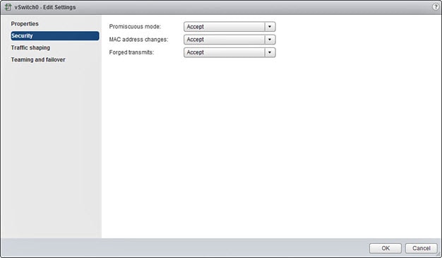
For a vSphere standard switch, the three elements of the Layer 2 Security policy are promiscuous mode, MAC address changes, and forged transmits. Threat Defense Virtual uses promiscuous mode to operate, and threat defense virtualrtual high availability depends on switching the MAC address between the active and the standby to operate correctly.

The default settings will block correct operation of the threat defense virtual. See the following required settings:

Table 4. vSphere Standard Switch Security Policy Options

Option

Required Setting

Action

Promiscuous Mode

Accept

You must edit the security policy for a vSphere standard switch in the vSphere Web Client and set the Promiscuous mode option to Accept.

Firewalls, port scanners, intrusion detection systems and so on, need to run in promiscuous mode.

MAC Address Changes

Accept

You should verify the security policy for a vSphere standard switch in the vSphere Web Client and confirm the MAC address changes option is set to Accept.

Forged Transmits

Accept

You should verify the security policy for a vSphere standard switch in the vSphere Web Client and confirm the Forged transmits option is set to Accept.


Note


We do not have any recommendations for NSX-T configuration of security policy settings for a vSphere standard switch as the VMware with NSX-T is not qualified.


Snort

  • If you are observing abnormal behavior such as Snort taking a long time to shut down, or the VM being slow in general or when a certain process is executed, collect logs from the threat defense virtual and the VM host. Collection of overall CPU usage, memory, I/O usage, and read/write speed logs will help troubleshoot the issues.

  • High CPU and I/O usage is observed when Snort is shutting down. If a number of threat defense virtual instances have been created on a single host with insufficient memory and no dedicated CPU, Snort will take a long time to shut down which will result in the creation of Snort cores.

Modify the Security Policy Settings for a vSphere Standard Switch

The default settings will block correct operation of the threat defense virtual.

Procedure


Step 1

In the vSphere Web Client, navigate to the host.

Step 2

On the Manage tab, click Networking, and select Virtual switches.

Step 3

Select a standard switch from the list and click Edit settings.

Step 4

Select Security and view the current settings.

Step 5

Accept promiscuous mode activation, MAC address changes, and forged transmits in the guest operating system of the virtual machines attached to the standard switch.

Figure 1. vSwitch Edit Settings

Step 6

Click OK.


What to do next

  • Ensure these settings are the same on all networks that are configured for management and failover (HA) interfaces on the threat defense virtual devices.

Plan the Interfaces

You can avoid reboots and configuration issues by planning the threat defense virtual vNIC and interface mapping in advance of deployment. The threat defense virtual deploys with 10 interfaces, and must be powered up at firstboot with at least 4 interfaces.

The threat defense virtual supports the vmxnet3 (default), ixgbe, and e1000 virtual network adapters. In addition, with a properly configured system, threat defense virtual also supports the ixgbe-vf driver for SR-IOV; see System Requirements for more information.


Important


Threat Defense Virtual on VMware now defaults to vmxnet3 interfaces when you create a virtual device. Previously, the default was e1000. If you are using e1000 interfaces, we strongly recommend you switch. The vmxnet3 device drivers and network processing are integrated with the ESXi hypervisor, so they use fewer resources and offer better network performance.


Interface Guidelines and Limitations

The following sections provide guidelines and limitations for the supported virtual network adapters used with threat defense virtual on VMware. It’s important to keep these guidelines in mind when planning your deployment.

General Guidelines

  • As previously stated, the threat defense virtual deploys with 10 interfaces, and must be powered up at firstboot with at least 4 interfaces. You need to assign a network to AT LEAST FOUR INTERFACES.

  • We recommend that you avoid using the HOLDING port group for the threat defense virtual interface. The HOLDING port group from vSphere causes inconsistent interface connectivity. A holding port is a generic port group which is assigned to a VLAN ID. This may lead to issues during HA formation with the secondary threat defense virtual device.

  • You do not need to use all 10 threat defense virtual interfaces; for interfaces you do not intend to use, you can simply leave the interface disabled within the threat defense virtual configuration.

  • Keep in mind that you cannot add more virtual interfaces to the virtual machine after deployment. If you delete some interfaces and then decide you want more, you’ll have to delete the virtual machine and start over.

  • You can optionally configure a data interface for the management center instead of the Management interface. The Management interface is a prerequisite for data interface management, so you still need to configure it in your initial setup. Note that the management center access from a data interface is not supported in High Availability deployments. For more information about configuring a data interface for the management center access, see the configure network management-data-interface command in Cisco Secure Firewall Threat Defense Command Reference.

  • The order of failover having two virtual NICs for the ESX port group, which is used in threat defense virtual inside interface or the failover high availability link, must be configured in a manner where one virtual NIC acts as an active uplink and the other as the standby uplink. This is necessary for the two VMs to ping each other or for the threat defense virtual high availability (HA) link to be up.

Default VMXNET3 Interfaces


Important


Threat Defense Virtual on VMware now defaults to vmxnet3 interfaces when you create a virtual device. Previously, the default was e1000. If you are using e1000 interfaces, we strongly recommend you switch. The vmxnet3 device drivers and network processing are integrated with the ESXi hypervisor, so they use fewer resources and offer better network performance.


  • The vmxnet3 driver uses two management interfaces. The first two Ethernet adapters must be configured as management interfaces; one for device management/registration, one that is reserved for internal use.

  • For vmxnet3, Cisco recommends using a host managed by VMware vCenter when using more than four vmxnet3 network interfaces. When deployed on standalone ESXi, additional network interfaces are not added to the virtual machine with sequential PCI bus addresses. When the host is managed with a VMware vCenter, the correct order can be obtained from the XML in the configuration CDROM. When the host is running standalone ESXi, the only way to determine the order of the network interfaces is to manually compare the MAC addresses seen on the threat defense virtual to the MAC addresses seen from the VMware configuration tool.

The following table describes the concordance of Network Adapter, Source Networks and Destination Networks for threat defense virtual for vmxnet3 and ixgbe interfaces.

Table 5. Source to Destination Network Mapping—VMXNET3 and IXGBE

Network Adapter

Source Networks

Destination Networks

Function

Network adapter 1

Management0-0

Management0/0

Management

Network adapter 2

Reserved for internal use.

Reserved for internal use.

Reserved for internal use.

Network adapter 3

GigabitEthernet0-0

GigabitEthernet0/0

Outside data

Network adapter 4

GigabitEthernet0-1

GigabitEthernet0/1

Inside data

Network adapter 5

GigabitEthernet0-2

GigabitEthernet0/2

Data traffic (Optional)

Network adapter 6

GigabitEthernet0-3

GigabitEthernet0/3

Data traffic (Optional)

Network adapter 7

GigabitEthernet0-4

GigabitEthernet0/4

Data traffic (Optional)

Network adapter 8

GigabitEthernet0-5

GigabitEthernet0/5

Data traffic (Optional)

Network adapter 9

GigabitEthernet0-6

GigabitEthernet0/6

Data traffic (Optional)

Network adapter 10

GigabitEthernet0-7

GigabitEthernet0/7

Data traffic (Optional)

IXGBE Interfaces

  • The ixgbe driver uses two management interfaces. The first two PCI devices must be configured as management interfaces; one for device management/registration, one reserved for internal use.

  • For ixgbe, the ESXi platform requires the ixgbe NIC to support the ixgbe PCI device. In addition, the ESXi platform has specific BIOS and configuration requirements that are needed to support ixgbe PCI devices. Refer to the Intel Technical Brief for more information.

  • The only ixgbe traffic interface types supported are routed and ERSPAN passive. This is due to VMware limitations with respect to MAC address filtering.

  • The ixgbe driver does not support failover (HA) deployments of threat defense virtual.

E1000 Interfaces


Important


Threat Defense Virtual on VMware now defaults to vmxnet3 interfaces when you create a virtual device. Previously, the default was e1000. If you are using e1000 interfaces, we strongly recommend you switch. The vmxnet3 device drivers and network processing are integrated with the ESXi hypervisor, so they use fewer resources and offer better network performance.


  • If you are upgrading your threat defense virtual to 6.4 and are using e1000 interfaces, you should replace the e1000 interfaces with either vmxnet3 or ixgbe interfaces for greater network throughput.

The following table describes the concordance of Network Adapter, Source Networks and Destination Networks for threat defense virtual for the default e1000 interfaces.

Table 6. Source to Destination Network Mapping—E1000 Interfaces

Network Adapter

Source Networks

Destination Networks

Function

Network adapter 1

Management0-0

Management0/0

Management

Network adapter 2

GigabitEthernet0-0

GigabitEthernet0/0

Outside data

Network adapter 3

GigabitEthernet0-1

GigabitEthernet0/1

Inside data

Network adapter 4

GigabitEthernet0-2

GigabitEthernet0/2

Data traffic (Required)

Network adapter 5

GigabitEthernet0-3

GigabitEthernet0/3

Data traffic (Optional)

Network adapter 6

GigabitEthernet0-4

GigabitEthernet0/4

Data traffic (Optional)

Network adapter 7

GigabitEthernet0-5

GigabitEthernet0/5

Data traffic (Optional)

Network adapter 8

GigabitEthernet0-6

GigabitEthernet0/6

Data traffic (Optional)

Network adapter 9

GigabitEthernet0-7

GigabitEthernet0/7

Data traffic (Optional)

Network adapter 10

GigabitEthernet0-8

GigabitEthernet0/8

Data traffic (Optional)

Configure VMXNET3 Interfaces


Important


Starting with the 6.4 release, the threat defense virtual and the management center virtual on VMware default to vmxnet3 interfaces when you create a virtual device. Previously, the default was e1000. If you are using e1000 interfaces, we strongly recommend you switch. The vmxnet3 device drivers and network processing are integrated with the ESXi hypervisor, so they use fewer resources and offer better network performance.


To change e1000 interfaces to vmxnet3, you must delete ALL interfaces and reinstall them with the vmxnet3 driver.

Although you can mix interfaces in your deployment (such as, e1000 interfaces on the management center and vmxnet3 interfaces on its managed virtual device), you cannot mix interfaces on the same virtual appliance. All sensing and management interfaces on the virtual appliance must be of the same type.

Procedure


Step 1

Power off the threat defense virtual or the management center virtual Machine.

To change the interfaces, you must power down the appliance.

Step 2

Right-click the threat defense virtual or the management center virtual Machine in the inventory and select Edit Settings.

Step 3

Select the applicable network adapters and then select Remove.

Step 4

Click Add to open the Add Hardware Wizard.

Step 5

Select Ethernet adapter and click Next.

Step 6

Select the vmxnet3 adapter and then choose network label.

Step 7

Repeat for all interfaces on the threat defense virtual.


What to do next

  • Power on the threat defense virtual or the management center virtual from the VMware console.

Adding Interfaces

You can have a total of 10 interfaces (1 management, 1 reserved for internal use, 8 data interfaces) when you deploy a threat defense virtual device. For data interfaces, make sure that the Source Networks map to the correct Destination Networks, and that each data interface maps to a unique subnet or VLAN.


Caution


You cannot add more virtual interfaces to the virtual machine and then have the threat defense virtual automatically recognize them. Adding interfaces to a virtual machine requires that you completely wipe out the threat defense virtual configuration. The only part of the configuration that remains intact is the management address and gateway settings.

If you need more physical-interface equivalents for a threat defense virtual device, you basically have to start over. You can either deploy a new virtual machine, or you can use the "Scan for Interface Changes, and Migrate an Interface" procedure in the Cisco Secure Firewall Device Manager Configuration Guide.

About VMware Deployment

You can deploy the threat defense virtual to a standalone ESXi server or, if you have vSphere vCenter, you can deploy using the vSphere Client or the vSphere Web Client. To successfully deploy the threat defense virtual you should be familiar with VMware and vSphere including vSphere networking, ESXi host setup and configuration, and virtual machine guest deployment.

Threat Defense Virtual for VMware is distributed using the Open Virtualization Format (OVF), which is a standard method of packaging and deploying virtual machines. VMware provides several methods to provision vSphere virtual machines. The optimal method for your environment depends on factors such as the size and type of your infrastructure and the goals that you want to achieve.

The VMware vSphere Web Client and the vSphere Client are interfaces to vCenter Server, ESXi hosts, and virtual machines. With the vSphere Web Client and the vSphere Client, you can connect remotely to vCenter Server. With the vSphere Client you can also connect directly to ESXi from any Windows system. The vSphere Web Client and the vSphere Client are the primary interfaces for managing all aspects of the vSphere environment. They also provide console access to virtual machines.

All administrative functions are available through the vSphere Web Client. A subset of those functions is available through the vSphere Client.

End-to-End Procedure

The following flowchart illustrates the workflow for deploying the threat defense virtual on ESXi host.

Workspace

Steps

Local Machine

Download ESXi OVF Template: Download Open Virtualization Format (OVF) package available from Cisco.com.

ESXi Host

(Optional) Disable Hyperthreading: Disable hyperthreading for your systems that run the threat defense virtual.

ESXi Host

(Optional) Verify CPU Support: Use the Linux command line to get information about the CPU hardware.

ESXi Host

Deploy the Threat Defense Virtual: Deploy the threat defense virtual appliance on a single ESXi host.

Threat Defense Virtual CLI

Complete the Initial Configuration: If you deployed with an ESXi OVF template, you must set up the threat defense virtual using the CLI.

Management Center or Device Manager

Manage the threat defense virtual:

The following flowchart illustrates the workflow for deploying the threat defense virtual on vSphere vCenter.

Workspace

Steps

Local Machine

Download VI OVF template: Download Open Virtualization Format (OVF) package available from Cisco.com.

vSphere vCenter

(Optional) Disable Hyperthreading: Disable hyperthreading for your systems that run the threat defense virtual.

vSphere vCenter

(Optional) Verify CPU Support: Use the Linux command line to get information about the CPU hardware.

vSphere vCenter

Deploy the Threat Defense Virtual: Deploy the threat defense virtual appliance on a single ESXi host.

Management Center or Device Manager

Manage the threat defense virtual:

Deploy the Threat Defense Virtual to vSphere vCenter

Use this procedure to deploy the threat defense virtual appliance to VMware vSphere vCenter. You can use the VMware Web Client (or vSphere Client) to deploy and configure the threat defense virtual machines.

Before you begin

  • You must have at least one network configured in vSphere (for management) before you deploy the threat defense virtual.

Procedure


Step 1

Log in to the vSphere Web Client (or the vSphere Client).

Step 2

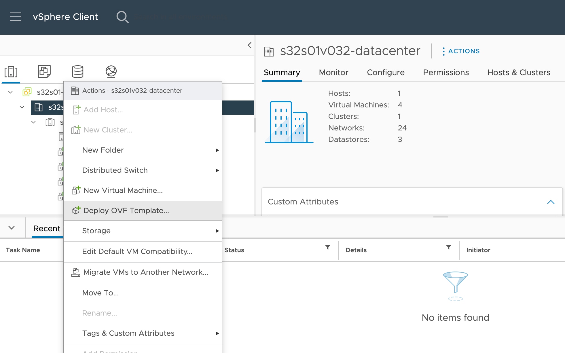
Using the vSphere Web Client (or the vSphere Client), deploy the OVF template file you downloaded earlier by clicking File > Deploy OVF Template.

The Deploy OVF Template wizard appears.

Step 3

Browse your file system for the OVF template source location and click Next.

Select the threat defense virtual VI OVF template:

Cisco_Secure_Firewall_Threat_Defense_Virtual-VI-X.X.X-xxx.ovf

where X.X.X-xxx is the version and build number of the archive file you downloaded.

Step 4

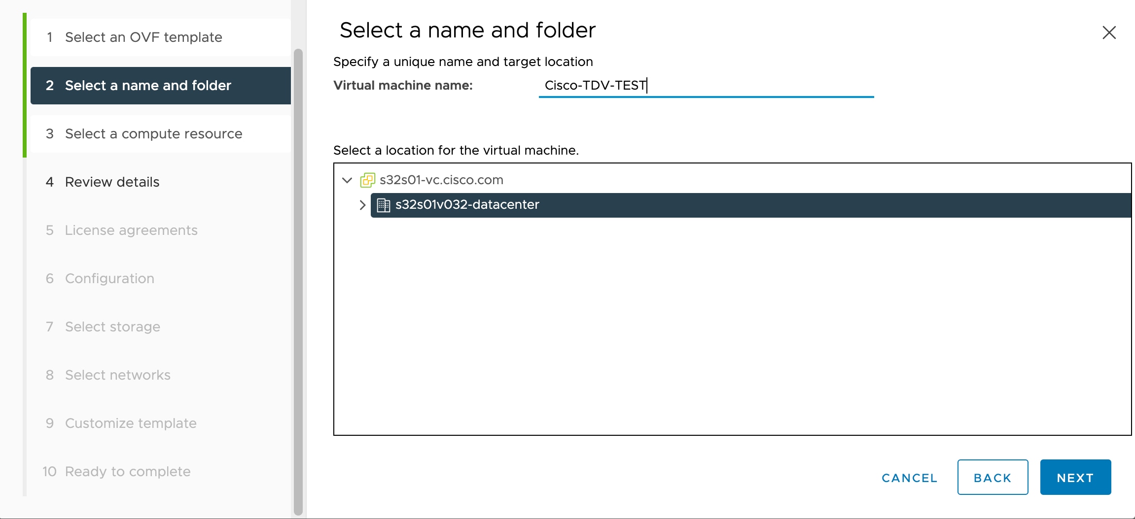
On the Name and Location page, enter a name for this deployment and select the location in the inventory (host or cluster) on which you want to deploy the threat defense virtual, then click Next. The name must be unique within the inventory folder and can contain up to 80 characters.

The vSphere Web Client presents the organizational hierarchy of managed objects in inventory views. Inventories are the hierarchical structure used by vCenter Server or the host to organize managed objects. This hierarchy includes all of the monitored objects in vCenter Server.

Step 5

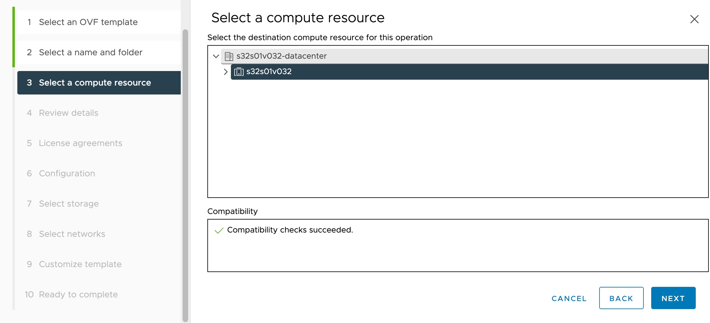
Navigate to, and select the resource pool where you want to run the threat defense virtual and click Next.

Note


This page appears only if the cluster contains a resource pool.

Step 6

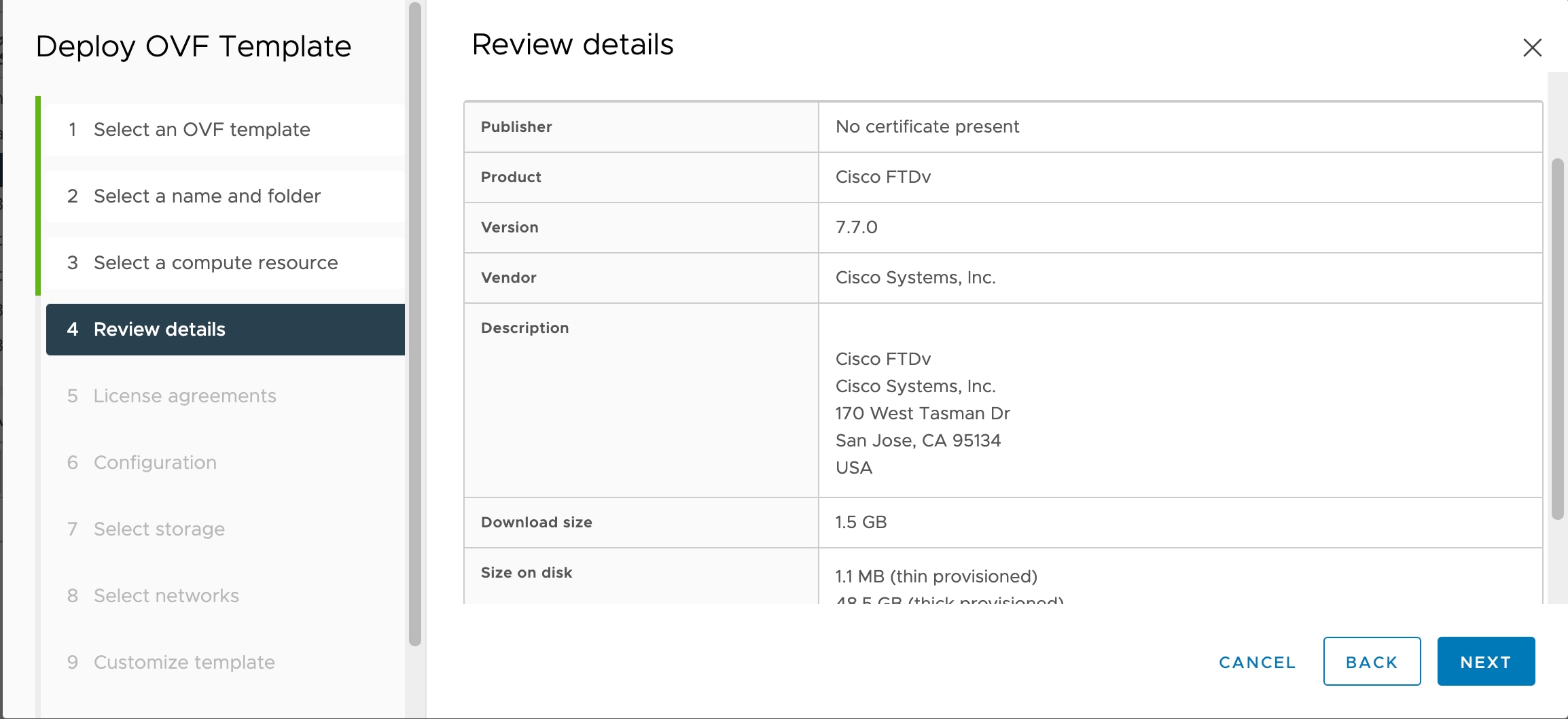
Review the OVF Template Details page and verify the OVF template information (product name, version, vendor, download size, size on disk, and description) and click Next.

Step 7

The End User License Agreement page appears. Review the license agreement packaged with the OVF template (VI templates only), click Accept to agree to the terms of the licenses and click Next.

Step 8

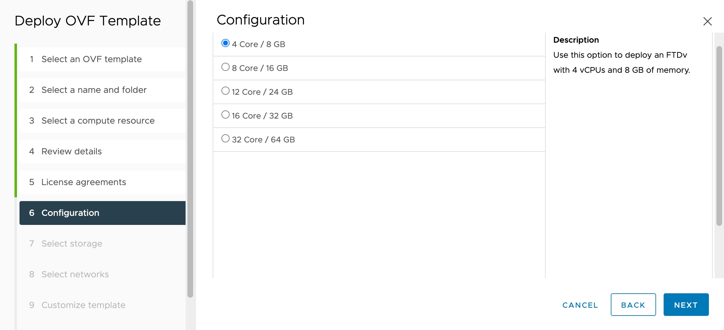
On the Configuration page, choose one of the supported vCPU/memory values from the Configuration options, and click Next.

Important


The threat defense virtual deploys with adjustable vCPU and memory resources.

Step 9

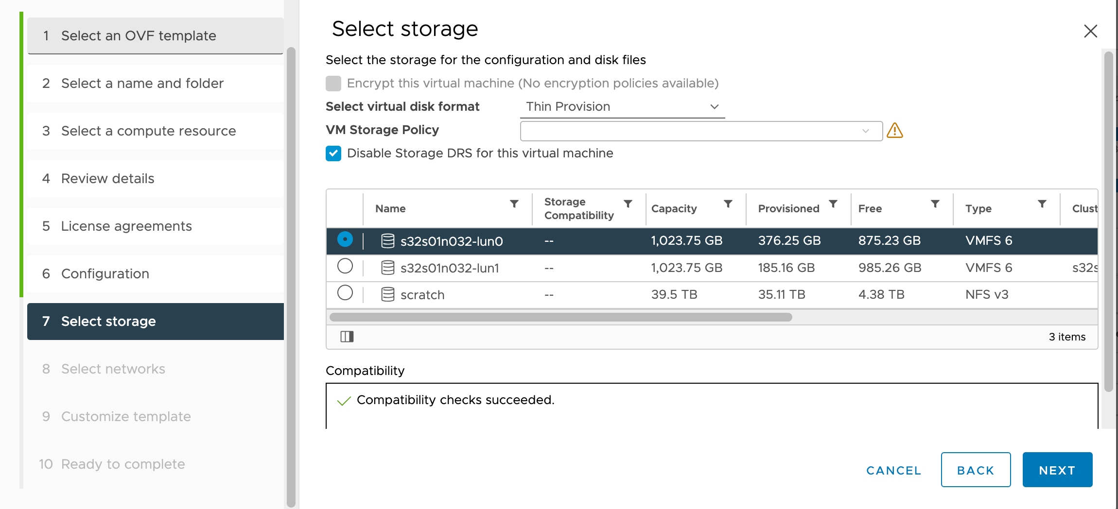
Select a Storage location to store the virtual machine files.

On this page, you select from datastores already configured on the destination cluster or host. The virtual machine configuration file and virtual disk files are stored on the datastore. Select a datastore large enough to accommodate the virtual machine and all of its virtual disk files.

Step 10

From the Select virtual disk format drop-down list, choose the disk format to store the virtual machine virtual disks, and click Next.

When you select Thick Provisioned, all storage is immediately allocated. When you select Thin Provisioned, storage is allocated on demand as data is written to the virtual disks. Thin provisioning can also reduce the amount of time it takes to deploy the virtual appliance.

Step 11

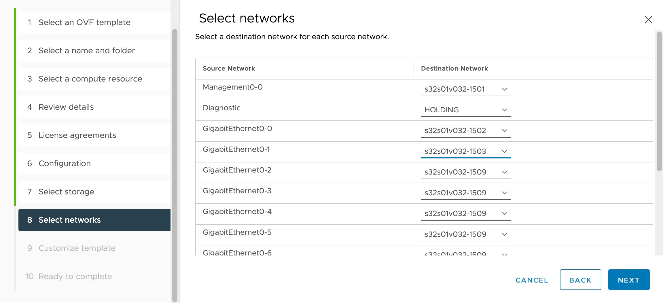
On the Select networks page, map the networks specified in the OVF template to networks in your inventory, and then click Next.

Ensure the Management0-0 interface is associated with a VM Network that is reachable from the Internet. Non-management interfaces are configurable from either the management center or from the device manager depending on your management mode.

Important


Threat Defense Virtual on VMware now defaults to vmxnet3 interfaces when you create a virtual device. Previously, the default was e1000. If you are using e1000 interfaces, we strongly recommend you switch. The vmxnet3 device drivers and network processing are integrated with the ESXi hypervisor, so they use fewer resources and offer better network performance.

The networks may not be in alphabetical order. If it is too difficult to find your networks, you can change the networks later from the Edit Settings dialog box. After you deploy, right-click the threat defense virtual instance, and choose Edit Settings. However, that screen does not show the threat defense virtual IDs (only Network Adapter IDs).

See the following concordance of Network Adapter, Source Networks and Destination Networks for the threat defense virtual interfaces (note these are the default vmxnet3 interfaces):

Table 7. Source to Destination Network Mapping—VMXNET3

Network Adapter

Source Networks

Destination Networks

Function

Network adapter 1

Management0-0

Management0/0

Management

Network adapter 2

Reserved for internal use.

Reserved for internal use.

Reserved for internal use.

Network adapter 3

GigabitEthernet0-0

GigabitEthernet0/0

Outside data

Network adapter 4

GigabitEthernet0-1

GigabitEthernet0/1

Inside data

Network adapter 5

GigabitEthernet0-2

GigabitEthernet0/2

Data traffic (Optional)

Network adapter 6

GigabitEthernet0-3

GigabitEthernet0/3

Data traffic (Optional)

Network adapter 7

GigabitEthernet0-4

GigabitEthernet0/4

Data traffic (Optional)

Network adapter 8

GigabitEthernet0-5

GigabitEthernet0/5

Data traffic (Optional)

Network adapter 9

GigabitEthernet0-6

GigabitEthernet0/6

Data traffic (Optional)

Network adapter 10

GigabitEthernet0-7

GigabitEthernet0/7

Data traffic (Optional)

You can have a total of 10 interfaces when you deploy the threat defense virtual. For data interfaces, make sure that the Source Networks map to the correct Destination Networks, and that each data interface maps to a unique subnet or VLAN. You do not need to use all threat defense virtual interfaces; for interfaces you do not intend to use, you can simply leave the interface disabled within the threat defense virtual configuration

Step 12

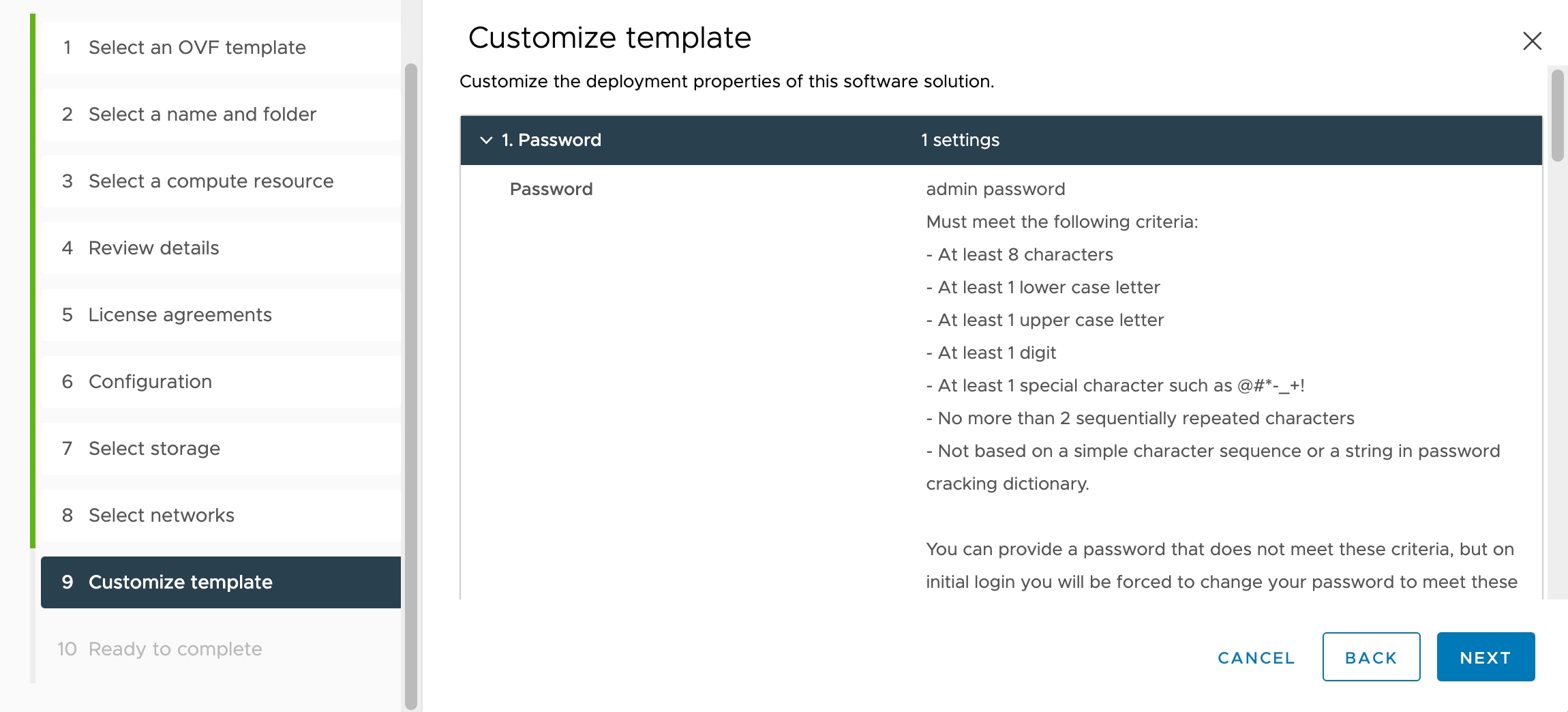
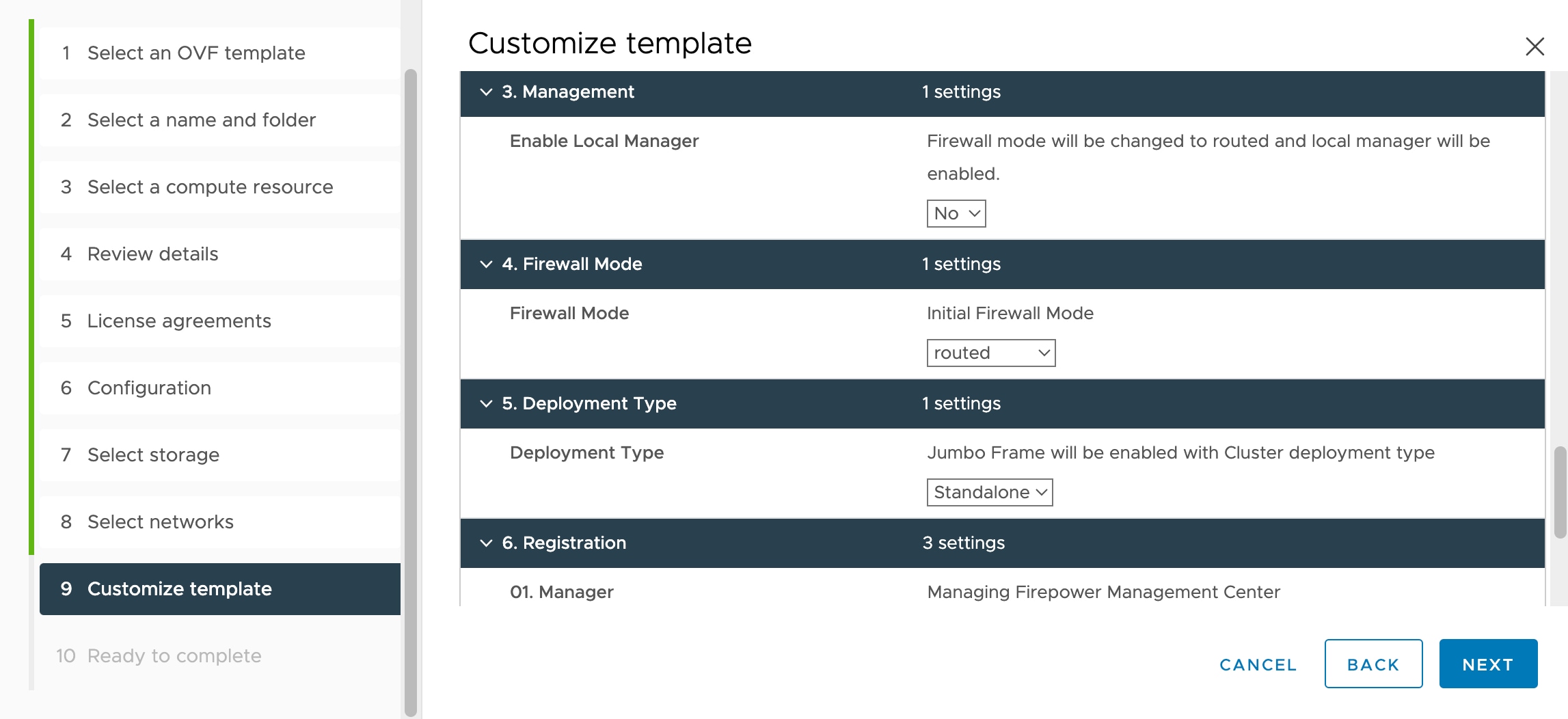
On the Customize templates properties page, set the user-configurable properties packaged with the OVF template (VI templates only):

  1. Password

    Set the password for threat defense virtual admin access.

  2. Network

    Set the network information, including the Fully Qualified Domain Name (FQDN), DNS, search domain, and network protocol (IPv4 or IPv6).

  3. Management

    Set the management mode. Click the drop-down arrow for Enable Local Manager and select Yes to use the integrated device manager web-based configuration tool. Select No to use a management center to manage this device. See How to Manage Secure Firewall Threat Defense Virtual Device for an overview of how to choose your management option.

  4. Firewall Mode

    Set the initial firewall mode. Click the drop-down arrow for Firewall Mode and choose one of the two supported modes, either Routed or Transparent.

    If you chose Yes for Enable Local Manager, you can only select Routed firewall mode. You cannot configure transparent firewall mode interfaces using the local device manager.

  5. Deployment Type

    Set the deployment type to Standalone or Cluster. Choose Cluster to enable jumbo-frame reservation, which is required for the cluster control link. Choose Standalone for a standalone or High Availability deployment. Note that if you deploy as a Standalone device, you can still use it in a cluster; however, enabling jumbo frames for clustering after deployment means you will have to restart.

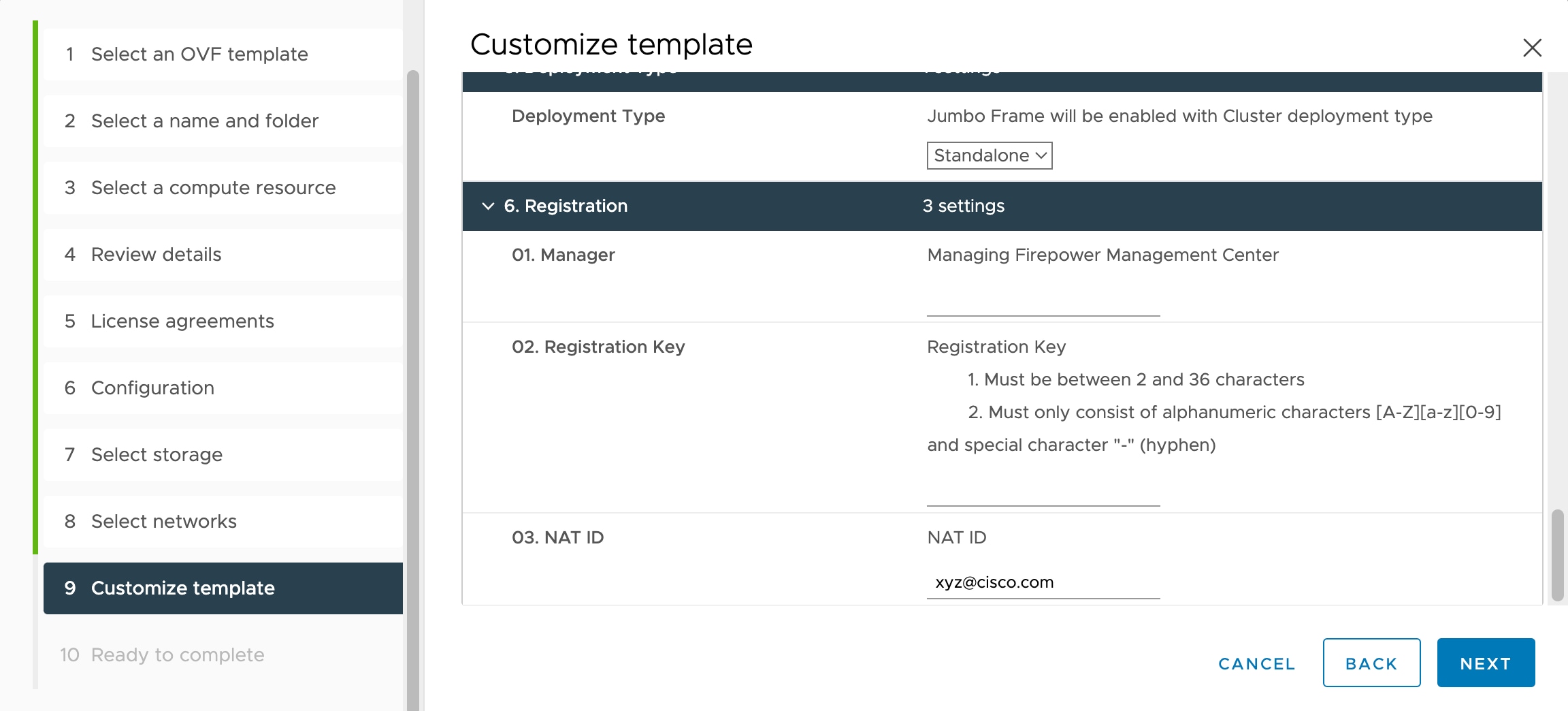
  6. Registration

    If you chose No for Enable Local Manager, you need to provide the required credentials to register this device to the managing Secure Firewall Management Center. Provide the following:

    • Managing Defense Center—Enter the host name or IP address of the management center.

    • Registration Key—The registration key is a user-generated one-time use key that must not exceed 37 characters. Valid characters include alphanumerical characters (A–Z, a–z, 0–9) and the hyphen (-). You will need to remember this registration key when you add the device to the management center.

    • NAT ID—If the threat defense virtual and the management center are separated by a Network Address Translation (NAT) device, and the management center is behind a NAT device, enter a unique NAT ID. This is a user-generated one-time use key that must not exceed 37 characters. Valid characters include alphanumerical characters (A–Z, a–z, 0–9) and the hyphen (-).

  7. Click Next.

Step 13

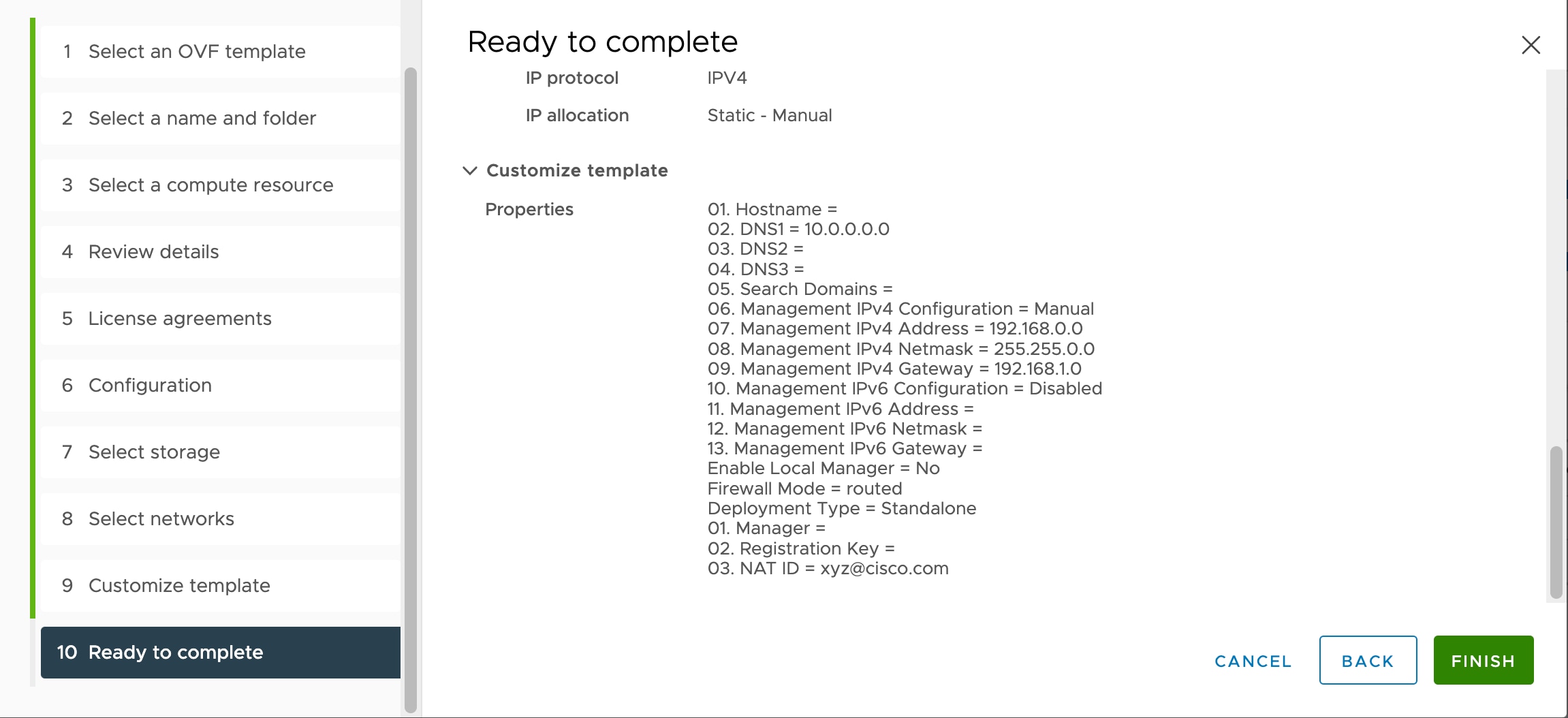
On the Ready to complete page, review and verify the displayed information. To begin the deployment with these settings, click Finish. To make any changes, click Back to navigate back through the screens.

Optionally, check the Power on after deployment option to power on the threat defense virtual, then click Finish.

After you complete the wizard, the vSphere Web Client processes the virtual machine; you can see the “Initialize OVF deployment” status in the Global Information area Recent Tasks pane.

When it is finished, you see the Deploy OVF Template completion status.

The threat defense virtual instance appears under the specified data center in the Inventory. Booting up the new VM could take up to 30 minutes.

Note


To successfully register the threat defense virtual with the Cisco Licensing Authority, the threat defense virtual requires Internet access. You might need to perform additional configuration after deployment to achieve Internet access and successful license registration.


What to do next

Your next steps depend on what management mode you chose.

See How to Manage Secure Firewall Threat Defense Virtual Device for an overview of how to choose your management option.

Prepare the Day 0 Configuration File for Cluster Deployment

You can prepare a Day 0 configuration file before you launch the threat defense virtual. This file is a text file that contains the initial configuration data that gets applied at the time a virtual machine is deployed. This initial configuration is placed into a text file named “day0-config” in a working directory you choose, and is manipulated into a day0.iso file that is mounted and read on first boot.


Important


The day0.iso file must be available during first boot.


If you deploy with a Day 0 configuration file, the process allows you to perform the entire initial setup for the threat defense virtual appliance. You can specify:

  • The End User License Agreement (EULA) acceptance.

  • A host name for the system.

  • A new administrator password for the admin account.

  • The management mode; see How to Manage Secure Firewall Threat Defense Virtual Device.

    Enter information for the management center fields (FmcIp, FmcRegKey, and FmcNatId). Leave fields empty for the management mode you are not using.

  • Network settings that allow the appliance to communicate on your management network.

  • The deployment type where you can specify whether you are deploying threat defense virtual as a cluster or standalone deployment.


Note


Linux machine is used in this example, but there are similar utilities for Windows.


Procedure


Step 1

Log in to the Linux host where you want to deploy threat defense virtual.

Step 2

Create a text file called “day0-config” for the threat defense virtual. In this text file, you must add Cluster deployment settings, network settings and information about managing the management center.

Example:

#Firepower Threat Defense
{
     
     "DeploymentType": "Cluster"

}

Enter the management center fields (FmcIp, FmcRegKey, and FmcNatId). For the management option you aren’t using, leave those fields blank.

Step 3

Generate the virtual CD-ROM by converting the text file to an ISO file:

Example:

/usr/bin/genisoimage -r -o day0.iso day0-config

Step 4

Log in to your target ESXi host.

Step 5

Open the virtual machine instance where you want to deploy the threat defense virtual in cluster mode.

Step 6

Browse and attach the day0 ISO image file that you have created to the CD/DVD drive 1 field under Hardware Configuration settings before you power on the virtual machine.

Step 7

Power on the virtual machine to deploy the threat defense virtual in cluster mode.


Deploy the Threat Defense Virtual to a vSphere ESXi Host

Use this procedure to deploy the threat defense virtual appliance on a single ESXi host. You can use the VMware Host Client (or vSphere Client) to manage single ESXi hosts and to perform administrative tasks such as basic virtualization operations, such as deploying and configuring threat defense virtual machines.


Note


It is important to know that the VMware Host Client is different from the vSphere Web Client, regardless of their similar user interfaces. You use the vSphere Web Client to connect to vCenter Server and manage multiple ESXi hosts, whereas you use the VMware Host Client to manage a single ESXi host.


For instructions on how to deploy the threat defense virtual appliance to a vCenter environment, see Deploy the Threat Defense Virtual to vSphere vCenter.

Before you begin

  • You must have at least one network configured in vSphere (for management) before you deploy the threat defense virtual.

Procedure


Step 1

Download the threat defense virtual install package for VMware ESXi from Cisco.com, and save it to your local management computer:

https://www.cisco.com/go/ftd-software

A Cisco.com login and Cisco service contract is required.

Step 2

Unpack the tar file into a working directory. Do not remove any files from the directory. The following files are included:

  • Cisco_Secure_Firewall_Threat_Defense_Virtual-VI-X.X.X-xxx.ovf—For vCenter deployments

  • Cisco_Secure_Firewall_Threat_Defense_Virtual-ESXi-X.X.X-xxx.ovf—For ESXi deployments.

  • Cisco_Secure_Firewall_Threat_Defense_Virtual-X.X.X-xxx.vmdk—VMware virtual disk file.

  • Cisco_Secure_Firewall_Threat_Defense_Virtual-VI-X.X.X-xxx.mf—Manifest file for vCenter deployments.

  • Cisco_Secure_Firewall_Threat_Defense_Virtual-ESXi-X.X.X-xxx.mf—Manifest file for ESXi deployments.

where X.X.X-xx is the version and build number of the archive file you downloaded.

Step 3

In a browser, enter the ESXi target host name or IP address using the format http://host-name/ui or http://host-IP-address/ui.

A log in screen appears.

Step 4

Enter the administrator user name and password.

Step 5

Click Login to continue.

You are now logged in to your target ESXi host.

Step 6

Right-click on Host in the VMware Host Client inventory and select Create/Register VM.

The New Virtual Machine wizard opens.

Step 7

On the Select creation type page of the wizard, select Deploy a virtual machine from an OVF or OVA file and click Next.

Step 8

On the Select OVF and VMDK files page of the wizard:

  1. Enter a name for your threat defense virtual machine.

    Virtual machine names can contain up to 80 characters and must be unique within each ESXi instance.

  2. Click the blue pane, browse to the directory where you unpacked the threat defense virtual tar file, and choose the ESXi OVF template and the accompanying VMDK file:

    Cisco_Secure_Firewall_Threat_Defense_Virtual-ESXi-X.X.X-xxx.ovf

    Cisco_Secure_Firewall_Threat_Defense_Virtual-X.X.X-xxx.vmdk

    where X.X.X-xx is the version and build number of the archive file you downloaded.

    Attention


    Make sure you select the ESXi OVF.

Step 9

Click Next.

Your local system storage opens.

Step 10

Choose a datastore from the list of accessible datastores on the Select storage page of the wizard.

The datastore stores the virtual machine configuration files and all of the virtual disks. Each datastore might have a different size, speed, availability, and other properties.

Step 11

Click Next.

Step 12

Configure the Deployment options that come packaged with the ESXi OVF for the threat defense virtual:

  1. Network Mapping—Map the networks specified in the OVF template to networks in your inventory, and then select Next.

    Ensure the Management0-0 interface is associated with a VM Network that is reachable from the Internet. Non-management interfaces are configurable from either the management center or from the device manager depending on your management mode.

    Important


    Threat Defense Virtual on VMware now defaults to vmxnet3 interfaces when you create a virtual device. Previously, the default was e1000. If you are using e1000 interfaces, we strongly recommend you switch. The vmxnet3 device drivers and network processing are integrated with the ESXi hypervisor, so they use fewer resources and offer better network performance.

    The networks may not be in alphabetical order. If it is too difficult to find your networks, you can change the networks later from the Edit Settings dialog box. After you deploy, right-click the threat defense virtual instance, and choose Edit Settings. However, that screen does not show the threat defense virtual IDs (only Network Adapter IDs).

    See the following concordance of Network Adapter, Source Networks and Destination Networks for threat defense virtual interfaces (note these are the default vmxnet3 interfaces):

    Table 8. Source to Destination Network Mapping—VMXNET3

    Network Adapter

    Source Networks

    Destination Networks

    Function

    Network adapter 1

    Management0-0

    Management0/0

    Management

    Network adapter 2

    Reserved for internal use.

    Reserved for internal use.

    Reserved for internal use.

    Network adapter 3

    GigabitEthernet0-0

    GigabitEthernet0/0

    Outside data

    Network adapter 4

    GigabitEthernet0-1

    GigabitEthernet0/1

    Inside data

    Network adapter 5

    GigabitEthernet0-2

    GigabitEthernet0/2

    Data traffic (Optional)

    Network adapter 6

    GigabitEthernet0-3

    GigabitEthernet0/3

    Data traffic (Optional)

    Network adapter 7

    GigabitEthernet0-4

    GigabitEthernet0/4

    Data traffic (Optional)

    Network adapter 8

    GigabitEthernet0-5

    GigabitEthernet0/5

    Data traffic (Optional)

    Network adapter 9

    GigabitEthernet0-6

    GigabitEthernet0/6

    Data traffic (Optional)

    Network adapter 10

    GigabitEthernet0-7

    GigabitEthernet0/7

    Data traffic (Optional)

    You can have a total of 10 interfaces when you deploy the threat defense virtual. For data interfaces, make sure that the Source Networks map to the correct Destination Networks, and that each data interface maps to a unique subnet or VLAN. You do not need to use all threat defense virtual interfaces; for interfaces you do not intend to use, you can simply leave the interface disabled within the threat defense virtual configuration

  2. Disk provisioning—Select the disk format to store the virtual machine virtual disks.

    When you select Thick provisioned, all storage is immediately allocated. When you select Thin provisioned, storage is allocated on demand as data is written to the virtual disks. Thin provisioning can also reduce the amount of time it takes to deploy the virtual appliance.

Step 13

On the Ready to complete page of the New virtual machine wizard, review the configuration settings for the virtual machine.

  1. (Optional) Click Back to go back and review or modify the wizard settings.

  2. (Optional) Click Cancel to discard the creation task and close the wizard.

  3. Click Finish to complete the creation task and close the wizard.

    After you complete the wizard, the ESXi host processes the VM; you can see the deployment status in the Recent Tasks pane. A successful deployment shows Completed successfully under the Results column.

    The new threat defense virtual virtual machine instance then appears under the Virtual Machines inventory of the ESXi host. Booting up the new virtual machine could take up to 30 minutes.

    Note


    To successfully register the threat defense virtual with the Cisco Licensing Authority, the threat defense virtual requires Internet access. You might need to perform additional configuration after deployment to achieve Internet access and successful license registration.


What to do next

Complete the Threat Defense Virtual Setup Using the CLI

If you deployed with an ESXi OVF template, you must set up the threat defense virtual using the CLI. Threat Defense Virtual appliances do not have web interfaces. You can also use the CLI to configure System-required settings if you deployed with a VI OVF template and did not use the setup wizard during deployment.


Note


If you deployed with a VI OVF template and used the setup wizard, your virtual device is configured and no further device configuration is required. Your next steps depend on which management mode you choose.


When you first log into a newly configured device, you must read and accept the EULA. Then, follow the setup prompts to change the administrator password, and configure the device’s network settings and firewall mode.

When following the setup prompts, for multiple-choice questions, your options are listed in parentheses, such as (y/n). Defaults are listed in square brackets, such as [y]. Press Enter to confirm a choice.

Procedure


Step 1

Open the VMware console.

Step 2

At the firepower login prompt, log in with the default credentials of username admin and the password Admin123.

Step 3

When the threat defense virtual system boots, a setup wizard prompts you for the following information required to configure the system:

  • Accept EULA

  • New admin password

  • IPv4 or IPv6 configuration

  • IPv4 or IPv6 DHCP settings

  • Management port IPv4 address and subnet mask, or IPv6 address and prefix

  • System name

  • Default gateway

  • DNS setup

  • HTTP proxy

  • Management mode (local management uses the device manager).

Step 4

Review the Setup wizard settings. Defaults or previously entered values appear in brackets. To accept previously entered values, press Enter.

The VMware console may display messages as your settings are implemented.

Step 5

Complete the system configuration as prompted.

Step 6

Verify the setup was successful when the console returns to the firepower # prompt.

Note

 
To successfully register the threat defense virtual with the Cisco Licensing Authority, the threat defense virtual requires Internet access. You might need to perform additional configuration after deployment to achieve Internet access and successful license registration.

What to do next

Your next steps depend on what management mode you chose.

See How to Manage Secure Firewall Threat Defense Virtual Device for an overview of how to choose your management option.

Increasing Performance on ESXi Configurations

You can increase the performance for the threat defense virtual in the ESXi environment by tuning the ESXi host CPU configuration settings. The Scheduling Affinity option gives you control over how virtual machine CPUs are distributed across the host's physical cores (and hyperthreads if hyperthreading is enabled). By using this feature, you can assign each virtual machine to processors in the specified affinity set.

See the following VMware documents for more information:

NUMA Guidelines

Non-Uniform Memory Access (NUMA) is a shared memory architecture that describes the placement of main memory modules with respect to processors in a multiprocessor system. When a processor accesses memory that does not lie within its own node (remote memory), data must be transferred over the NUMA connection at a rate that is slower than it would be when accessing local memory.

The x86 server architecture consists of multiple sockets and multiple cores within a socket. Each CPU socket along with its memory and I/O is referred to as a NUMA node. To efficiently read packets from memory, guest applications and associated peripherals (such as the NIC) should reside within the same node.

For optimum threat defense virtual performance:

  • The threat defense virtual VM must run on a single numa node. If a single threat defense virtual is deployed so that is runs across 2 sockets, the performance will be significantly degraded.

  • An 8-core threat defense virtual requires that each socket on the host CPU have a minimum of 8 cores per socket. Consideration must be given to other VMs running on the server.

  • A 16-core threat defense virtual requires that each socket on the host CPU have a minimum of 16 cores per socket. Consideration must be given to other VMs running on the server.

  • The NIC should be on same NUMA node as threat defense virtual VM.

More information about using NUMA systems with ESXi can be found in the VMware document vSphere Resource Management for your VMware ESXi version. To check for more recent editions of this and other relevant documents, see http://www.vmware.com/support/pubs....

SR-IOV Interface Provisioning

Single Root I/O Virtualization (SR-IOV) allows multiple VMs running a variety of guest operating systems to share a single PCIe network adapter within a host server. SR-IOV allows a VM to move data directly to and from the network adapter, bypassing the hypervisor for increased network throughput and lower server CPU burden. Recent x86 server processors include chipset enhancements, such as Intel VT-d technology, that facilitate direct memory transfers and other operations required by SR-IOV.

The SR-IOV specification defines two device types:

  • Physical Function (PF)—Essentially a static NIC, a PF is a full PCIe device that includes SR-IOV capabilities. PFs are discovered, managed, and configured as normal PCIe devices. A single PF can provide management and configuration for a set of virtual functions (VFs).

  • Virtual Function (VF)—Similar to a dynamic vNIC, a VF is a full or lightweight virtual PCIe device that provides at least the necessary resources for data movements. A VF is not managed directly but is derived from and managed through a PF. One or more VFs can be assigned to a VM.

VFs are capable of providing up to 10 Gbps connectivity to threat defense virtual machines within a virtualized operating system framework. This section explains how to configure VFs in a VMware environment.

Best Practices for SR-IOV Interfaces

Guidelines for SR-IOV Interfaces

VMware vSphere 5.1 and later releases support SR-IOV in an environment with specific configurations only. Some features of vSphere are not functional when SR-IOV is enabled.

In addition to the System Requirements for the threat defense virtual and SR-IOV, you should review the Supported Configurations for Using SR-IOV in the VMware documentation for more information about requirements, supported NICs, availability of features, and upgrade requirements for VMware and SR-IOV.

Threat Defense Virtual on VMware using the SR-IOV interface supports mixing of interface types. You can use SR-IOV or VMXNET3 for the management interface and SR-IOV for the data interface.

This section shows various setup and configuration steps for provisioning SR-IOV interfaces on a VMware system. The information in this section was created from devices in a specific lab environment, using VMware ESXi 6.0 and vSphere Web Client, a Cisco UCS C Series server, and an Intel Ethernet Server Adapter X520 - DA2.

Limitations for SR-IOV Interfaces

When the threat defense virtual is booted, be aware that SR-IOV interfaces can show up in reverse order when compared to the order presented in ESXi. This could cause interface configuration errors that result in a lack of network connectivity for a particular threat defense virtual machine.


Caution


It is important that you verify the interface mapping before you begin configuring the SR-IOV network interfaces on the threat defense virtual. This ensures that the network interface configuration will apply to the correct physical MAC address interface on the VM host.


After the threat defense virtual boots, you can confirm which MAC address maps to which interface. Use the show interface command to see detailed interface information, including the MAC address for an interface. Compare the MAC address to the results of the show kernel ifconfig command to confirm the correct interface assignment.

NOTE:

Limitations of using ixgbe-vf Interfaces

Be aware of the following limitations when using ixgbe-vf interfaces:

  • The guest VM is not allowed to set the VF to promiscuous mode. Because of this, transparent mode is not supported when using ixgbe-vf.

  • The guest VM is not allowed to set the MAC address on the VF. Because of this, the MAC address is not transferred during HA like it is done on other threat defense virtual platforms and with other interface types. HA failover works by transferring the IP address from active to standby.


    Note


    This limitation is applicable to the i40e-vf interfaces too.


  • The Cisco UCS-B server does not support the ixgbe-vf vNIC.

  • In a failover setup, when a paired threat defense virtual (primary unit) fails, the standby threat defense virtual unit takes over as the primary unit role and its interface IP address is updated with a new MAC address of the standby threat defense virtual unit. Thereafter, the threat defense virtual sends a gratuitous Address Resolution Protocol (ARP) update to announce the change in MAC address of the interface IP address to other devices on the same network. However, due to incompatibility with these types of interfaces, the gratuitous ARP update is not sent to the global IP address that is defined in the NAT or PAT statements for translating the interface IP address to global IP addresses.

Check the ESXi Host BIOS

Before you begin

To deploy the threat defense virtual with SR-IOV interfaces on VMware, virtualization needs to be supported and enabled. VMware provides several methods of verifying virtualization support, including their online Compatibility Guide for SR-IOV support as well as a downloadable CPU identification utility that detects whether virtualization is enabled or disabled.

You can also determine if virtualization is enabled in the BIOS by logging into the ESXi host.

Procedure


Step 1

Log in to the ESXi Shell using one of the following methods:

  • If you have direct access to the host, press Alt+F2 to open the login page on the machine's physical console.
  • If you are connecting to the host remotely, use SSH or another remote console connection to start a session on the host.

Step 2

Enter a user name and password recognized by the host.

Step 3

Run the following commands:

esxcfg-info|grep "\----\HV Support"
  • The output of the HV Support command indicates the type of hypervisor support available. These are the descriptions for the possible values:

  • 0 - VT/AMD-V indicates that support is not available for this hardware.

  • 1 - VT/AMD-V indicates that VT or AMD-V might be available but it is not supported for this hardware.

  • 2 - VT/AMD-V indicates that VT or AMD-V is available but is currently not enabled in the BIOS.

  • 3 - VT/AMD-V indicates that VT or AMD-V is enabled in the BIOS and can be used.

~ # esxcfg-info|grep "\----\HV Support"
         |----HV Support...........................3

The value 3 indicates that virtualization is supported and enabled.


What to do next

Enable SR-IOV on the host physical adapter.

Enable SR-IOV on the Host Physical Adapter

Before you can connect virtual machines to virtual functions, use the vSphere Web Client to enable SR-IOV and set the number of virtual functions on your host.

Before you begin

  • Make sure you have an SR-IOV-compatible network interface card (NIC) installed; see System Requirements.

Procedure


Step 1

In the vSphere Web Client, navigate to the ESXi host where you want to enable SR-IOV.

Step 2

On the Manage tab, click Networking and choose Physical adapters.

You can look at the SR-IOV property to see whether a physical adapter supports SR-IOV.

Step 3

Select the physical adapter and click Edit adapter settings.

Step 4

Under SR-IOV, select Enabled from the Status drop-down menu.

Step 5

In the Number of virtual functions text box, type the number of virtual functions that you want to configure for the adapter.

Note


We recommend that you DO NOT use more than 1 VF per interface. Performance degradation is likely to occur if you share the physical interface with multiple virtual functions.

Step 6

Click OK.

Step 7

Restart the ESXi host.

The virtual functions become active on the NIC port represented by the physical adapter entry. They appear in the PCI Devices list in the Settings tab for the host.


What to do next

  • Create a standard vSwitch to manage the SR-IOV functions and configurations.

Create a vSphere Switch

Create a vSphere switch to manage the SR-IOV interfaces.

Procedure


Step 1

In the vSphere Web Client, navigate to the ESXi host.

Step 2

Under Manage select Networking, and then select Virtual switches.

Step 3

Click the Add host networking icon, which is the green globe icon with the plus (+) sign.

Step 4

Select a Virtual Machine Port Group for a Standard Switch connection type and click Next.

Step 5

Choose New standard switch and click Next.

Step 6

Add physical network adapters to the new standard switch.

  1. Under Assigned adapters, click the green plus (+) sign to Add adapters.

  2. Select the corresponding network interface for SR-IOV from the list. For example, Intel(R) 82599 10 Gigabit Dual Port Network Connection.

  3. From the Failover order group drop-down menu, select from the Active adapters.

  4. Click OK.

Step 7

Enter a Network label for the SR-IOV vSwitch and click Next.

Step 8

Review your selections on the Ready to complete page, then click Finish.


Figure 2. New vSwitch with an SR-IOV Interface attached

What to do next

  • Review the compatibility level of your virtual machine.

Upgrade the Compatibility Level for Virtual Machines

The compatibility level determines the virtual hardware available to the virtual machine, which corresponds to the physical hardware available on the host machine. The threat defense virtual VM needs to be at Hardware Level 10 or higher. This will expose the SR-IOV passthough feature to the threat defense virtual. This procedure upgrades the threat defense virtual to the latest supported virtual hardware version immediately.

For information about virtual machine hardware versions and compatibility, see the vSphere Virtual Machine Administration documentation.

Procedure


Step 1

Log in to the vCenter Server from the vSphere Web Client.

Step 2

Locate the threat defense virtual machine that you want to modify.

  1. Select a datacenter, folder, cluster, resource pool, or host and click the Related Objects tab.

  2. Click Virtual Machines and select the threat defense virtual machine from the list.

Step 3

Power off the selected virtual machine.

Step 4

Right-click the threat defense virtual and select Actions > All vCenter Actions > Compatibility > Upgrade VM Compatibility.

Step 5

Click Yes to confirm the upgrade.

Step 6

Choose the ESXi 5.5 and later option for the virtual machines compatiblity.

Step 7

(Optional) Select Only upgrade after normal guest OS shutdown.

The selected virtual machine is upgraded to the corresponding hardware version for the Compatibility setting that you chose, and the new hardware version is updated in the Summary tab of the virtual machine.


What to do next

  • Associate the threat defense virtual with a virtual function through an SR-IOV passthrough network adapter.

Assign the SR-IOV NIC to the Threat Defense Virtual

To ensure that the threat defense virtual machine and the physical NIC can exchange data, you must associate the threat defense virtual with one or more virtual functions as SR-IOV passthrough network adapters. The following procedure explains how to assign the SR-IOV NIC to the threat defense virtual machine using the vSphere Web Client.

Procedure


Step 1

Log in to the vCenter Server from the vSphere Web Client.

Step 2

Locate the threat defense virtual machine you wish to modify.

  1. Select a datacenter, folder, cluster, resource pool, or host and click the Related Objects tab.

  2. Click Virtual Machines and select the threat defense virtual machine from the list.

Step 3

On the Manage tab of the virtual machine, select Settings > VM Hardware.

Step 4

Click Edit and choose the Virtual Hardware tab.

Step 5

From the New device drop-down menu, select Network and click Add.

A New Network interface appears.

Step 6

Expand the New Network section and select an available SRIOV option.

Step 7

From the Adapter Type drop-down menu, select SR-IOV passthrough.

Step 8

From the Physical function drop-down menu, select the physical adapter that corresponds to the passthrough virtual machine adapter.

Step 9

Power on the virtual machine.


When you power on the virtual machine, the ESXi host selects a free virtual function from the physical adapter and maps it to the SR-IOV passthrough adapter. The host validates all properties of the virtual machine adapter and the underlying virtual function.


Note


Using SR-IOV interfaces as passive interfaces on the threat defense virtual is not supported on some Intel network adapters (such as Intel X710 or 82599) using SR-IOV drivers due to a promiscuous mode restriction. In such cases, use a network adapter that supports this functionality. See Intel Ethernet Products for more information on Intel network adapters.