- Title Page
- Introduction to the FireSIGHT System
- Deploying on a Management Network
- Deploying Managed Devices
- Installing a FireSIGHT System Appliance
- Setting Up a FireSIGHT System Appliance
- Using the LCD Panel on a Series 3 Device
- Hardware Specifications
- Restoring a FireSIGHT System Appliance to Factory Defaults
- Power Requirements for FirePOWER Devices
- Using SFP Transceivers in 3D71x5 and AMP7150 Devices
- Inserting and Removing 8000 Series Modules
- Scrubbing the Hard Drive
- Preconfiguring FireSIGHT System Appliances
- Glossary
- Included Items
- Security Considerations
- Identifying the Management Interfaces
- Identifying the Sensing Interfaces
Installing a FireSIGHT System Appliance
FireSIGHT System appliances are easily installed on your network as part of a larger FireSIGHT System deployment. You install devices on network segments to inspect traffic and generate intrusion events based on the intrusion policy applied to it. This data is transmitted to a Defense Center, which manages one or more devices to correlate data across your full deployment, and coordinate and respond to threats to your security.
You can use multiple management interfaces to improve performance or to isolate and manage traffic from two different networks. You configure the default management interface ( eth0 ) during the initial installation. You can configure additional management interfaces after installation from the user interface. For more information, see FireSIGHT System User Guide .
You can pre-configure multiple appliances at one location to be used in different deployment locations. For guidance on pre-configuring, see Preconfiguring FireSIGHT System Appliances.

Note![]() See the ASA documentation for information on installing ASA FirePOWER devices.
See the ASA documentation for information on installing ASA FirePOWER devices.
See the following sections for more information about installing a FireSIGHT System appliance:
Included Items
The following is a list of components that ship with FireSIGHT System appliances. As you unpack the system and the associated accessories, check that your package contents are complete as follows:
- one FireSIGHT System appliance
- power cord (two power cords are included with appliances that include redundant power supplies)
- Category 5e Ethernet straight-through cables: one for a Defense Center; two for a managed device
- one rack-mounting kit (required tray and rack-mounting kit available separately for the 3D7010, 3D7020, 3D7030, and 3D7050)
Security Considerations
Before you install your appliance, Cisco recommends that you consider the following:
- Locate your FireSIGHT System appliance in a lockable rack within a secure location that prevents access by unauthorized personnel.
- Allow only trained and qualified personnel to install, replace, administer, or service the FireSIGHT System appliance.
- Always connect the management interface to a secure internal management network that is protected from unauthorized access.
- Identify the specific workstation IP addresses that can be allowed to access appliances. Restrict access to the appliance to only those specific hosts using Access Lists within the appliance’s system policy. For more information, see the FireSIGHT System User Guide .
Identifying the Management Interfaces
You connect each appliance in your deployment to the network using the management interface. This allows the Defense Center to communicate with and administer the devices it manages.
FireSIGHT System appliances are delivered on different hardware platforms. Make sure you refer to the correct illustration for your appliance as you follow the installation procedure:
- FireSIGHT Defense Center 750
- FireSIGHT Defense Center 1500
- FireSIGHT Defense Center 3500
- FireSIGHT Defense Center 4000
- FirePOWER 7000 Series
- FirePOWER 8000 Series
FireSIGHT Defense Center 750
The DC750 is available as a 1U appliance. The following illustration of the rear of the chassis indicates the location of the default management interface (1) on a DC750.

FireSIGHT Defense Center 1500
The DC1500 is available as a 1U appliance. The following illustration of the rear of the chassis indicates the location of the default management interface (1) on a DC1500.

FireSIGHT Defense Center 3500
The DC3500 is available as a 1U appliance. The following illustration of the rear of the chassis indicates the location of the default management interface (1) on a DC3500.

FireSIGHT Defense Center 4000
The DC4000 is available as a 1U appliance. The following illustration of the rear of the chassis indicates the location of the default management interface (1) on a DC4000.

FirePOWER 7000 Series
The 3D7010, 3D7020, 3D7030, and 3D7050 are 1U appliances that are one-half the width of the chassis tray. The following illustration of the front of the chassis indicates the location (1) of the default management interface.

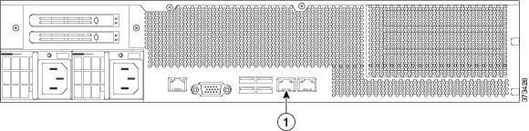
The 3D7110/7120, the 3D7115/7125, and the AMP7150 are available as 1U appliances. The following illustration of the rear of the chassis indicates the location (1) of the default management interface.

FirePOWER 8000 Series
The 3D8120, 3D8130, 3D8140, and AMP8150 are available as 1U appliances. The following illustration of the rear of the chassis indicates the location (1) of the default management interface.

The 3D8250 is available as a 2U appliance. The 3D8260, 3D8270, and 3D8290 are available as 2U appliances with one, two, or three secondary 2U appliances. The following illustration of the rear of the chassis indicates the location (1) of the default management interface for each 2U appliance.
The 3D8350 is available as a 2U appliance. The 3D8360, 3D8370, and 3D8390 are available as 2U appliances with one, two, or three secondary 2U appliances. The following illustration of the rear of the chassis indicates the location of the default management interface (1) for each 2U appliance.

Identifying the Sensing Interfaces
Managed devices connect to network segments using sensing interfaces. The number of segments each device can monitor depends on the number of sensing interfaces on the device and the type of connection (passive, inline, routed, or switched) that you want to use on the network segment.
The following sections describe the sensing interfaces for each managed device:
- To locate the sensing interfaces on the 7000 Series, see FirePOWER 7000 Series.
- To locate the module slots on the 8000 Series on the FirePOWER 8000 Series.
- To locate the sensing interfaces on the 8000 Series NetMods, see 8000 Series Modules.
For information on connection types, see Understanding Sensing Interfaces.
FirePOWER 7000 Series
The 7000 Series is available in the following configurations:
- 1U device one-half the width of the rack tray with eight copper interfaces, each with configurable bypass capability.
- 1U device with either eight copper interfaces or eight fiber interfaces, each with configurable bypass capability
- 1U device with four copper interfaces with configurable bypass capability and eight small form-factor pluggable (SFP) ports without bypass capability
3D7010, 3D7020, 3D7030, and 3D7050
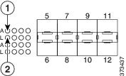
The 3D7010, 3D7020, 3D7030, and 3D7050 are delivered with eight copper port sensing interfaces, each with configurable bypass capability. The following illustration of the front of the chassis indicates the location of the sensing interfaces.
Figure 4-2 Eight Port 1000BASE-T Copper Configurable Bypass Interfaces

|
|
|
||
|
|
|
You can use these connections to passively monitor up to eight separate network segments. You can also use paired interfaces in inline or inline with bypass mode to deploy the device as an intrusion prevention system on up to four networks.

|
|
|
||
|
|
|
If you want to take advantage of the device’s automatic bypass capability, you must connect two interfaces vertically (interfaces 1 and 2, 3 and 4, 5 and 6, or 7 and 8) to a network segment. Automatic bypass capability allows traffic to flow even if the device fails or loses power. After you cable the interfaces, you use the web interface to configure a pair of interfaces as an inline set and enable bypass mode on the inline set.
3D7110 and 3D7120
The 3D7110 and 3D7120 are delivered with eight copper port sensing interfaces (see Figure 4-3), or eight fiber port sensing interfaces (see Figure 4-5), each with configurable bypass capability. The following illustrations of the front of the chassis indicates the location (1) of the sensing interfaces and LED descriptions.
Figure 4-3 3D7110 and 3D7120 Copper Interfaces

|
|
|
Figure 4-4 Eight-Port 1000BASE-T Copper Interfaces LEDs

|
|
|
||
|
|
|
You can use these connections to passively monitor up to eight separate network segments. You can also use paired interfaces in inline or inline with bypass mode to deploy the device as an intrusion prevention system on up to four networks.
If you want to take advantage of the device’s automatic bypass capability, you must connect either the two interfaces on the left or the two interfaces on the right to a network segment. Automatic bypass capability allows traffic to flow even if the device fails or loses power. After you cable the interfaces, you use the web interface to configure a pair of interfaces as an inline set and enable bypass mode on the inline set.
Figure 4-5 3D7110 and 3D7120 Fiber Interfaces

|
|
|
Figure 4-6 Eight-Port 1000BASE-SX Fiber Configurable Bypass LEDs

|
|
|
||
|
|
|
The eight-port 1000BASE-SX fiber configurable bypass configuration uses LC-type (Local Connector) optical transceivers.
You can use these connections to passively monitor up to eight separate network segments. You can also use paired interfaces in inline or inline with bypass mode to deploy the device as an intrusion prevention system on up to four networks.

Tip For best performance, use the interface sets consecutively. If you skip any interfaces, you may experience degraded performance.
If you want to take advantage of the device’s automatic bypass capability, you must connect either the two interfaces on the left or the two interfaces on the right to a network segment. Automatic bypass capability allows traffic to flow even if the device fails or loses power. After you cable the interfaces, you use the web interface to configure a pair of interfaces as an inline set and enable bypass mode on the inline set.
3D7115, 3D7125, and AMP7150
The 3D7115, 3D7125, and AMP7150 devices are delivered with four-port copper interfaces with configurable bypass capability, and eight hot-swappable small form-factor pluggable (SFP) ports without bypass capability. The following illustration of the front of the chassis indicates the location of the sensing interfaces.
Figure 4-7 3D7115, 3D7125, and AMP7150 Copper and SFP Interfaces

|
|
|
Figure 4-8 Four 1000BASE-T Copper Interfaces LEDs

|
|
|
||
|
|
|
You can use the copper interfaces to passively monitor up to four separate network segments. You can also use paired interfaces in inline or inline with bypass mode to deploy the device as an intrusion prevention system on up to two networks.
If you want to take advantage of the device’s automatic bypass capability, you must connect either the two interfaces on the left or the two interfaces on the right to a network segment. Automatic bypass capability allows traffic to flow even if the device fails or loses power. After you cable the interfaces, you use the web interface to configure a pair of interfaces as an inline set and enable bypass mode on the inline set.
When you install Cisco SFP transceivers into the SFP sockets, you can passively monitor up to eight separate network segments. You can also use paired interfaces in inline, non-bypass mode to deploy the device as an intrusion detection system on up to four networks.
Cisco SFP transceivers are available in 1G copper, 1G short range fiber, or 1G long range fiber, and are hot-swappable. You can use any combination of copper or fiber transceivers in your device in either passive or inline configuration. Note that SFP transceivers do not have bypass capability and should not be used in intrusion prevention deployments. To ensure compatibility, use only SFP transceivers available from Cisco. See Using SFP Transceivers in 3D71x5 and AMP7150 Devices for more information.
Figure 4-9 Sample SFP Transceivers

|
|
|
||
|
|
|
||
|
|
|
|
|
|
FirePOWER 8000 Series
The 8000 Series is available as a 1U device with a 10G network switch or a 2U device with either a 10G or a 40G network switch. This device can be shipped fully assembled, or you can install the network modules (NetMods) that contain the sensing interfaces.
Note![]() If you install a NetMod in an incompatible slot on your device (for example, inserting a 40G NetMod in slots 1 and 4 on a 3D8250 or 3D8350) or a NetMod is otherwise incompatible with your system, an error or warning message appears in the web interface of the managing Defense Center when you attempt to configure the NetMod. Contact Support for assistance.
If you install a NetMod in an incompatible slot on your device (for example, inserting a 40G NetMod in slots 1 and 4 on a 3D8250 or 3D8350) or a NetMod is otherwise incompatible with your system, an error or warning message appears in the web interface of the managing Defense Center when you attempt to configure the NetMod. Contact Support for assistance.
The following modules contain configurable bypass sensing interfaces:
- a quad-port 1000BASE-T copper interface with configurable bypass capability
- a quad-port 1000BASE-SX fiber interface with configurable bypass capability
- a dual-port 10GBASE (MMSR or SMLR) fiber interface with configurable bypass capability
- a dual-port 40GBASE-SR4 fiber interface with configurable bypass capability (2U devices only)
The following modules contain non-bypass sensing interfaces:
- a quad-port 1000BASE-T copper interface without bypass capability
- a quad-port 1000BASE-SX fiber interface without bypass capability
- a dual-port 10GBASE (MMSR or SMLR) fiber interface without bypass capability
In addition, a stacking module combines the resources of two or more identically configured appliances. The stacking module is optional on the 3D8140, 3D8250, and 3D8350; and is provided in the 3D8260, 3D8270, 3D8290 and the 3D8360, 3D8370, 3D8390 stacked configurations.

The following illustrations of the front of the chassis indicates the location of the module slots that contain the sensing interfaces.
Figure 4-11 81xx Family Front Chassis View

|
|
|
||
|
|
|
||
|
|
|
Figure 4-12 82xx Family and 83xx Family Front Chassis View

|
|
|
||
|
|
|
||
|
|
|
||
|
|
|
||
|
|
|
8000 Series Modules
The 8000 Series can be delivered with the following modules with configurable bypass capability:
- a quad-port 1000BASE-T copper interface with configurable bypass capability. See Quad-Port 1000BASE-T Copper Configurable Bypass NetMod LEDs for more information.
- a quad-port 1000BASE-SX fiber interface with configurable bypass capability. See Quad-Port 1000BASE-SX Fiber Configurable Bypass NetMod for more information.
- a dual-port 10GBASE (MMSR or SMLR) fiber interface with configurable bypass capability. See Dual-Port 10GBASE (MMSR or SMLR) Fiber Configurable Bypass NetMod for more information.
- a dual-port 40GBASE-SR4 fiber interface with configurable bypass capability. See Dual-Port 40GBASE-SR4 Fiber Configurable Bypass NetMod for more information.
The 8000 Series can be delivered with the following modules without configurable bypass capability:
- a quad-port 1000BASE-T copper interface without bypass capability. See Quad-Port 1000BASE-T Copper Non-Bypass NetMod LEDs for more information.
- a quad-port 1000BASE-SX fiber interface without bypass capability. See Quad-Port 1000BASE-SX Fiber Non-Bypass NetMod LEDs for more information.
- a quad-port 10GBASE (MMSR or SMLR) fiber interface without bypass capability. See Quad-Port 10GBASE (MMSR or SMLR) Fiber Non-Bypass NetMod for more information.
A stacking module is optional on the 3D8140, 3D8250, and 3D8350; and is provided in the 3D8260, 3D8270, 3D8290 and the 3D8360, 3D8370, 3D8390 stacked configurations. See 8000 Series Stacking Module for more information.
Figure 4-13 Quad-Port 1000BASE-T Copper Configurable Bypass NetMod LEDs

|
|
|
||
|
|
|
You can use these connections to passively monitor up to four separate network segments. You also can use paired interfaces in inline or inline with bypass mode, which allows you to deploy the device as an intrusion prevention system on up to two networks.
If you want to take advantage of the device’s automatic bypass capability, you must connect either the two interfaces on the left or the two interfaces on the right to a network segment. This allows traffic to flow even if the device fails or loses power. You must also use the web interface to configure a pair of interfaces as an inline set and enable bypass mode on the inline set.
Figure 4-14 Quad-Port 1000BASE-SX Fiber Configurable Bypass NetMod

|
|
|
||
|
|
|
The quad-port 1000BASE-SX fiber configurable bypass configuration uses LC-type (Local Connector) optical transceivers.
You can use this configuration to passively monitor up to four separate network segments. You also can use paired interfaces in inline or inline with bypass mode, which allows you to deploy the managed device as an intrusion prevention system on up to two separate networks.
Tip For best performance, use the interface sets consecutively. If you skip interfaces, you may experience degraded performance.
If you want to take advantage of a device’s automatic bypass capability, you must connect the two interfaces on the left or the two interfaces on the right to a network segment. This allows traffic to flow even if the device fails or loses power. You must also use the web interface to configure a pair of interfaces as an inline set and enable bypass mode on the inline set.
Figure 4-15 Dual-Port 10GBASE (MMSR or SMLR) Fiber Configurable Bypass NetMod
|
|
|
||
|
|
|
The dual-port 10GBASE fiber configurable bypass configuration uses LC-type (Local Connector) optical transceivers. Note that these can be either MMSR or SMLR interfaces.
You can use this configuration to passively monitor up to two separate network segments. You also can use paired interfaces in inline or inline with bypass mode, which allows you to deploy the managed device as an intrusion prevention system on a single network.
Tip For best performance, use the interface sets consecutively. If you skip interfaces, you may experience degraded performance.
If you want to take advantage of a device’s automatic bypass capability, you must connect two interfaces to a network segment. This allows traffic to flow even if the device fails or loses power. You must also use the web interface to configure a pair of interfaces as an inline set and enable bypass mode on the inline set.
Figure 4-16 Dual-Port 40GBASE-SR4 Fiber Configurable Bypass NetMod

|
|
|
||
|
|
|
The dual-port 40GBASE-SR4 fiber configurable bypass configuration uses MPO (Multiple-Fiber Push On) connector optical transceivers.
You can use the 40G NetMod only in the 3D8270, 3D8290, 3D8360, 3D8370, and 3D8390; or in a 40G-capable 3D8250, 3D8260, and 3D8350. If you attempt to create a 40G interface on a device that is not 40G-capable, the 40G interface screen on its managing Defense Center web interface displays red. A 40G-capable 3D8250 displays “3D 8250-40G” on the LCD Panel and a 40G-capable 3D8350 displays “3D 8350-40G” on the LCD Panel.
You can use this configuration to passively monitor up to two separate network segments. You also can use the paired interface in inline or inline with bypass mode, which allows you to deploy the device as an intrusion prevention system on one network.
You can use up to two 40G NetMods. Install the first 40G NetMod in slots 3 and 7, and the second in slots 2 and 6. You cannot use a 40G NetMod in slots 1 and 4.
Figure 4-17 40G NetMod Placement

|
|
|
||
|
|
|
If you want to take advantage of a device’s automatic bypass capability, you must use the web interface to configure a pair of interfaces as an inline set and enable bypass mode on the inline set.
Figure 4-18 Quad-Port 1000BASE-T Copper Non-Bypass NetMod LEDs

|
|
|
You can use these connections to passively monitor up to four separate network segments. You also can use paired interfaces in inline configuration on up to two network segments.
Figure 4-19 Quad-Port 1000BASE-SX Fiber Non-Bypass NetMod LEDs

|
|
|
||
|
|
|
The quad-port 1000BASE-SX fiber non-bypass configuration uses LC-type (Local Connector) optical transceivers.
You can use these connections to passively monitor up to four separate network segments. You also can use paired interfaces in inline configuration on up to two network segments.
Tip For best performance, use the interface sets consecutively. If you skip interfaces, you may experience degraded performance.
Figure 4-20 Quad-Port 10GBASE (MMSR or SMLR) Fiber Non-Bypass NetMod

|
|
|
||
|
|
|
The quad-port 10GBASE fiber non-bypass configuration uses LC-type (Local Connector) optical transceivers with either MMSR or SMLR interfaces.
You can use these connections to passively monitor up to four separate network segments. You also can use paired interfaces in inline configuration on up to two network segments.
Tip For best performance, use the interface sets consecutively. If you skip interfaces, you may experience degraded performance.
8000 Series Stacking Module
A stacking module combines the resources of two or more identically configured appliances. The stacking module is optional on the 3D8140, 3D8250, and 3D8350; and is provided in the 3D8260, 3D8270, 3D8290 and 3D8360, 3D8370, 3D8390 stacked configurations.

|
|
|
The stacking module allows you to combine the resources of two devices, using one as the primary device and one as the secondary. Only the primary device has sensing interfaces. The following devices can use the stacking module:
- The 3D8140, 3D8250, and 3D8350 can be delivered with the stacking module.
- The 3D8260 and 3D8360 are delivered with one stacking module in the primary device and one stacking module in the secondary device.
- The 3D8270 and 3D8370 are delivered with two stacking modules in the primary device and one stacking module in each of the two secondary devices.
- The 3D8290 and 3D8390 are delivered with three stacking modules in the primary device, and one stacking module in each of the three secondary devices.
For more information on using stacked devices, see Using Devices in a Stacked Configuration.
Using Devices in a Stacked Configuration
You can increase the amount of traffic inspected on network segments by combining the resources of identically configured devices in a stacked configuration. One device is designated as the primary device and is connected to the network segments. All other devices are designated secondary devices, and are used to provide additional resources to the primary device. A Defense Center creates, edits, and manages the stacked configuration.
The primary device contains sensing interfaces and one set of stacking interfaces for each secondary device connected to it. You connect the sensing interfaces on the primary device to the network segments you want to monitor in the same way as a non-stacked device. You connect the stacking interfaces on the primary device to the stacking interfaces on the secondary devices using the stacking cables. Each secondary device is connected directly to the primary device using the stacking interfaces. If a secondary device contains sensing interfaces, they are not used.
You can stack devices in the following configurations:
- two 3D8140s
- up to four 3D8250s
- a 3D8260 (a 10G-capable primary device and a secondary device)
- a 3D8270 (a 40G-capable primary device and two secondary devices)
- a 3D8290 (a 40G-capable primary device and three secondary devices)
- up to four 3D8350s
- a 3D8360 (a 40G-capable primary device and a secondary device)
- a 3D8370 (a 40G-capable primary device and two secondary devices)
- a 3D8390 (a 40G-capable primary device and three secondary devices)
For the 3D8260, 3D8270, 3D8360, and 3D8370, you can stack additional devices for a total of four devices in the stack.
One device is designated as the primary device and is displayed on the Defense Center’s web interface with the primary role. All other devices in the stacked configuration are secondary and displayed in the web interface with the secondary role. You use the combined resources as a single entity except when viewing information from the stacked devices.
Connect the primary device to the network segments you want to analyze in the same way that you would connect a single 3D8140, 3D8250, or 3D8350. Connect the secondary devices to the primary device as indicated in the stack cabling diagram.
After the devices are physically connected to the network segments and to each other, use a Defense Center to establish and manage the stack.
The following sections provide more information on how to connect and manage stacked devices:
- Connecting the 3D8140
- Connecting the 82xx Family and 83xx Family
- Using the 8000 Series Stacking Cable
- Managing Stacked Devices
Connecting the 3D8140
You can connect two 3D8140s in a stacked configuration. You must use one 8000 Series stacking cable to create the physical connection between the primary device and the secondary device. For more information on using the stacking cable, see Using the 8000 Series Stacking Cable.
Install the devices in your rack so you can easily connect the cable between the stacking modules. You can install the secondary device above or below the primary device.
Connect the primary device to the network segments you want to analyze in the same way that you would connect a single 3D8140. Connect the secondary device directly to the primary device.
The following graphic shows a primary device with a secondary device installed below the primary device.

To connect a 3D8140 secondary device:
Step 1![]() Use an 8000 Series stacking cable to connect the left stacking interface on the primary device to the left stacking interface on the secondary device, then use the Defense Center that manages the devices to establish the stacked device relationship in the system. Note that the right stacking interface is not connected. See Managing Stacked Devices.
Use an 8000 Series stacking cable to connect the left stacking interface on the primary device to the left stacking interface on the secondary device, then use the Defense Center that manages the devices to establish the stacked device relationship in the system. Note that the right stacking interface is not connected. See Managing Stacked Devices.
Connecting the 82xx Family and 83xx Family
You can connect any of the following configurations:
- up to four 3D8250s or four 3D8350s
- a 3D8260 (a 10G-capable primary device and a secondary device)
- a 3D8360 (a 40G-capable primary device and a secondary device)
- a 3D8270 or 3D8370 (a 40G-capable primary device and two secondary devices)
- a 3D8290 or 3D8390 (a 40G-capable primary device and three secondary devices)
For the 3D8260, 3D8270, 3D8360, and 3D8370 you can stack additional devices for a total of four devices in the stack.
You must use two 8000 Series stacking cables for each secondary device you want to connect to the primary device. For more information on using the stacking cable, see Using the 8000 Series Stacking Cable.
Install the devices in your rack so you can easily connect the cables between the stacking modules. You can install the secondary devices above or below the primary device.
Connect the primary device to the network segments you want to analyze in the same way that you would connect a single 3D8250 or 3D8350. Connect each secondary device directly to the primary device as required for the number of secondary devices in the configuration.
3D8250 or 3D8350 Primary Device with One Secondary Device
The following example shows a 3D8250 or 3D8350 primary device and one secondary device. The secondary device is installed below the primary device. Note that the secondary device contains no sensing interfaces.

3D8260 or 3D8360 Primary Device and One Secondary Device
The following example shows a 3D8260 or a 3D8360 configuration. The 3D8260 includes a 10G-capable 3D8250 primary device and one dedicated secondary device. The 3D8360 includes a 40G-capable 3D8350 primary device and one dedicated secondary device. For each configuration (3D8260 or 3D8360), the secondary device is installed below the primary device.

3D8270 or 3D8370 Primary Device (40G) and Two Secondary Devices
The following example shows a 3D8270 or a 3D8370 configuration. The 3D8270 includes a 40G-capable 3D8250 primary device and two dedicated secondary devices. The 3D8370 includes a 40G-capable 3D8350 primary device and two dedicated secondary devices. For each configuration (3D8270 or 3D8370), one secondary device is installed above the primary device and the other is installed below the primary device.

3D8290 or 3D8390 Primary Device (40G) and Three Secondary Devices
The following example shows a 3D8290 or a 3D8390 configuration. The 3D8290 includes a 40G-capable 3D8250 primary device and three dedicated secondary devices. The 3D8370 includes a 40G-capable 3D8350 primary device and two dedicated secondary devices. For each configuration (3D8290 or 3D8390), one secondary device is installed above the primary device and two secondary devices are installed below the primary device.

To connect a 3D8250 or a 3D8350 secondary device:
Step 1![]() Use an 8000 Series stacking cable to connect the left interface on the stacking module on the primary device to the left interface on the stacking module on the secondary device.
Use an 8000 Series stacking cable to connect the left interface on the stacking module on the primary device to the left interface on the stacking module on the secondary device.
Step 2![]() Use a second 8000 Series stacking cable to connect the right interface on the stacking module on the primary device to the right interface on the stacking module on the secondary device.
Use a second 8000 Series stacking cable to connect the right interface on the stacking module on the primary device to the right interface on the stacking module on the secondary device.
Step 3![]() Repeat steps 1 and 2 for each secondary device you want to connect.
Repeat steps 1 and 2 for each secondary device you want to connect.
Step 4![]() Use the Defense Center that manages the devices to establish the stacked device relationship and manage their joint resources. See Managing Stacked Devices.
Use the Defense Center that manages the devices to establish the stacked device relationship and manage their joint resources. See Managing Stacked Devices.
Using the 8000 Series Stacking Cable
The 8000 Series stacking cable has identically-keyed ends, each with a latch to secure the cable in the device and a latch release tab.

Use 8000 Series stacking cables to create the physical connection between the primary device and each secondary device as required for each device configuration:
- the 3D8250, 3D8260, 3D8270, and 3D8290 require two cables per connection
- the 3D8350, 3D8360, 3D8370, and 3D8390 require two cables per connection
- the 3D8140 requires one cable
Devices do not need to be powered down to insert or remove the stacking cable.
Use the Defense Center to manage the stacked devices after you have physically connected the devices.
To insert an 8000 Series stacking cable:
Step 1![]() To insert the cable, hold the cable end with release tab facing up, then insert the keyed end into the port on the stacking module until you hear the latch click into place.
To insert the cable, hold the cable end with release tab facing up, then insert the keyed end into the port on the stacking module until you hear the latch click into place.
To remove an 8000 Series stacking cable:
Step 1![]() To remove the cable, pull on the release tab to release the latch, then remove the cable end.
To remove the cable, pull on the release tab to release the latch, then remove the cable end.
Managing Stacked Devices
A Defense Center establishes the stacked relationship between the devices, controls the interface sets of the primary device, and manages the combined resources in the stack. You cannot manage interface sets on the local web interface of a stacked device.
After the stacked relationship is established, each device inspects traffic separately using a single, shared detection configuration. If the primary device fails, traffic is handled according to the configuration of the primary device (that is, as if the stacked relationship did not exist). If the secondary device fails, the primary device continues to sense traffic, generate alerts, and send traffic to the failed secondary device where the traffic is dropped.
For information on establishing and managing stacked devices, see Managing Stacked Devices in the FireSIGHT System User Guide .
Installing the Appliance in a Rack
The FireSIGHT System is delivered on different hardware platforms. You can rack-mount all FireSIGHT System appliances (with purchase of a 1U mounting kit for 3D7010, 3D7020, 3D7030, and 3D7050). When you install an appliance, you must also make sure that you can access the appliance’s console. To access the console for initial setup, connect to a FireSIGHT System appliance in one of the following ways:
You can connect a USB keyboard and VGA monitor to any FireSIGHT System appliance, which is useful for rack-mounted appliances connected to a keyboard, video, and mouse (KVM) switch.
Ethernet Connection to Management Interface
Configure a local computer, which must not be connected to the Internet, with the following network settings:
–![]() default gateway:
default gateway: 192.168.45.1
Using an Ethernet cable, connect the network interface on the local computer to the management interface on the appliance. To interact with the appliance, use terminal emulation software such as HyperTerminal or XModem. The settings for this software are as follows:
Note that the management interface on a physical FireSIGHT System appliance is preconfigured with a default IPv4 address. However, you can reconfigure the management interface with an IPv6 address as part of the setup process.
After initial setup, you can access the console in the following additional ways:
You can connect a computer to any FireSIGHT System appliance except the 3D2100/2500/3500/4500 devices using the physical serial port. Connect the appropriate rollover serial cable (also known as a NULL modem cable or Cisco console cable) at any time, then configure the remote management console to redirect the default VGA output to the serial port. To interact with the appliance, use terminal emulation software as described above.
A serial port may have an RJ-45 connection or a DB-9 connection, depending on the appliance. See the following table for connectors by appliance.
|
|
|
|---|---|
After you connect the appropriate rollover cable to your device, redirect the console output as described in Redirecting Console Output. To locate the serial port for each appliance, use the diagrams in Hardware Specifications.
Lights-Out Management Using Serial over LAN
The LOM feature allows you to perform a limited set of actions on a Series 3 appliance, using a SOL connection. If you need to restore a LOM-capable appliance to factory defaults and do not have physical access to the appliance, you can use LOM to perform the restore process. After you connect to an appliance using LOM, you issue commands to the restore utility as if you were using a physical serial connection. For more information, see Setting Up Lights-Out Management.
Note![]() You can use Lights-Out Management on the default (
You can use Lights-Out Management on the default (eth0) management interface only.
To use LOM to restore the appliance to factory settings, do not delete network settings. Deleting the network settings also drops the LOM connection. For more information, see Restoring a FireSIGHT System Appliance to Factory Defaults.
Step 1![]() Mount the appliance in your rack using the mounting kit and its supplied instructions.
Mount the appliance in your rack using the mounting kit and its supplied instructions.
Step 2![]() Connect to the appliance using either a keyboard and monitor or Ethernet connection.
Connect to the appliance using either a keyboard and monitor or Ethernet connection.
Step 3![]() If you are using a keyboard and monitor to set up the appliance, use an Ethernet cable now to connect the management interface to a protected network segment.
If you are using a keyboard and monitor to set up the appliance, use an Ethernet cable now to connect the management interface to a protected network segment.
If you plan to perform the initial setup process by connecting a computer directly to the appliance’s physical management interface, you will connect the management interface to the protected network when you finish setup.
Step 4![]() For a managed device, connect the sensing interfaces to the network segments you want to analyze using the appropriate cables for your interfaces:
For a managed device, connect the sensing interfaces to the network segments you want to analyze using the appropriate cables for your interfaces:
- Copper Sensing Interfaces: If your device includes copper sensing interfaces, make sure you use the appropriate cables to connect them to your network; see Cabling Inline Deployments on Copper Interfaces.
- Fiber Adapter Card: For devices with a fiber adapter card, connect the LC connectors on the optional multimode fiber cable to two ports on the adapter card in any order. Connect the SC plug to the network segment you want to analyze.
- Fiber Tap: If you are deploying the device with an optional fiber optic tap, connect the SC plug on the optional multimode fiber cable to the “analyzer” port on the tap. Connect the tap to the network segment you want to analyze.
- Copper Tap: If you are deploying the device with an optional copper tap, connect the A and B ports on the left of the tap to the network segment you want to analyze. Connect the A and B ports on the right of the tap (the “analyzer” ports) to two copper ports on the adapter card.
For more information about options for deploying the managed device, see Deploying Managed Devices.
Note that if you are deploying a device with bypass interfaces, you are taking advantage of your device’s ability to maintain network connectivity even if the device fails. See Testing an Inline Bypass Interface Installation for information on installation and latency testing.
Step 5![]() Attach the power cord to the appliance and plug into a power source.
Attach the power cord to the appliance and plug into a power source.
If your appliance has redundant power supplies, attach power cords to both power supplies and plug them into separate power sources.
If you are using a direct Ethernet connection to set up the appliance, confirm that the link LED is on for both the network interface on the local computer and the management interface on the appliance. If the management interface and network interface LEDs are not lit, try using a crossover cable. For more information, see Cabling Inline Deployments on Copper Interfaces.
Step 7![]() Continue with the next chapter, Setting Up a FireSIGHT System Appliance.
Continue with the next chapter, Setting Up a FireSIGHT System Appliance.
Redirecting Console Output
By default, FireSIGHT System appliances direct initialization status, or init , messages to the VGA port. If you restore an appliance to factory defaults and delete its license and network settings, the restore utility also resets the console output to VGA. If you want to use the physical serial port or SOL to access the console, Cisco recommends you redirect console output to the serial port after you complete the initial setup.
To redirect console output using the shell, you run a script from the appliance’s shell. Note that while all Series 3 appliances support LOM, 7000 Series devices do not support LOM and physical serial access at same time. However, the console setting is the same regardless of which access method you want to use.
To redirect the console output using the shell:
Step 1![]() Using your keyboard/monitor or serial connection, log into the appliance’s shell using an account with Administrator privileges. The password is the same as the password for the appliance’s web interface.
Using your keyboard/monitor or serial connection, log into the appliance’s shell using an account with Administrator privileges. The password is the same as the password for the appliance’s web interface.
Note that on a Series 3 or virtual managed device, you must type expert to display the shell prompt.
The prompt for the appliance appears.
Step 2![]() At the prompt, set the console output by typing one of the following commands:
At the prompt, set the console output by typing one of the following commands:
To access the appliance using the VGA port:
sudo /usr/local/sf/bin/configure_console.sh vga
To access the appliance using the physical serial port:
sudo /usr/local/sf/bin/configure_console.sh serial
To access the appliance using LOM via SOL:
sudo /usr/local/sf/bin/configure_console.sh sol
Step 3![]() To implement your changes, reboot the appliance by typing
To implement your changes, reboot the appliance by typing sudo reboot .
Testing an Inline Bypass Interface Installation
Managed devices with bypass interfaces provide the ability to maintain network connectivity even when the device is powered off or inoperative. It is important to ensure that you properly install these devices and quantify any latency introduced by their installation.
Note![]() Your switch’s spanning tree discovery protocol can cause a 30-second traffic delay. Cisco recommends that you disable the spanning tree during the following procedure.
Your switch’s spanning tree discovery protocol can cause a 30-second traffic delay. Cisco recommends that you disable the spanning tree during the following procedure.
The following procedure, applicable only to copper interfaces, describes how to test the installation and ping latency of an inline bypass interface. You will need to connect to the network to run ping tests and connect to the managed device console.
To test a device with inline bypass interface installation:
Step 1![]() Ensure that the interface set type for the appliance is configured for inline bypass mode.
Ensure that the interface set type for the appliance is configured for inline bypass mode.
See Configuring Inline Sets in the FireSIGHT System User Guide for instructions on configuring an interface set for inline bypass mode.
Step 2![]() Set all interfaces on the switch, the firewall, and the device sensing interfaces to auto-negotiate.
Set all interfaces on the switch, the firewall, and the device sensing interfaces to auto-negotiate.
Note![]() Cisco devices require auto-negotiate when using auto-MDIX on the device.
Cisco devices require auto-negotiate when using auto-MDIX on the device.
Step 3![]() Power off the device and disconnect all network cables.
Power off the device and disconnect all network cables.
Reconnect the device and ensure you have the proper network connections. Check cabling instructions for crossover versus straight-through from the device to the switches and firewalls, see Cabling Inline Deployments on Copper Interfaces.
Step 4![]() With the device powered off, ensure that you can ping from the firewall through the device to the switch.
With the device powered off, ensure that you can ping from the firewall through the device to the switch.
If the ping fails, correct the network cabling.
Step 5![]() Run a continuous ping until you complete step 10 .
Run a continuous ping until you complete step 10 .
Step 6![]() Power the device back on.
Power the device back on.
Step 7![]() Using your keyboard/monitor or serial connection, log into the device using an account with Administrator privileges. The password is the same as the password for the device’s web interface.
Using your keyboard/monitor or serial connection, log into the device using an account with Administrator privileges. The password is the same as the password for the device’s web interface.
The prompt for the device appears.
Step 8![]() Shut down the device by typing
Shut down the device by typing system .![]() shutdown
shutdown
You can also shut down the device using its web interface; see the Managing Devices chapter in the FireSIGHT System User Guide. As most devices power off, they emit an audible click sound. The click is the sound of relays switching and the device going into hardware bypass.
Verify that your ping traffic resumes.
Step 10![]() Power the device back on, and verify that your ping traffic continues to pass.
Power the device back on, and verify that your ping traffic continues to pass.
Step 11![]() For appliances that support tap mode, you can test and record ping latency results under the following sets of conditions:
For appliances that support tap mode, you can test and record ping latency results under the following sets of conditions:
Ensure that the latency periods are acceptable for your installation. For information on resolving excessive latency problems, see Configuring Packet Latency Thresholding and Understanding Rule Latency Thresholding in the FireSIGHT System User Guide .
 Feedback